
Restores your Wi-Fi connection for you, so you don't have to, and keeps a track of how often this is done.
Things used in this project
Hardware components
Story
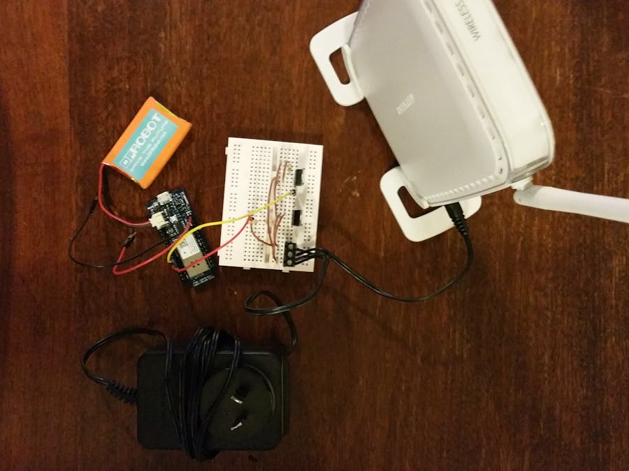
Our Wi-Fi connection at home tends to fail 2-3 times per week. The usual remedy is to turn the Wi-Fi router off and on again; which normally fixes it. When we are at home this is a pain, as we have to excavate the router from under a mass of twisted cables. When we are out, this is not possible; which is annoying as it prevents any remote desktoping to machines at our flat, and means any IoT devices/projects go belly up.
This project documents the design and build of an automated Wi-Fi power toggler which:
Detects a drop-out in the Wi-Fi internet connectionDisconnects power, waits and reconnects power to the Wi-Fi routerAutomatically fills out and submits a web log-in form (required with the internet connection we have in our apartment)Records these drop-outs, whether the power was out during the drop-out and whether the power-cycling restored internet access, in an online spreadsheet.
Build Instructions
The basic steps for the build are as follows:
1) Buy/find/salvage/scavenge the necessary hardware; other that the MKR1000 board it's mostly stuff you might have lying around.
2) Find your Wi-Fi router (it is probably under a twisted mess of cables under a desk somewhere)
3) Check the DC wall-wart for what voltage and current it puts out. Mine is rated to output 12V at 1A, but when I measured it with no load attached it was outputting about 16V.
4) Provided the voltage is below 35V, and the current below about 3A (I'd be surprised if they weren't); the hardware described in this project should work
5) Cut the DC-jack off-of the wall-wart, leaving a few centimeters of cable (to allow the jack to be plugged back into the Wi-Fi router later). This is a point of no return so you might want to put the other bits together first to check you've got it sorted. Also if there is no visible marking, use some tape to keep track of which of the two short wires from the DC-jack came from each of the two longer wires to the wall-wart.
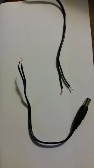
Cut the wires between the wall-wart and DC-jack (which plugs into router). Mark one of pair with tape.
6) Use a multi-meter to check the polarity of the wires coming from the wall-wart, and label them
7) Assemble the circuit as indicated on the schematic on the hardware page. PCB header terminals like these, are a good way of connecting the larger wires from the wall-wart and to the DC-jack onto the breadboard.
8) Customize the Arduino script (see below and the software page for details) to have the details of your Wi-Fi connection, etc. and then upload it to the MKR1000 board.
9) Turn on the wall-wart and enjoy never having to manually power-cycle your router ever again! And also have the satisfaction of a record being kept of the number of times this power-cycling has been necessary!
Customizing the Arduino Code
The hardware and software sections provide details of the hardware required, and the software which needs to be programmed onto the MKR1000 board. There are two additional steps that are required to get the full functionality.
The first is setting up a Google Form, and PushingBox account to allow the Arduino to report information about connection drop-outs and recoveries. For this project I have followed the excellent instructions here. There are quite a few steps, but if you follow them carefully you should get a PushingBox 'DeviceID' which you can paste into the Arduino sketch, and 'hey-presto' your Ardunio can upload stuff into a google docs spreadsheet.
The second is log-in details which may be required for your ISP (we have such a requirement in our apartment). To find these details, go to the landing page where you normally enter your login information. A screenshot of our log-in page is given below:
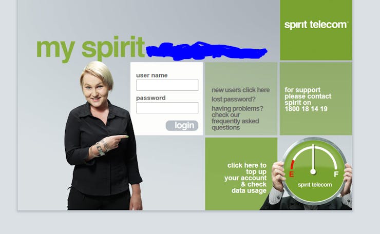
Web Login Page for our Internet
You then need to navigate to the source code of this page (most browsers will have an option to do so under the 'View' or 'Tools' menu). You are looking for the action which is taken when you submit the form (click the login button). The image below shows the source code for our landing page:
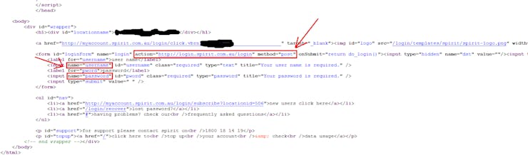
Source Code for Web Login Landing Page
Highlighted in the above source code are the action which is taken when the web login form is submitted (in this case an HTTP POST to login.spirit.com.au/login), and also the fields which are passed as part of this POST (namely 'username' and 'password').
Depending what you find you may need to modify the Arduino code a little beyond the section I've highlighted for editing, but if it's a similar set-up you simply need to replace the:
char serverLogin[] = "login.your.isp.name";
With an appropriate host name (in above example "login.spirit.com.au"), and the:
char loginSubPage[] = "/login";
With an appropriate URL extension (in the above example it is indeed just "/login"). As well as entering your landing page username and password.
A Word of Warning
If you include a 3.7V Li-Po battery in your version of this project you need to be careful about the heat dissipation in the linear regulator. I found that without a battery being charged the MKR1000 drew only about 20mA, so the dissipation in the linear regulator is about (16V in - 5V out) x 0.02A = 0.22W. The total thermal resistance between the junction and ambient for the TO-220 package from the data-sheet is about 55 degrees C / W; so this will cause a temperature rise of about 10 degrees C (just noticeable).
However, when the battery was connected and charging at the same time, the MKR1000 drew about 200mA, this will cause a temperature rise of around 100 degrees C, which on top of an ambient of 20 degrees C is only just within the maximum ratings for the device. If you are going to include a battery and allow it to be charged from the 5V regulated supply I would recommend fitting a decent heat-sink (or better still use a switch-mode-power supply).
Questions & Comments
It would be great to hear your thoughts on how I could improve the project, or make the description clearer. An obvious one would be moving it over to solder-board, and putting it in an enclosure; I do plan to do that (because this project is actually going to be put to use on my Wi-Fi router), but wasn't able to within time constraints of the MKR1000 competition.
Schematics
Wi-Fi Power Toggler Circuit Schematic
This shows the circuit schematic. On the left we have a screw terminal which the +16V and ground of the existing DC power supply (wall-wart) for the Wi-Fi Router connect. Our router put out 16Vdc, but the linear regulator will work with any DC power supply up to 35V.
The wall-wart provides power to the 7805 linear regulator which produces a regulated 5V output to power the MKR1000 board, via the (5V) pin (note the schematic shows the Arduino Nano, as now MKR1000 model was available).
A potential divider (made up of R1 and R2) drops the 5V to ~3.3V to be sensed by digital input (1), to check if mains power is present (MKR1000 will continue to run on battery in the event of a power outage; but the Wi-Fi connection will be dropped).
The MKR 1000 board is connected (via the 2-pin JST connector) to a 3.7V Li-Po battery.
Finally digital output (0) of the MKR 1000 drives the gate of an N-Channel power mosfet (via a 1k resistor, with a 100k pull-down resistor), which switches the ground connection to the Wi-Fi router, turning it on and off.
https://docs.google.com/viewerng/viewer?url=https://hacksterio.s3.amazonaws.com/uploads/pdf_file/file/137832/WiFi_Power_Toggler_Schematic_schem.pdf
Bread-Board Layout
This shows an approximate bread-board layout of the circuit. Note that the physical locations of the pins on the MKR1000 board are not correct, but rather the Pin IDs are correct (with the exception of A6, A7 where the battery connects; which in reality is via the 2-pin JST connector).
https://docs.google.com/viewerng/viewer?url=https://hacksterio.s3.amazonaws.com/uploads/pdf_file/file/137833/WiFi_Power_Toggler_Schematic_bb.pdf
The article was first published in hackster, March 30, 2016
cr: https://www.hackster.io/khalidaabdulla/wi-fi-power-toggler-0ed04a
author: Khalid Abdulla


