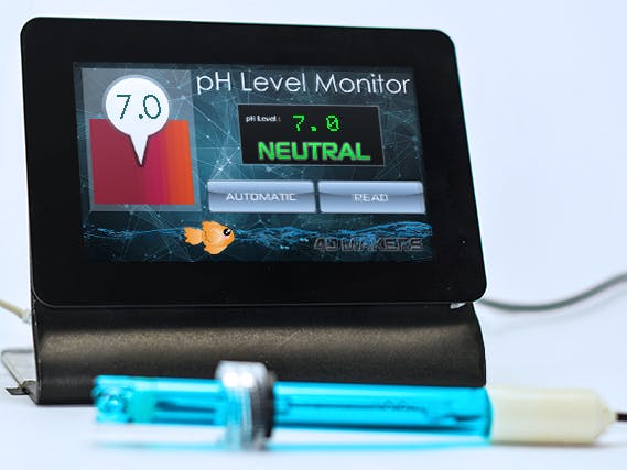
The pH Level Monitor project uses 4D Systems' gen4-uLCD-50DT to display the pH level of a certain substance.
Things used in this project
Hardware components
Story
The pH Level Monitor project uses 4D Systems' gen4-uLCD-50DT to display the pH level of a certain substance. It can also be used to monitor the acidity of your aquarium or pond.
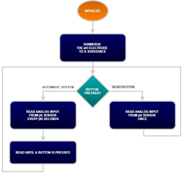
In this project, the pH level can be automatically or manually read when you press the buttons provided on the graphical user interface of the gen4 HMI Display. It is programmed using the Visi Environment of Workshop 4 IDE.
How it Works
Components
gen4-uLCD-50DCT-CLBgen4-PA and FFC CableAnalog pH Sensor Kit -pH Electrode -pH sensor circuit board -analog cablemicro USB CableConnecting Wires and 5V power Supply
Implementation
Step 1: Build
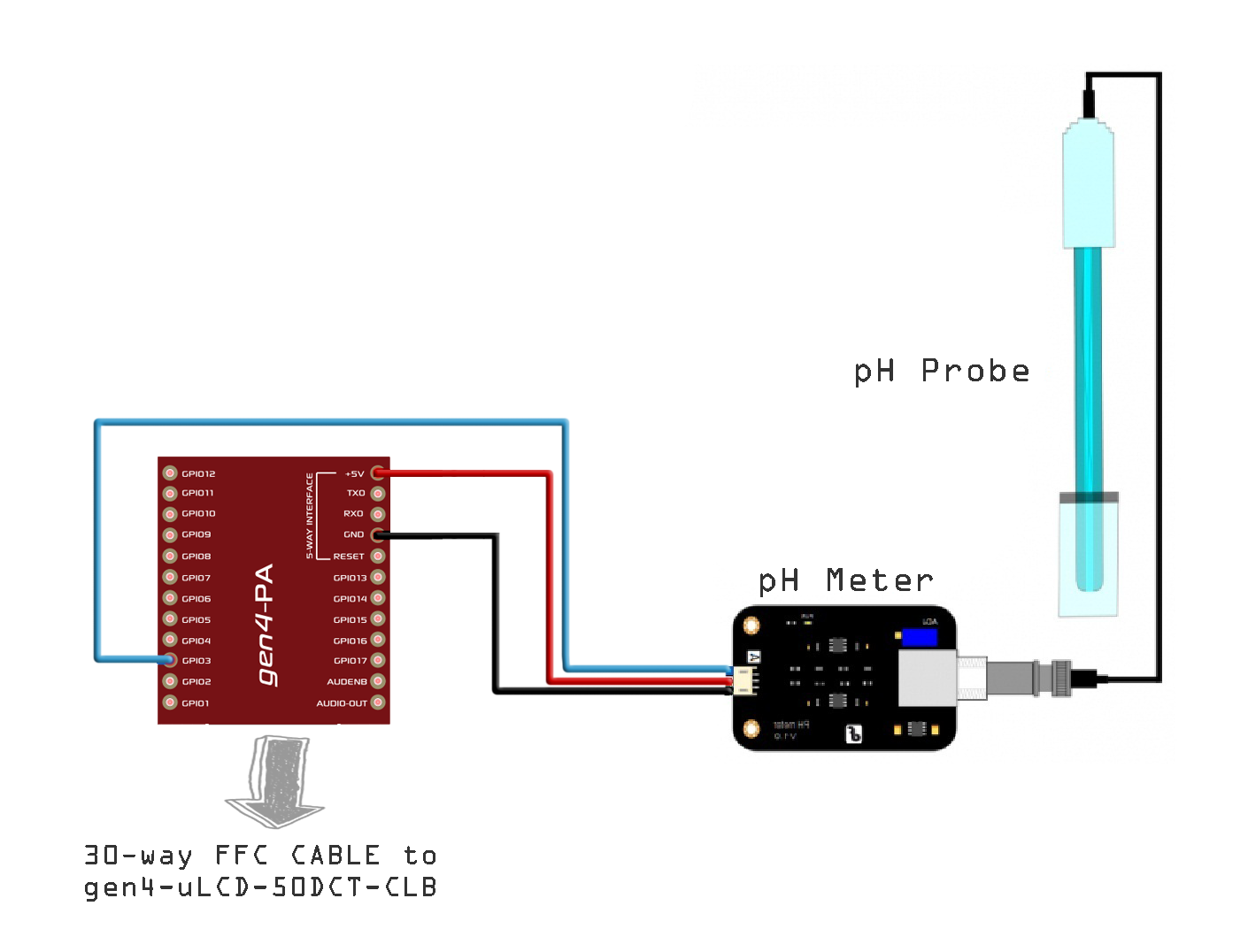
Build the circuit as shown in the diagram. Connect the gen4-PA to gen4-uLCD-50DCT-CLB or any gen4-HMI Display module with 480x800 px resolution.
Note: The graphics used in this project has 480x800px, but you can still costumize them into smaller displays.
Step 2: Program
Download the code here. Open the Visi project using Workshop 4. This project uses the Visi Environment. You can modify the properties of each widgets and buttons.
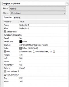
PA1 is set as analog input pin.

You can also check and modify some part of the code according to your preferences. Each sections and functions has comments for your reference
Displaying of pH Level and acidity indication:
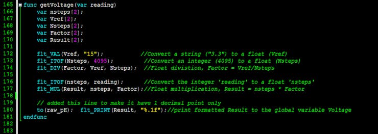
Analog voltage reading and conversionTouch Function of the pH Level Monitor
Step 3: Compile
Click on the “Compile” button.
Note: This step could be skipped. However, compiling is essential for debugging purposes.
Step 4: Comms Port
Connect the display to the PC. Make sure that you are connected to the right port. Red Button indicates that the device is not connected, Blue Button indicates that the device is connected to the right port.
Step 5: Compile and Upload
Go back to “Home” tab. This time, click on the “Comp’nLoad” button. Workshop 4 will prompt you to select a drive to copy the image files to a uSD Card. After selecting the correct drive, click OK.
Step6: Mount uSD Card
When the uSD card is not yet inserted, this message will appear on your gen4 Display: "Drive not mounted" After inserting your uSD card this GUI should appear on the gen4 Display:
Video
Schematics
Schematic Diagram