

Supplies
-Arduino Mega 2560
-Infineon PSoC 4100S Capsense Pioneer Kit
-LED Strip
-Resistor 10k ohm × 3
-Logic Level N-channel MOSFETs × 3
-Breadboard
-12V Power Supply
-9V Power Supply
-Jumper wires (generic)
For this project I also utilized a 3d printer, but if you don't have access to one there are viable workarounds.
The Idea of the Project
This is a light up, multicolored sign that activates when the user goes live on Twitch, can be controlled by Twitch chat via commands, and can be controlled in person with capacitive touch by utilizing the PSoC 4 Series Pioneer Kit (I'll be referring to the device I used as the PSoC 4100s for short).
I'm not too proud to admit that, like a moth, I am fond of shiny things. Unlike a moth, though, I am willing to spend a bunch of time and effort to make a project that is all about big shiny lights. Combine that with gaming, 3d printing, and fancy electronics you're supposed to poke and prod and we've got too many boxes checked for me to not get excited about the project. This expands on something I've wanted to make for awhile, which is the basic sign that indicates that the stream is live in person because it's not only fun, it is a useful way to give loved ones a heads up that there's a stream running to prevent embarrassing moments. I'm a big fan of giving myself cool ways to interact with gadgets, and giving fun interaction capabilities on Twitch is just fun, so the rest of the idea built itself out. With that, it's time to get into it!
Getting Going with Capacitive Touch (PSoC Setup)
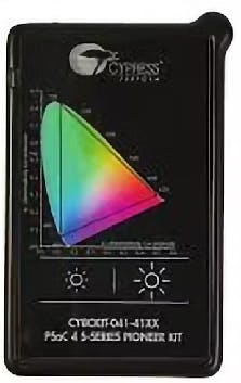
I started with getting the PSoC side of things up and running and utilized the PSoC Creator 4.4 software to get things up and running. The device comes with a very nice color selector and two buttons, which is absolutely perfect for what I'm looking to make here. It also comes with an example Color Gamut project, which serves as an excellent starting point for what we're trying to accomplish. Instead of just utilizing the base functionality, though, I altered how the buttons work to give myself a little bit more control.
The color pallet is fantastic, but it can be tricky to get a specific color, particularly because I'm a big dude and my finger press takes up half the pallet. As such, I setup one of the buttons to rotate through a selection of colors. This works by maintaining a color index, such that when the button is pressed, it increments the index until it has gone through each color then goes back to 1.
Similarly, I do still want to control the brightness, as well as be able to turn the LEDs on and off. As such, I used the other button to maintain a brightness index, which goes 0-5. This can be very conveniently utilized by multiplying the index value by 51 to get values 0-255, where 0 obviously turns off the sign.
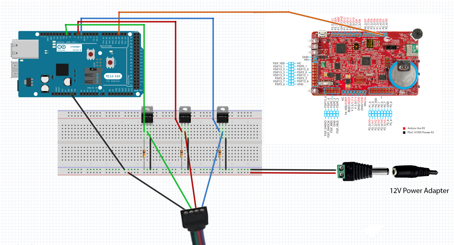
For the other aspects of the project that we'll get to momentarily, I utilized an Arduino setup to control the LEDs directly and listen for Twitch messages, so the ideal setup to integrate the PSoC device was to forward the input of the device to Arduino via serial messages. I added the TX pin for UART in the pin tab, and added the code for sending the serial messages via UART. This was setup to send the values for Red, Green, and Blue (RGB) coloration from the color gamut, the color index we setup, and the brightness index. Since we've setup the serial messages, we'll know exactly what to look for on the Arduino side. The TX pin is used to transfer information, and the RX pin receives it, so the setup is to use a jumper cable to connect the TX pin of the PSoC 4100s to the RX pin of the Arduino device.

With that, the capacitive touch aspect is functional, so it's time to make things bright and colorful!
Light It Up! (LED Setup)
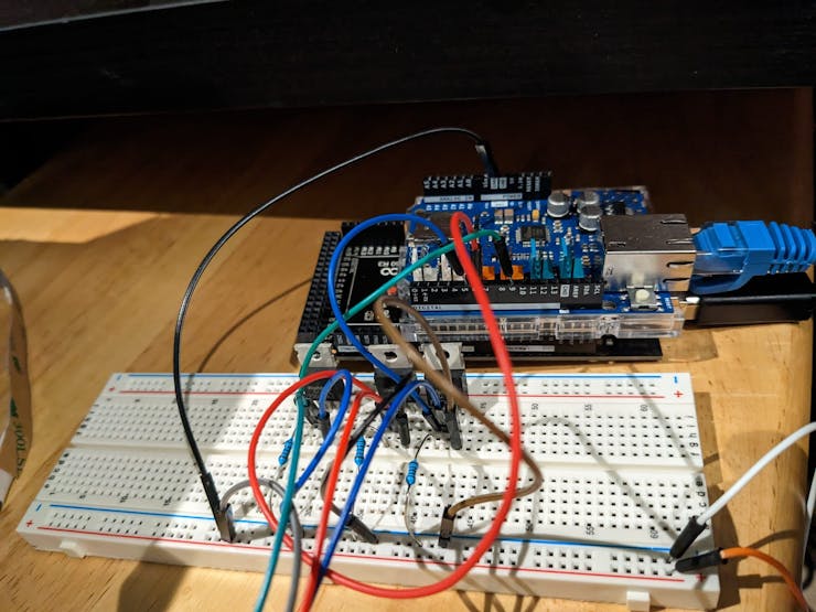
As I'll shoutout in the credit section, I referenced an article by "makeuseof" for setting up the LED strip. It's an ideal setup, because it can put LED strips to use that aren't specifically made for Arduino, which is what I happened to have available. In short, it uses Logic Level N-channel MOSFETs and 10k resistors to put together a simple breadboard setup that can safely connect the LED strip with the Arduino. This also requires a separate 12v power supply. The schematics are included in this project.
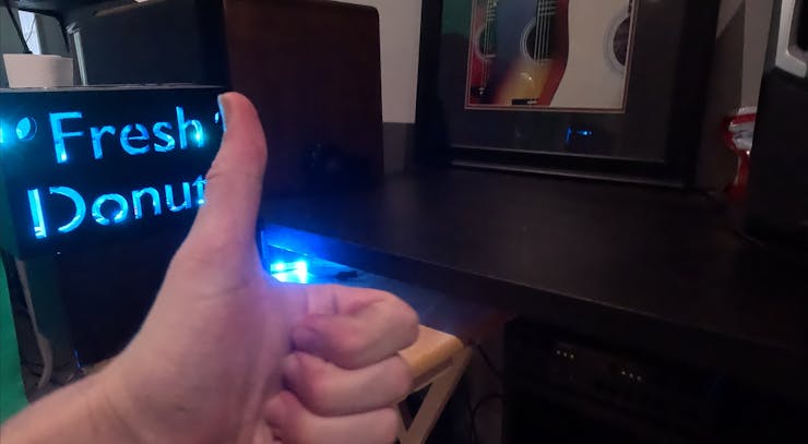
I waited until I was confident the project was fully complete before putting on the finishing touches, but it's a lot more fun to rock a custom light-up sign than it is a plain ol' LED strip so I went ahead and put the two together. The sign I used is a 3d printed sign I had designed. Thankfully, I had already printed it, which was more than a little convenient since my printer is all kinds of out of commission due to a tragic blob incident. While a 3d printed sign is cool, if you're following along and that's not your thing, there are plenty of other options for the same general setup using something like foam boards.
Adding the LED strip is just a matter of inserting it into the sign where it isn't directly in view. The LED strip I had was actually so old that I couldn't use its sticky side and had to tape it in place, but this was fine because I could just keep the tape out of sight. It's very satisfying to find purpose for unused components, and I was very happy with how it looked when I plugged it in.

The lights are all controlled via Arduino and the code for this is all included in the project, but the gist is that you give the Arduino values for red, blue, and green to light up the sign. If it's 255 for red, 0 for blue, and 0 for green, it's red at full brightness. However, you can also control the brightness with these numbers. Using the same example, if it's 50 for red, 0 for blue, and 0 for green, it's still red but dimmer. In the code, we retain the values, such that we can determine what color is being utilized such that if we increase the brightness we maintain the color that is currently being shown.
It's Mighty Morphin Microcontroller Time (Arduino Setup)
We have the lights, and now it's time for action. At this point, we can use Arduino to listen to serial messages from the PSoC device and update the sign accordingly. We process the messages coming in and use the RGB values to update the coloration. We can use the brightness index multiplied by 51 to create a value of 0-255 and use the logic I described in the previous section to update the LED's brightness. Finally, we'll shortly be delving into adding the Twitch commands, but the color index matches up with the color options I've associated with Twitch chat commands such that as we rotate through the index, it goes from one color to the next.
I normally tend to like seeing how much I can accomplish with cheap parts, but for this particular project I intend to use it long term and continue adding to it and tweaking it indefinitely. As such, I splurged a little bit on the components. I utilized an Arduino Mega, which has the advantage of extra serial ports and the capacity for longer programs. This turned out to not be necessary, but as we'll get to I thought the program was going to be much heftier. I also sometimes have issues with spotty Wi-Fi and want this to be consistent and reliable, so I used an Ethernet Shield. I, admittedly, also just wanted an excuse to try out an Ethernet Shield.
Fun fact, your ethernet cable has to actually work for your Ethernet connection to cooperate. Once the non-functional cable gets thrown into the trash and a good one is used, the setup for Ethernet is quite straightforward (as you'll see with the attached code)! That means that it's time to move onto giving Twitch the power to control the LEDs as well, because, after all, why shouldn't random people on the internet be able to control things in my house?
Here are the full schematics for the project:
I've Got the Power! Hey! (Twitch Setup)
The first key aspect to this is being able to listen to Twitch Chat messages with Arduino. To do so, you need a Twitch Chat Bot setup to provide a way to get access. You can go to the following URL and click "Register Your Application" to set this up: https://dev.twitch.tv/console.

You'll also want a valid oauth token, and can use something like https://twitchapps.com/tokengen/ to set that up.
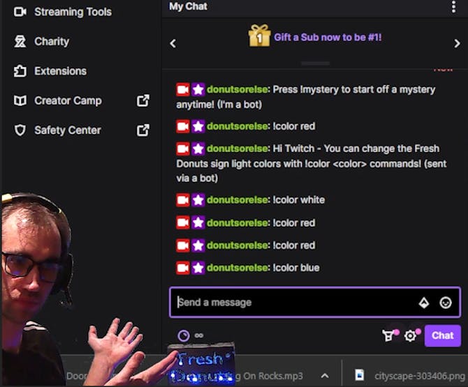
Once we're online with Ethernet, we start by connecting to Twitch. At this point, we can send a message in Twitch chat, which doubles as a way to let chatters know that they can use these commands as well as a way to visualize that the code is working. Afterward, we begin listening for messages in Twitch chat. Note: it seemed more straightforward to accomplish this by setting up a continuous loop, so I added in a call to listen for PSoC messages here as well, since it won't be running the main loop during this time.
The standard way to setup Twitch commands is to just use an "!" followed by the command. In this case, I set it up !color
Since the code is provided and I've already gone through the debugging process, it should just cooperate. However, if you have any issues with any of the client calls, I highly suggest using Postman. It's easy to use and provides very clear error messages, whereas sometimes it can be difficult to see what's going wrong with something like Arduino.
The... Easy Part?? (Stream Status Setup)
This still leaves adding the functionality to automatically turn the sign on and off based on the stream status. I was certain this would be one of the easiest parts of the project. After all, we were already making connections to Twitch and messing with the lights in more advanced ways. What could go wrong?
As it turns out, it was disinclined to acquiesce to my request. I received absolutely no response of any kind when trying to make the connection, despite confirming that everything was correct in Postman. My understanding at this point is that this is largely due to the fact that Arduino (or at least the libraries I tried) struggles with SSL and this was indeed an https call.
For science, I put together a quick program in Python and tried it out and it worked right off the bat, as Python does. Thankfully, it was about this time I had a very pleasant revelation. In preparation for this project I had been dabbling in other fun Twitch-related projects and I had very recently built a chat bot that hosts murder mysteries which runs in Python. This meant I had a Python program I fully intended to have running at all times as part of my intended full setup, and I could integrate just a little bit of extra logic into it to announce when the stream is live as well as when the stream ends. I'm aiming to all around have a nice and elegant project, and wanted to ensure this fit the bill. Once I realized that I would be able to delete all the Arduino code I added for this and add a simple extra segment to listen for chat messages and then turn the lights on and off, the functionality of which both exist in the project already, I realized it actually made the overall solution much cleaner. Since I want to provide everything needed for anyone following along to create a fully functional version of this project themselves, I created a simple, generified Python program that can be utilized and modified and have included it in the project. It can either be continuously run on a separate device like I intend to do, or you could utilize something like an esp32, which can run python code.
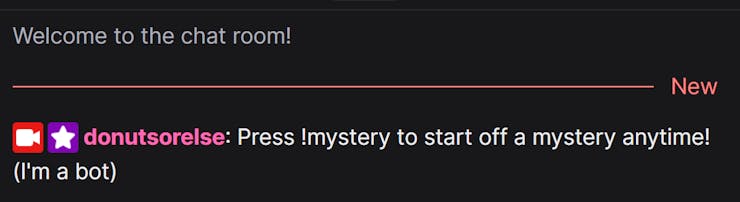
I modified the murder mystery chat bot to send a message in Twitch chat that says how to use the bot when the stream goes live, and a simple message that says that the stream has ended when it's over. This gives me simple messages to look for that are intuitive for the chat, and keep the chat clean of pointless messages like "the stream has started".
There is one concern you may be considering, which is that Twitch users can use the same messages to trick the Arduino. However, that just turns the lights on and off, which is the same functionality I'm giving them. It's almost like an Easter egg to reward clever chatters. But, if it ever did cause problems of some sort, I can always just modify the Arduino code slightly to look for who sent the message.
The Glam Up (Finalizing the Project)
I may or may not have had to google to make sure "glam up" was, in fact, a saying out there. Either way, it's time to make this thing pretty with some finishing touches and cable management.
This started with soldering. The PSoC device is the only one that needs to be accessible for use, since it's how I can control the sign. To do this neatly, I utilized a much longer cable that I could then conceal. Before beginning the process, though, I carved out a little notch in the case for the cable to fit through so that I could reattach the back of the case. Once that was done, I soldered the cable onto the same TX pin as before.
The nuances of the cable management would heavily depend on the setup, but I'll share what I did because I'm quite happy with the result. To be well positioned for the stream, the sign sits atop a box. I carved a hole in the box and fed the excess led strip through it and out the side. I then reconnected the LED strip and moved the Arduino and breadboard to where they sit underneath my desk out of sight. The cables run along the underside of my desk, such that all that is really visible is the sign and the PSoC device.
The finishing touch was attaching a back to the sign to make sure it shines nice and brightly. For this, I just used a thin piece of cardboard that I painted to match the rest of the sign. The difference once the back was added was pretty notable and really made the sign glow nicely.
With that, we're good to go. The sign turns on at the start of the Twitch stream, listens for Twitch commands and serial messages from the psoc device to change the colors and brightness of the sign, and turns off at the end of the stream. Hope you enjoyed the ride, and if you followed along and made this yourself I hope you enjoy your nifty new sign! Have a good one.
The Arduino Code - This controls the LED strip and listens for PSoC messages and Twitch commands
#include <SPI.h>
#include <Ethernet.h>

// Replace with the twitch bot's username
#define TWITCH_BOT_USERNAME "<your bot username>"

// Replace with the twitch bot's OAuth key
#define OAUTH_KEY "oauth:<your oauth token here>"

// Twitch IRC server and port
#define TWITCH_IRC_SERVER "irc.chat.twitch.tv"
#define TWITCH_IRC_PORT 6667

byte mac[] = {0xDE, 0xAD, 0xBE, 0xEF, 0xFE, 0xED};
// Ethernet client object
EthernetClient client;

#define RED_LED 6
#define BLUE_LED 5
#define GREEN_LED 9
int brightness = 255;

int greenValue = 0;
int redValue = 0;
int blueValue = 0;

int fadeSpeed = 10;
bool isLedOn = false;
boolean turnLedOn = false;
long previousCheck = 0L;
String channel = "<your channel here>";
String clientId = "<your client id here>";
#define TWITCH_CLIENT_ID "<your client id here>"
#define TWITCH_LOGIN "<your channel here>"

bool isStreamLive = false;
bool internetConnected = false;
int brightnessIndex, colorIndex, psocRed, psocGreen, psocBlue = -1;

unsigned long delayBetweenRequests = 60000; // Time between requests (1 minute)

void sendMessage(String message) {
  client.print("PRIVMSG #" + channel + " :" + message + "\r\n");
}

void turnOnOffLed(bool turnOn) {
  for (int i = 0; i < 256; i++) {
    analogWrite(GREEN_LED, brightness);
    analogWrite(RED_LED, brightness);
    analogWrite(BLUE_LED, brightness);
    if (turnOn)
      brightness++;
    else
      brightness--;
    delay(fadeSpeed);
  }
  isLedOn = turnOn;
}

void setLedColor(int red, int green, int blue) {
  //Update these values as well so we can use them for brightness settings
  greenValue = green;
  redValue = red;
  blueValue = blue;
  for (int i = 0; i < 256; i++) {
    analogWrite(GREEN_LED, green);
    analogWrite(RED_LED, red);
    analogWrite(BLUE_LED, blue);
    delay(fadeSpeed);
  }
  isLedOn = true;
}

void updateLEDStrip() {
  if (turnLedOn) {
    if (!isLedOn) {
      turnOnOffLed(true);
    }
    for (int i = 0; i < 256; i++) {
      analogWrite(GREEN_LED, greenValue);
      analogWrite(RED_LED, redValue);
      analogWrite(BLUE_LED, blueValue);
    }
  }
  else if (isLedOn)
    turnOnOffLed(false);

}

void changeBrightness(int brightness) {
  if (brightness >= 0 && brightness <= 255) {
    int newRedValue = redValue * brightness / 255;
    int newGreenValue = greenValue * brightness / 255;
    int newBlueValue = blueValue * brightness / 255;

    int totalColorValue = newRedValue + newGreenValue + newBlueValue;
    float redRatio = (float)newRedValue / (float)totalColorValue;
    float greenRatio = (float)newGreenValue / (float)totalColorValue;
    float blueRatio = (float)newBlueValue / (float)totalColorValue;

    newRedValue = redRatio * brightness;
    newGreenValue = greenRatio * brightness;
    newBlueValue = blueRatio * brightness;

    setLedColor(newRedValue, newGreenValue, newBlueValue);
  }
  else {
    // Handle error if the brightness value is not within the range of 0-255
    Serial.println("ERROR: Invalid brightness value. Brightness must be between 0 and 255.");
  }
}

//Function to change the color of the lights
void changeColor(String currentColor, int colorIndex) {
  Serial.println("New color: " + currentColor);
  if (currentColor == "red" || colorIndex == 1) {
    //Set the lights to red
    setLedColor(255, 0, 0);
  } else if (currentColor == "green" || colorIndex == 2) {
    //Set the lights to green
    setLedColor(0, 255, 0);
  } else if (currentColor == "blue" || colorIndex == 3) {
    //Set the lights to blue
    setLedColor(0, 0, 255);
  } else if (currentColor == "yellow" || colorIndex == 4) {
    //Set the lights to yellow
    setLedColor(255, 255, 0);
  } else if (currentColor == "purple" || colorIndex == 5) {
    //Set the lights to purple
    setLedColor(128, 0, 128);
  } else if (currentColor == "orange" || colorIndex == 6) {
    //Set the lights to orange
    setLedColor(255, 165, 0);
  } else if (currentColor == "white" || colorIndex == 7) {
    //Set the lights to white
    setLedColor(255, 255, 255);
  } else if (currentColor == "off") {
    //Turn the lights off
    turnOnOffLed(false);
  } else {
    Serial.println(currentColor + " is an invalid color");
  }
}

//Dont let twitch users do anything funky
String cleanString(String input) {
  input.trim(); // remove extra spaces from the beginning and end of the string
  input.replace(" ", ""); // remove all spaces in the string
  input.toLowerCase(); // set the string to all lowercase

  // remove any illegal characters
  for (int i = 0; i < input.length(); i++) {
    if (!isAlphaNumeric(input[i])) {
      input.remove(i, 1);
      i--;
    }
  }
  return input;
}

void updateLedFromTwitchChatMessage(String incomingMessage) {
  //Check for the "!color" command
  if (incomingMessage.startsWith("!color")) {
    //Extract the color value from the incoming message
    String color = cleanString(incomingMessage.substring(7));
    Serial.println("Color " + color);
    changeColor(color, -1);
  }
  //Check for the "brightness" command
  if (incomingMessage.startsWith("!brightness")) {
    //Extract the brightness value from the incoming message
    String cleanedString = cleanString(incomingMessage.substring(11));
    int newBrightness = cleanedString.toInt();
    //Check if the new brightness value is valid
    if ((newBrightness != 0 || cleanedString == "0") && newBrightness >= 0 && newBrightness <= 255) {

      //Change the brightness of the lights
      changeBrightness(newBrightness);
    } else {
      Serial.println(cleanedString + " is not a valid brightness");
    }
  }
}

void connectToTwitch() {
  // Connect to Twitch IRC server
  if (client.connect(TWITCH_IRC_SERVER, TWITCH_IRC_PORT)) {
    client.print("PASS " + String(OAUTH_KEY) + "\r\n");
    client.print("NICK " + String(TWITCH_BOT_USERNAME) + "\r\n");
    client.print("JOIN #"+channel"+\r\n");
  } else {
    // Connection failed
    Serial.println("ERROR: Connection to Twitch failed.");
    Serial.println("Error code: " + String(client.getWriteError()));
  }
}

void receiveTwitchMessages() {
  while (client.connected()) {
    if (client.available()) {
      String response = client.readStringUntil('\n');
      if (response == "PING :tmi.twitch.tv\r\n") {
        client.print("PONG :tmi.twitch.tv\r\n");
      } else {
        Serial.println(response);
        int startIndex = response.indexOf(":", 1);
        int endIndex = response.indexOf("\r\n");
        if (endIndex < 0)
          endIndex = response.length();

        if (startIndex != -1 && endIndex != -1) {
          String message = response.substring(startIndex + 1, endIndex);
          Serial.println("The message is " + message);
          if (message.startsWith("!")) {
            Serial.println("Sending message: " + message);
            updateLedFromTwitchChatMessage(message);
          } else if (message.indexOf("Press !mystery to start off a mystery anytime! (I'm a bot)") >= 0 && !isStreamLive) {
            isStreamLive = true;
            turnOnOffLed(isStreamLive);
          } else if (message.indexOf("The stream is now offline.") >= 0 && isStreamLive) {
            isStreamLive = false;
            turnOnOffLed(isStreamLive);
          }
        }
      }
    }
    //The loop is inaccessible, so just call for psoc messages here instead
    receivePsocMessages();    //Via serial
  }
  client.stop();
}

void receivePsocMessages() {
  // Check for incoming serial data from the PSOC

  if (Serial1.available() > 0) {
    int redHexValue, greenHexValue, blueHexValue, b, c;
    String incomingData = Serial1.readStringUntil('\n');

    Serial.print("incomingData ");
    Serial.println(incomingData);
    if (incomingData.startsWith("RGB:")) {

      // Extract the red, green, and blue values from the incoming data
      sscanf(incomingData.c_str(), "RGB:%02X%02X%02X", &redHexValue, &greenHexValue, &blueHexValue);

      Serial.print("RGB " + String(redHexValue) + " " + String(greenHexValue) + " " + String(blueHexValue));

      if (psocRed != redValue || psocGreen != greenValue || psocBlue != blueValue) {
        turnLedOn = true;
        psocRed, redValue = redHexValue;
        psocGreen, greenValue = greenHexValue;
        psocBlue, blueValue = blueHexValue;
        updateLEDStrip();
      }
    } else if (incomingData.startsWith("Brightness Index: ")) {

      // Extract the red, green, and blue values from the incoming data
      sscanf(incomingData.c_str(), "Brightness Index: %d", &b);
      Serial.print("Brightness Index: " + String(b));

      //Change the brightness of the lights
      if (b != brightnessIndex) {
        changeBrightness(51 * b); //goes from 0-255
        brightnessIndex = b;
      }
    } else if (incomingData.startsWith("Color Index: ")) {

      // Extract the red, green, and blue values from the incoming data
      sscanf(incomingData.c_str(), "Color Index: %d", &c);
      Serial.print("Color Index: " + String(c));

      if (c != colorIndex) {
        changeColor("", c);
        colorIndex = c;

      }
    }
  }
}
void setup() {
  //  pinMode(led, OUTPUT);
  pinMode(GREEN_LED, OUTPUT);
  pinMode(RED_LED, OUTPUT);
  pinMode(BLUE_LED, OUTPUT);

  turnOnOffLed(true);
  delay(5000);
  turnOnOffLed(false);
  Serial.begin(115200);
  Serial1.begin(115200);
  setupConnection();
  Serial.println("Setup done");
}
void setupConnection() {
  // start Ethernet and UDP
  if (Ethernet.begin(mac) == 0) {
    Serial.println("Failed to configure Ethernet using DHCP");
    // Check for Ethernet hardware present
    if (Ethernet.hardwareStatus() == EthernetNoHardware) {
      Serial.println("Ethernet shield was not found.  Sorry, can't run without hardware. :(");
    } else if (Ethernet.linkStatus() == LinkOFF) {
      Serial.println("Ethernet cable is not connected.");
    }
  } else {
    Serial.println("Internet is connected");
    internetConnected = true;
  }
  connectToTwitch();
  sendMessage("Hi Twitch - You can change the light colors with !color <color> commands! (sent via a bot)");

}

void loop() {
  if (millis() - previousCheck >= 120000L) { // check every 2 minutes
    previousCheck = millis();
    if (!internetConnected) {
      Serial.println("Attempting to setup connection");
      setupConnection();
    }
  }
  receiveTwitchMessages();  //Via IRC on ethernet
  receivePsocMessages();    //Via serial
}
The Python Code - this is a generified version of the code that you can utilize to check the stream status and send messages in Twitch Chat that the Arduino code can then listen for
import requests
import time
from twitchio.ext import commands
from twitchio.client import Client
from twitchio import Message

# Replace with your Twitch client ID and OAuth token
TWITCH_CLIENT_ID = 'your_client_id'
TWITCH_OAUTH_TOKEN = 'your_oauth_token'
TWITCH_LOGIN = 'your_login_name'
TWITCH_CHANNEL = 'twitch_channel_name'

# Keep track of the current stream status
stream_live = False

CHECK_INTERVAL = 60  # seconds


def is_stream_live():
    url = f'https://api.twitch.tv/helix/streams?user_login={TWITCH_LOGIN}'
    headers = {
        'Client-ID': TWITCH_CLIENT_ID,
        'Authorization': f'Bearer {TWITCH_OAUTH_TOKEN}'
    }
    response = requests.get(url, headers=headers)
    data = response.json()
    print(data)
    if data.get('data') and data['data'][0].get('type') == 'live':
        return True
    return False


def send_message(msg):
    bot = commands.Bot(
        irc_token='your_irc_token',
        client_id='your_client_id',
        nick='your_bot_name',
        prefix='!',
        initial_channels=[TWITCH_CHANNEL]
    )
    bot.run()
    bot._ws.send_privmsg(TWITCH_CHANNEL, msg)


def main():
    stream_live = False
    while True:
        live = is_stream_live()
        if live != stream_live:
            stream_live = live
            msg = 'The stream has started! Get in here for good times!' if live else 'The stream has ended. Hope you enjoyed!'
            send_message(msg)
            print(msg)
        time.sleep(CHECK_INTERVAL)


if __name__ == '__main__':
    main()
The PSoC Code - this is the updated main.c file for the Color Gamut example project, in which the buttons are modified and then data is sent to the Arduino device via UART
/******************************************************************************
* File Name: main.c
*
* Version: 1.00
*
* Description:  This code example demonstrates how to use CapSense trackpad
*               to input RGB color code for color mixing with PSoC 4 S-Series device.
*
* Related Document: CE214025 Trackpad with Color Gamut.pdf
*
* Hardware Dependency: See code example document CE214025 Trackpad with Color Gamut.pdf
*
******************************************************************************
* Copyright (2016), Cypress Semiconductor Corporation.
******************************************************************************
* This software, including source code, documentation and related materials
* ("Software") is owned by Cypress Semiconductor Corporation (Cypress) and is
* protected by and subject to worldwide patent protection (United States and
* foreign), United States copyright laws and international treaty provisions.
* Cypress hereby grants to licensee a personal, non-exclusive, non-transferable
* license to copy, use, modify, create derivative works of, and compile the
* Cypress source code and derivative works for the sole purpose of creating
* custom software in support of licensee product, such licensee product to be
* used only in conjunction with Cypress's integrated circuit as specified in the
* applicable agreement. Any reproduction, modification, translation, compilation,
* or representation of this Software except as specified above is prohibited
* without the express written permission of Cypress.
*
* Disclaimer: THIS SOFTWARE IS PROVIDED AS-IS, WITH NO WARRANTY OF ANY KIND,
* EXPRESS OR IMPLIED, INCLUDING, BUT NOT LIMITED TO, NONINFRINGEMENT, IMPLIED
* WARRANTIES OF MERCHANTABILITY AND FITNESS FOR A PARTICULAR PURPOSE.
* Cypress reserves the right to make changes to the Software without notice.
* Cypress does not assume any liability arising out of the application or use
* of Software or any product or circuit described in the Software. Cypress does
* not authorize its products for use as critical components in any products
* where a malfunction or failure may reasonably be expected to result in
* significant injury or death ("ACTIVE Risk Product"). By including Cypress's
* product in a ACTIVE Risk Product, the manufacturer of such system or application
* assumes all risk of such use and in doing so indemnifies Cypress against all
* liability. Use of this Software may be limited by and subject to the applicable
* Cypress software license agreement.
*****************************************************************************/
/*******************************************************************************
*   Included Headers
*******************************************************************************/
#include <project.h>

/* Include boolean function definition */
#include <stdbool.h>

/* Include color mixing API declarations */
#include "colormixing.h"

/* Include sprintf API definitions */
#include <stdio.h>

/*******************************************************************************
*   Macros and #define Constants
*******************************************************************************/

/*The UART variables*/
char string[100];   //Used to send the brightness data
#define SEND_INTERVAL       (2000u)


/* Intensity control button status */
#define BUTTON_ON                   (0x01u)
#define BUTTON_OFF                  (0x00u)

/* Multiplier value for color mixing to avoid floating point math */
#define POS_MULT_100                (100u)

/* Number of active sensors when palm is placed on trackpad */
#define ACTIVE_SENSORS_PALM          (4u)

/* Minimum and maximum intensity values. This value is divided by 10 and is multiplied
*  by MAX_COMPAREVALUE
*/
#define MAX_INTENSITY_LEVEL         (16u)

/* Default intensity value */
#define DEFAULT_LED_INTENSITY       (MAX_COMPAREVALUE/2)

/*LED wil be driven for the specified number of loops after no touch*/
#define MAX_LOOPS_TO_DRIVE_LED      (75u)

/*Index for brightness control array*/
#define MAX_INTENSITY_INDEX         (3u)
#define MIN_INTENSITY_INDEX         (0u)

/*LED brightness macros*/
#define LED_BRIGHTNESS_12_5         (2u)
#define LED_BRIGHTNESS_25_0         (4u)
#define LED_BRIGHTNESS_37_5         (6u)
#define LED_BRIGHTNESS_100_0        (16u)

/*Offset correction macros*/
#define MIN_X_COORDINATE            (15u)
#define MAX_X_COORDINATE            (75u)
#define MIN_Y_COORDINATE            (8u)
#define MAX_Y_COORDINATE            (77u)
#define Y_COORDINATE_OFFSET         (7u)
#define Y_COORDINATE_NEED_OFFSET    (29u)
#define MAX_X_COORDINATE_FOR_COLOR_MIXING   (64u)

/*******************************************************************************
*   Module Variable and Constant Declarations with Applicable Initializations
*******************************************************************************/

/* Finite state machine states for device operation */
typedef enum
{
    SENSOR_SCAN = 0x01u,    /* Sensor is scanned in this state */
    WAIT_FOR_SCAN_COMPLETE = 0x02u, /* CPU is put to sleep in this state */
    PROCESS_DATA = 0x03u,   /* Sensor data is processed */
} DEVICE_STATE;

const uint8 brightnessLevels[] = {LED_BRIGHTNESS_12_5,LED_BRIGHTNESS_25_0
                                    ,LED_BRIGHTNESS_37_5 ,LED_BRIGHTNESS_100_0};

uint8 brightnessIndex = MAX_INTENSITY_INDEX;

/*******************************************************************************
*  Function Declarations
*******************************************************************************/

/* Function prototype for CapSense parameter initialization */
void capSenseInit(void);

/* Function prototype to scan CapSense sensors */
void capSenseProcess(void);

/* Function prototype to initialize TCPWM components */
void prismInit(void);

/* Function that checks if trackpad or button sensors are ON */
bool anyWidgetActive(void);

/* Function that performs color mixing */
void colorMixingProcess(void);

/*******************************************************************************
*   Module Variable and Constant Declarations with Applicable Initializations
*******************************************************************************/

/* Contains current x, y coordinates of trackpad */
uint16 trackpadXPos = CapSense_SLIDER_POS_NONE;
uint16 trackpadYPos = CapSense_SLIDER_POS_NONE;

/* Variable to store color mixing error status */
uint8 colorMixingError;

/* Variable to store interrupt state */
uint32 interruptState = 0u;

/* Variable to store the current trackpad XY coordinates.
*  The XY coordinate is multiplied with 100 to avoid floating point math
*/
XY_COORDINATE currentXYCoordinate;

/* Variable to store last valid touch coordinates */
XY_COORDINATE lastValidXYCoordinate;

/* Variable to store RGB led dimming values */
uint16 rgbLEDDimmingValue[NUM_LEDS];

uint16 timeoutCounter;

/* Variable to store RGB LED coordinates on the color gamut
*  The coordinates are multiplied by 10000 to avoid floating point math
*/
LED_COORDINATE rgbLEDXYPosition[NUM_LEDS];

/* Variable to store On/Off condition of trackpad */
uint8 trackpadStatus = 0;

/* Variable to control the maximum intensity of RGB LED
*  Variable takes the following values 2, 4, 8 and 16
*  The resulting PWM compare value is multiplied with this value
*  and normalized to achieve duty cycle of 100%, 50%, 25% and 12.5%
*/
uint8 intensityCtrl = MAX_INTENSITY_LEVEL;

/* Variable to store the status of intensity control buttons */
uint8 button0CurrState = BUTTON_OFF;
uint8 button0PrevState = BUTTON_OFF;
uint8 button1CurrState = BUTTON_OFF;
uint8 button1PrevState = BUTTON_OFF;


/* Minimum and maximum brightness index */
#define MIN_BRIGHTNESS_INDEX 0
#define MAX_BRIGHTNESS_INDEX 5

/* Minimum and maximum color index */
#define MIN_COLOR_INDEX 1
#define MAX_COLOR_INDEX 7

/* Current color index */
uint8 colorIndex = MIN_COLOR_INDEX;


/******************************************************************************
* Function Name: main
*******************************************************************************
*
* Summary: This function implements the state machine for device operation.
*
* Parameters:
*  None.
*
* Return:
*  None.
*
* Theory:
*   main() performs following functions:
*  1: Initialize the CapSense, EZI2C and PWM Components
*  2: Scans trackpad, buttons and performs color mixing and brightness control using
*     RGB LED
*
* Side Effects: None
*
* Note:None
*
*******************************************************************************/

int main()
{
    /* Start the firmware state machine with sensor scan */
    DEVICE_STATE currentState = SENSOR_SCAN;

    /* Variable to hold active sensors count */
    uint16 sensorCount = 0u;

    /* Variable to check active sensor bits */
    uint16 mask = 0u;

    /* Temporary variable */
    uint16 tempVar = 0u;

    /* Enable interrupts. This is required for CapSense and I2C operation */
    CyGlobalIntEnable;

    /* Initialize I2C component for CapSense tuner */
    EZI2C_Start();

    /* Set up communication data buffer to CapSense data structure to
    * expose to I2C master at primary slave address request
    */
    EZI2C_EzI2CSetBuffer1(sizeof(CapSense_dsRam), sizeof(CapSense_dsRam),\
                         (uint8 *)&CapSense_dsRam);

    /* Start the CapSense component and autocalibrate IDAC values */
    capSenseInit();

    /* Initialize PWM components */
    prismInit();

    /* Load XY coordinates of RGB LED on color gamut into local variables */
    initializeLedCoordinates(rgbLEDXYPosition);

    SW_Tx_UART_1_Start();

    for(;;)
    {
        switch(currentState)
        {
            case SENSOR_SCAN:
			{
                /* Initiate new scan only if the CapSense hardware is idle */
                if(CapSense_NOT_BUSY == CapSense_IsBusy())
                {
                    /* Update CapSense parameters set via CapSense tuner */
                    CapSense_RunTuner();

                    /*Scan trackpad and buttons*/
                    CapSense_ScanAllWidgets();

                    /* Set the state machine to wait state until the scan is complete */
                    currentState = WAIT_FOR_SCAN_COMPLETE;
                }
            	break;
			}

			case WAIT_FOR_SCAN_COMPLETE:
			{
                /* Device is in CPU Sleep until CapSense scanning is complete or
                *  device is woken-up by either CapSense interrupt or I2C interrupt
                */
                /* Disable interrupts, so that ISR is not serviced while
                *  checking for CapSense scan status. Otherwise, interrupt might
                *  get serviced after checking for IsBusy condition and device
                *  might not wakeup since CapSense interrupt is already serviced
                */
                interruptState = CyEnterCriticalSection();

                /* Check if CapSense scanning is complete */
                if(CapSense_NOT_BUSY != CapSense_IsBusy())
                {
                    /* If CapSense scannning is in progress, put CPU to sleep
                    *  Device wakesup because of CapSense scan complete interrupt
                    */
                    CySysPmSleep();
                }
                /* If CapSense scanning is complete, process the CapSense data */
                else
                {
                    /* If current widget is trackpad or mode is slow scan mode, process the sensor data */
                    currentState = PROCESS_DATA;
                }
                /* Enable interrupts for servicing ISR */
                CyExitCriticalSection(interruptState);
            	break;
            }

			case PROCESS_DATA:
            {

                /* Set next state to Sensor Scan */
                currentState = SENSOR_SCAN;
                CapSense_ProcessAllWidgets();
                /* The below code resets trackpad baseline if a palm is detected on the trackpad */
                if(CapSense_IsWidgetActive(CapSense_TRACKPAD_WDGT_ID))
                {
                    /* Initialize mask variable */
                    mask = 1u;

                    /* Set active sensor count to zero */
                    sensorCount = 0u;

                    /* Loop through all the row and column sensors */
                    for(tempVar = CapSense_TRACKPAD_COL0_ID; tempVar <= CapSense_TRACKPAD_ROW6_ID; tempVar++)
                    {
                        /* Check each bit for active sensor condition */
                        if(CapSense_SNS_STATUS0_VALUE & mask)
                        {
                            /* Increment sensor count for each active sensor */
                           sensorCount++;
                        }
                        /* If all the column sensors are searched and active sensorCount is not greater than threshold
                        *  reset the sensorCount variable to detect active row sensors
                        */
                        if((tempVar == CapSense_TRACKPAD_COL6_ID) && (sensorCount <= ACTIVE_SENSORS_PALM))
                        {
                            sensorCount = 0u;
                        }

                        /* If active sensor count in either a row or column has exceed the threshold
                        *  reset all the trackpad sensor baselines
                        */
                        if(sensorCount > ACTIVE_SENSORS_PALM)
                        {
                            CapSense_InitializeWidgetBaseline(CapSense_TRACKPAD_WDGT_ID);
                            break;
                        }
                        /* Update the mask variable until all the bits are scanned for active status */
                        mask = mask << 1u;
                    }
                }
                /* Check if Left button is active */
                if(CapSense_IsWidgetActive(CapSense_INTENSITYUP_WDGT_ID))
                    button0CurrState = BUTTON_ON;
                else
                    button0CurrState = BUTTON_OFF;

                /* Check if Right button is active */
                if(CapSense_IsWidgetActive(CapSense_INTENSITYDOWN_WDGT_ID))
                    button1CurrState = BUTTON_ON;
                else
                    button1CurrState = BUTTON_OFF;

                /* Check for rising edge of Left button status  and toggle brightness value 0-5 */
                if((button0CurrState == BUTTON_ON) && (button0PrevState == BUTTON_OFF))
                {
                    if(brightnessIndex >= MAX_BRIGHTNESS_INDEX)
                    {
                        brightnessIndex = MIN_BRIGHTNESS_INDEX;
                    }
                    else
                    {
                        brightnessIndex++;
                    }
                }
                /* Check for rising edge of Right button status  and toggle color settings 1-7 */
                else if((button1CurrState == BUTTON_ON) && (button1PrevState == BUTTON_OFF))
                {
                    if(colorIndex >= MAX_COLOR_INDEX)
                    {
                        colorIndex = MIN_COLOR_INDEX;
                    }
                    else
                    {
                        colorIndex++;
                    }
                }

            /* Initialize previous button state to current button state */
            button0PrevState = button0CurrState;
            button1PrevState = button1CurrState;

            /* If trackpad or button sensor is not active, increment the LED timeout counter */
           if(!anyWidgetActive())
             {
                timeoutCounter++;

                /* Check if sensor is inactive for a duration greater than MAX_LOOPS_TO_DRIVE_LED */
                if(timeoutCounter >= MAX_LOOPS_TO_DRIVE_LED)
                {
                    /* Set LED pin drive mode to high-z to stop driving LEDs */
                    Red_LED_SetDriveMode(Red_LED_DM_ALG_HIZ);
                    Green_LED_SetDriveMode(Green_LED_DM_ALG_HIZ);
                    Blue_LED_SetDriveMode(Blue_LED_DM_ALG_HIZ);
                }
            }
            /* If either trackpad or button sensors are active, perform color mixing */
            else
            {
                /* Because sensor is active, reset the counter */
                timeoutCounter = 0;

                /* If widget is active, perform color mixing */
                colorMixingProcess();
            }
        	break;
        }

            default:
			{
            /*******************************************************************
             * Unknown state. Unexpected situation.
             ******************************************************************/
            	CYASSERT(0);
            	break;
			}
        }
    }
}

/******************************************************************************
* Function Name: capSenseInit
*******************************************************************************
*
* Summary: This API initializes CapSense block
*
* Parameters:
*  None.
*
* Return:
*  None.
*
* Theory:
*   capSenseInit() performs following functions:
*  1: Starts the CapSense block
*  2: Scan the trackpad widget and initialize the previous touch coordinate values
*
* Side Effects: None
*
* Note: None
*
*******************************************************************************/
void capSenseInit(void)
{
    /* Variable to store the XY coordinates */
    uint32 tempCoordinates;

    /* Initialize CapSense block */
    CapSense_Start();

    CapSense_InitializeWidgetBaseline(CapSense_INTENSITYUP_WDGT_ID);
    CapSense_InitializeWidgetBaseline(CapSense_INTENSITYDOWN_WDGT_ID);

    /* Scan the trackpad widget and initialize the previous touch coordinate values*/
    trackpadStatus =  CapSense_IsWidgetActive(CapSense_TRACKPAD_WDGT_ID);

    /* Get XY Coordinates */
    tempCoordinates = CapSense_GetXYCoordinates(CapSense_TRACKPAD_WDGT_ID);

    /* Load XY position to variable. Note: the XY position is interchanged as the
    *  columns and rows in the PCB layout is inverse of X, Y coordinate of color gamut
    */
    trackpadYPos = LO16(tempCoordinates);
    trackpadXPos = HI16 (tempCoordinates);

    /* Initialize last valid coordinates so that RGB LED glows
    *  when button is touched before trackpad after device power-up or reset.
    */
    lastValidXYCoordinate.currentX = RED_BASE_COLOR_X;
    lastValidXYCoordinate.currentY = RED_BASE_COLOR_Y;

    /* Set default led intensity value */
    currentXYCoordinate.ledIntensity = DEFAULT_LED_INTENSITY;
}

/******************************************************************************
* Function Name: prismInit
*******************************************************************************
*
* Summary: This API initializes PWM components
*
* Parameters:
*  None.
*
* Return:
*  None.
*
* Theory:
*  prismInit() performs following functions:
*  1: Starts the TCPWM block
*  2: Initializes the TCPWM compare value to minimum value
*
* Side Effects: None
*
* Note: None
*
*******************************************************************************/
void prismInit(void)
{
    /* Start TCPWM Blocks */
    PrISM_Red_Start();
    PrISM_Green_Start();
    PrISM_Blue_Start();

    /* Set TCPWM compare value to zero initially */
    PrISM_Red_WriteCompare(MIN_COMPAREVALUE);
    PrISM_Green_WriteCompare(MIN_COMPAREVALUE);
    PrISM_Blue_WriteCompare(MIN_COMPAREVALUE);

}
/*******************************************************************************
* Function Name: anyWidgetActive
********************************************************************************
*
* Summary:
*  This API checks if any widget is active
*
* Parameters:
*  None.
*
* Theory: This API checks if any of the IntensityUp, IntensityDown or trackpad sensors
*         are active and returns true if any one of them is active.
*
* Side Effects: None
*
* Note: None
*
*******************************************************************************/

bool anyWidgetActive(void)
{
    /* Check if either trackpad or any of the two button sensors are active */
    if(CapSense_IsWidgetActive(CapSense_TRACKPAD_WDGT_ID) || \
       CapSense_IsWidgetActive(CapSense_INTENSITYUP_WDGT_ID) || \
       CapSense_IsWidgetActive(CapSense_INTENSITYDOWN_WDGT_ID))
    {
        return TRUE;
    }
    else
    {
        return FALSE;
    }
}

/*******************************************************************************
* Function Name: colorMixingProcess
********************************************************************************
*
* Summary:
*  This API checks if any widget is active and computes the TCPWM compare value
*
* Parameters:
*  None.
*
* Theory: This API checks if any of the IntensityUp, IntensityDown or trackpad sensors
*         are active. Based on the status, the color mixing algorithm is executed to
*         compute the compare
*
* Side Effects: None
*
* Note: None
*
*******************************************************************************/
void colorMixingProcess(void)
{
    /* Temporary variable */
    uint32 tempVar;

    /* Variable to store XY coordinates of trackpad */
    uint32 tempCoordinates;

    /* Obtain the maximum compare value depending on the intensity level set by user */
    tempVar = (uint32) (intensityCtrl * MAX_COMPAREVALUE);
    tempVar /= MAX_INTENSITY_LEVEL;
    currentXYCoordinate.ledIntensity = (uint16)tempVar;
    lastValidXYCoordinate.ledIntensity = currentXYCoordinate.ledIntensity;

    /* Check if trackpad is active */
    trackpadStatus =  CapSense_IsWidgetActive(CapSense_TRACKPAD_WDGT_ID);

    /* Get trackpad XY coordinates */
    tempCoordinates = CapSense_GetXYCoordinates(CapSense_TRACKPAD_WDGT_ID);

    /* XY position values and store in local variable
    *  Note: The XY position is interchanged because the rows and columns are
    *  interchanged in the kit
    */
    trackpadYPos = LO16(tempCoordinates);
    trackpadXPos = HI16(tempCoordinates);

    /* If trackpad is active, load the XY position for computing dimming values */
    if(trackpadStatus)
    {
        /* Normalization is done because row0 to row6 and column0 to column 6
        *  are inverted in the layout
        */
        trackpadXPos = CapSense_TRACKPAD_Y_RESOLUTION - trackpadXPos;
        trackpadYPos = CapSense_TRACKPAD_X_RESOLUTION - trackpadYPos;

        /*Offset correction to get smooth response near color gamut edges*/
        if(trackpadXPos <= MIN_X_COORDINATE)
        {
            trackpadXPos = MIN_X_COORDINATE;
        }
        else if (trackpadXPos >= MAX_X_COORDINATE_FOR_COLOR_MIXING && trackpadXPos <= MAX_X_COORDINATE)
        {
            trackpadXPos = MAX_X_COORDINATE_FOR_COLOR_MIXING;
        }

        if(trackpadYPos <= MIN_Y_COORDINATE)
        {
            trackpadYPos = MIN_Y_COORDINATE;
        }
        else if (trackpadYPos <= Y_COORDINATE_NEED_OFFSET)
        {
            trackpadYPos = trackpadYPos + Y_COORDINATE_OFFSET;
        }
        else if(trackpadYPos >= MAX_Y_COORDINATE)
        {
            trackpadYPos = MAX_Y_COORDINATE;
        }

    }
    else
    {
        trackpadXPos = 0u;
        trackpadYPos = 0u;
    }

    /* Multiply the coordinate value by 100 to avoid floating point math */
    currentXYCoordinate.currentX = (int16)(trackpadXPos * POS_MULT_100);
    currentXYCoordinate.currentY = (int16)(trackpadYPos * POS_MULT_100);

    /* If finger is on trackpad, use current touch coordinates to compute dimming values */
    if(trackpadStatus)
    {
        /* Compute RGB LED dimming values for a given XY coordinate */
        colorMixingError = rgbColorMix(currentXYCoordinate, rgbLEDXYPosition, rgbLEDDimmingValue);

        /* If color mixing was successful, save the current coordinates */
        if(colorMixingError != INVALID_COLOR)
        {
            lastValidXYCoordinate.currentX = currentXYCoordinate.currentX;
            lastValidXYCoordinate.currentY = currentXYCoordinate.currentY;
        }
    }
    /* If IntensityUp or IntensityDown button is pressed, compute dimming value using previous saved touch coordinates */
    else
    {
        colorMixingError = rgbColorMix(lastValidXYCoordinate, rgbLEDXYPosition, rgbLEDDimmingValue);
    }

    /* Update the LED dimming value only when color mixing process is successful */
    if(colorMixingError != INVALID_COLOR)
    {
        /* Set LED pin drive mode to strong to save power */
        Red_LED_SetDriveMode(Red_LED_DM_STRONG);
        Green_LED_SetDriveMode(Green_LED_DM_STRONG);
        Blue_LED_SetDriveMode(Blue_LED_DM_STRONG);

        /* Load the computed dimming value to the PrISM component */
        PrISM_Red_WriteCompare(rgbLEDDimmingValue[LED_RED]);
        PrISM_Green_WriteCompare(rgbLEDDimmingValue[LED_GREEN]);
        PrISM_Blue_WriteCompare(rgbLEDDimmingValue[LED_BLUE]);


        /* Transmit different data types through the UART */
        SW_Tx_UART_1_PutString("RGB:");
        SW_Tx_UART_1_PutHexByte(rgbLEDDimmingValue[LED_RED]);
        SW_Tx_UART_1_PutHexByte(rgbLEDDimmingValue[LED_GREEN]);
        SW_Tx_UART_1_PutHexByte(rgbLEDDimmingValue[LED_BLUE]);
        SW_Tx_UART_1_PutCRLF();

        SW_Tx_UART_1_PutString("Brightness Index: ");
        SW_Tx_UART_1_PutHexInt(brightnessIndex);
        SW_Tx_UART_1_PutCRLF();

        SW_Tx_UART_1_PutString("Color Index: ");
        SW_Tx_UART_1_PutHexInt(colorIndex);
        SW_Tx_UART_1_PutCRLF();

        CyDelay(SEND_INTERVAL);
        SW_Tx_UART_1_PutCRLF();
    }
}


/* [] END OF FILE */


