
Intelligent Feedback System for Assistive Walking Technology is a device that provides real-time feedback to patients with lower limb disabilities to improve their walking time and overall walking pattern. By using a combination of sensors and a Neurosensory Buzz, our device provides users with sensory feedback that helps them better understand their gait and improve their walking. It can be used in conjunction with the open-source Exosuit project to provide better rehabilitation for people. Our project is open-source, meaning it can be easily replicated and adapted by others. With our device, we hope to make a positive impact on the lives of people with lower limb disabilities worldwide.

Overview
We provide detailed and step-by-step instructions on how to connect and program these components to build the device. We also include clear images, diagrams, and code snippets to help readers follow along.
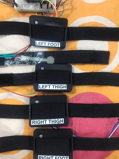
The motors will be connected to the patient's body and will make the user move. The sensory feedback will be provided by the gyroscope and accelerometer connected to the patient's body. There will be an array of force effective sensors connected to the patient's foot. The sensor array gives feedback to the Neurosensory Buzz so that the user will get a sense of each step and will improve the walking time and overall walking pattern.
The device is used along with the open-source Exosuit project to provide better rehabilitation for people.
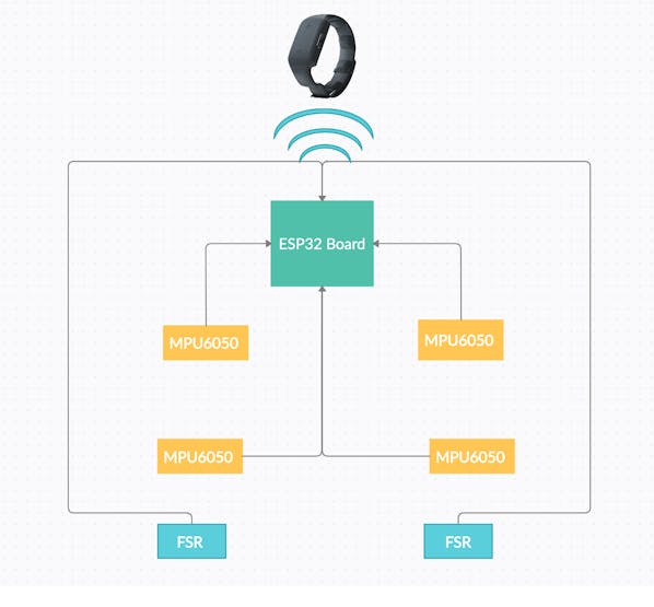
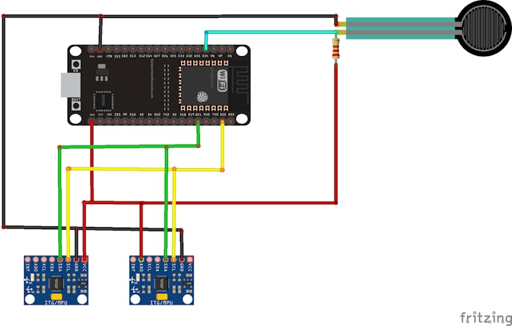
Block Diagram
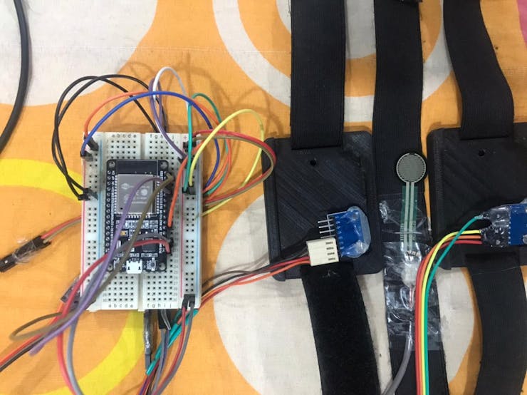
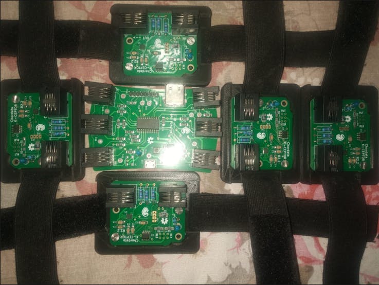
The MPU 6050 modules and FSR are connected to the ESP32 board and the neosensory Buzz will receive BLE signals from ESP32.
Step 1 : Connecting ESP32 with Neosensory buzz
I have used the Neosensory SDK for esp32. The complete detail how to install it can be found in the following link
I have used the Connect and Vibrate code

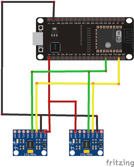
Step 2 : Connecting multiple MPU6050 with ESP32 (I2C)
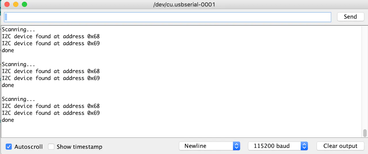
I2C Scanning
Use I2C scanning code given below to find the addresses of the sensor. Follow the Circuit diagram to make the connection diagram.
#include <Wire.h>

void setup() {
  Wire.begin();
  Serial.begin(115200);
  Serial.println("\nI2C Scanner");
}

void loop() {
  byte error, address;
  int nDevices;
  Serial.println("Scanning...");
  nDevices = 0;
  for(address = 1; address < 127; address++ ) {
    Wire.beginTransmission(address);
    error = Wire.endTransmission();
    if (error == 0) {
      Serial.print("I2C device found at address 0x");
      if (address<16) {
        Serial.print("0");
      }
      Serial.println(address,HEX);
      nDevices++;
    }
    else if (error==4) {
      Serial.print("Unknow error at address 0x");
      if (address<16) {
        Serial.print("0");
      }
      Serial.println(address,HEX);
    }
  }
  if (nDevices == 0) {
    Serial.println("No I2C devices found\n");
  }
  else {
    Serial.println("done\n");
  }
  delay(5000);
}
Multiple sensor connections
#include <Wire.h>
const int MPU2 = 0x69, MPU1=0x68;
long accelX, accelY, accelZ;
float gForceX, gForceY, gForceZ, gyroX, gyroY, gyroZ,rotX, rotY, rotZ;
long accelX2, accelY2, accelZ2;
float gForceX2, gForceY2, gForceZ2;
void setup(){
Wire.begin();
Wire.beginTransmission(MPU1);
Wire.write(0x6B);
Wire.write(0b00000000);
Wire.endTransmission();
Wire.beginTransmission(MPU1);
Wire.write(0x1B);
Wire.write(0x00000000);
Wire.endTransmission();
Wire.beginTransmission(MPU1);
Wire.write(0x1C);
Wire.write(0b00000000);
Wire.endTransmission();
Wire.begin();
Wire.beginTransmission(MPU2);
Wire.write(0x6B);
Wire.write(0b00000000);
Wire.endTransmission();
Wire.beginTransmission(MPU2);
Wire.write(0x1B);
Wire.write(0x00000000);
Wire.endTransmission();
Wire.beginTransmission(MPU2);
Wire.write(0x1C);
Wire.write(0b00000000);
Wire.endTransmission();
Serial.begin(115200);
}
void loop(){
GetMpuValue(MPU1);
Serial.print("\t ||| \t");
GetMpuValue(MPU2);
Serial.println("");
}
void GetMpuValue(const int MPU){
Wire.beginTransmission(MPU);
Wire.write(0x3B);
Wire.endTransmission();
Wire.requestFrom(MPU,6);
while(Wire.available() < 6);
accelX = Wire.read()<<8|Wire.read();
accelY = Wire.read()<<8|Wire.read();
accelZ = Wire.read()<<8|Wire.read();
Wire.beginTransmission(MPU);
Wire.write(0x43);
Wire.endTransmission();
Wire.requestFrom(MPU,6);
while(Wire.available() < 6);
gyroX = Wire.read()<<8|Wire.read();
gyroY = Wire.read()<<8|Wire.read();
gyroZ = Wire.read()<<8|Wire.read();
gForceX = accelX / 16384.0;
gForceY = accelY / 16384.0;
gForceZ = accelZ / 16384.0;
rotX = gyroX / 131.0;
rotY = gyroY / 131.0;
rotZ = gyroZ / 131.0;
Serial.print("gyro\t");
Serial.print(rotX);
Serial.print("\t");
Serial.print(rotY);
Serial.print("\t");
Serial.print(rotZ);
Serial.print("\tAcc\t");
Serial.print(gForceX);
Serial.print("\t");
Serial.print(gForceY);
Serial.print("\t");
Serial.print(gForceZ);
delay(100);
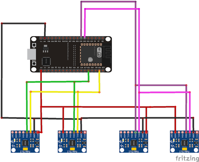
}Connection of 4 MPU6050 sensors with ESP32
#include <Wire.h>
#define SDA_2 33
#define SCL_2 32

const int MPU1 = 0x69, MPU2=0x68 , MPU3 = 0x69, MPU4=0x68;

long accelX, accelY, accelZ;
float gForceX, gForceY, gForceZ, gyroX, gyroY, gyroZ,rotX, rotY, rotZ;
long accelX2, accelY2, accelZ2;
float gForceX2, gForceY2, gForceZ2;

void setup(){
  Wire.begin();
  Wire.beginTransmission(MPU1);
  Wire.write(0x6B);
  Wire.write(0b00000000);
  Wire.endTransmission();
  Wire.beginTransmission(MPU1);
  Wire.write(0x1B);
  Wire.write(0x00000000);
  Wire.endTransmission();
  Wire.beginTransmission(MPU1);
  Wire.write(0x1C);
  Wire.write(0b00000000);
  Wire.endTransmission();

  Wire.beginTransmission(MPU2);
  Wire.write(0x6B);
  Wire.write(0b00000000);
  Wire.endTransmission();
  Wire.beginTransmission(MPU2);
  Wire.write(0x1B);
  Wire.write(0x00000000);
  Wire.endTransmission();
  Wire.beginTransmission(MPU2);
  Wire.write(0x1C);
  Wire.write(0b00000000);
  Wire.endTransmission();


  Wire1.begin(SDA_2, SCL_2);
  Wire1.beginTransmission(MPU3);
  Wire1.write(0x6B);
  Wire1.write(0b00000000);
  Wire1.endTransmission();
  Wire1.beginTransmission(MPU3);
  Wire1.write(0x1B);
  Wire1.write(0x00000000);
  Wire1.endTransmission();
  Wire1.beginTransmission(MPU3);
  Wire1.write(0x1C);
  Wire1.write(0b00000000);
  Wire1.endTransmission();

  Wire1.begin(SDA_2, SCL_2);
  Wire1.beginTransmission(MPU4);
  Wire1.write(0x6B);
  Wire1.write(0b00000000);
  Wire1.endTransmission();
  Wire1.beginTransmission(MPU4);
  Wire1.write(0x1B);
  Wire1.write(0x00000000);
  Wire1.endTransmission();
  Wire1.beginTransmission(MPU4);
  Wire1.write(0x1C);
  Wire1.write(0b00000000);
  Wire1.endTransmission();

  Serial.begin(115200);

}

void loop(){
  GetMpuValue1(MPU1);
  Serial.print("\t ||| \t");

  GetMpuValue1(MPU2);
  Serial.println("");

 GetMpuValue2(MPU3);
  Serial.print("\t ||| \t");

  GetMpuValue2(MPU4);
  Serial.println("");

}

void GetMpuValue1(const int MPU){
  Wire.beginTransmission(MPU);
  Wire.write(0x3B);
  Wire.endTransmission();
  Wire.requestFrom(MPU,6);
  while(Wire.available() < 6);
  accelX = Wire.read()<<8|Wire.read();
  accelY = Wire.read()<<8|Wire.read();
  accelZ = Wire.read()<<8|Wire.read();

  Wire.beginTransmission(MPU);
  Wire.write(0x43);
  Wire.endTransmission();
  Wire.requestFrom(MPU,6);
  while(Wire.available() < 6);
  gyroX = Wire.read()<<8|Wire.read();
  gyroY = Wire.read()<<8|Wire.read();
  gyroZ = Wire.read()<<8|Wire.read();


  gForceX = accelX / 16384.0;
  gForceY = accelY / 16384.0;
  gForceZ = accelZ / 16384.0;
  rotX = gyroX / 131.0;
  rotY = gyroY / 131.0;
  rotZ = gyroZ / 131.0;
  Serial.print("gyro\t");
  Serial.print(rotX);
  Serial.print("\t");
  Serial.print(rotY);
  Serial.print("\t");
  Serial.print(rotZ);
  Serial.print("\tAcc\t");
  Serial.print(gForceX);
  Serial.print("\t");
  Serial.print(gForceY);
  Serial.print("\t");
  Serial.print(gForceZ);
  delay(100);

}

void GetMpuValue2(const int MPU){
  Wire1.beginTransmission(MPU);
  Wire1.write(0x3B);
  Wire1.endTransmission();
  Wire1.requestFrom(MPU,6);
  while(Wire1.available() < 6);
  accelX = Wire.read()<<8|Wire.read();
  accelY = Wire.read()<<8|Wire.read();
  accelZ = Wire.read()<<8|Wire.read();

  Wire1.beginTransmission(MPU);
  Wire1.write(0x43);
  Wire1.endTransmission();
  Wire1.requestFrom(MPU,6);
  while(Wire1.available() < 6);
  gyroX = Wire.read()<<8|Wire.read();
  gyroY = Wire.read()<<8|Wire.read();
  gyroZ = Wire.read()<<8|Wire.read();


  gForceX = accelX / 16384.0;
  gForceY = accelY / 16384.0;
  gForceZ = accelZ / 16384.0;
  rotX = gyroX / 131.0;
  rotY = gyroY / 131.0;
  rotZ = gyroZ / 131.0;
  Serial.print("gyro\t");
  Serial.print(rotX);
  Serial.print("\t");
  Serial.print(rotY);
  Serial.print("\t");
  Serial.print(rotZ);
  Serial.print("\tAcc\t");
  Serial.print(gForceX);
  Serial.print("\t");
  Serial.print(gForceY);
  Serial.print("\t");
  Serial.print(gForceZ);
  delay(100);

}
Step 3 :Data forwarding sensor data to the edge Impulse
Plan A was to connect 6 sensors and do data forwarding to edge impulse but it was hard for me to train with 6 sensors and each MPU6050 with 6 axis.
Plan B is to connect one leg at a time and train and test the sensors one leg will have 2 MP6050 sensors and one FSR.
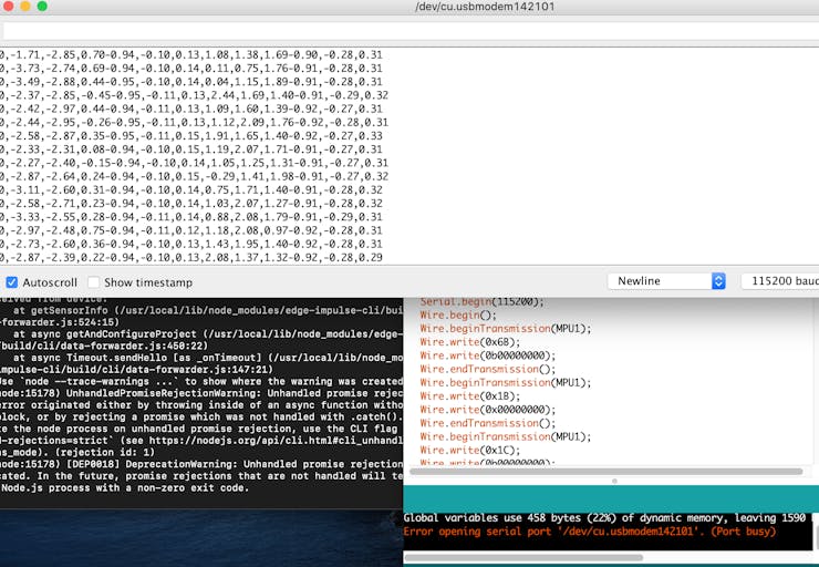
To use the data forwarder, load an application on your development board, and run:
$ edge-impulse-data-forwarder
Clearing configuration To clear the configuration, run:
$ edge-impulse-data-forwarder --clean
Overriding the frequency
$ edge-impulse-data-forwarder --frequency 100
It is simple the device should send data on baud rate 115, 200 with one line per reading, and individual sensor data should be split with either a ', 'or a TAB. For example, this is data from a 3-axis accelerometer:
-0.12,-6.20,7.90
-0.13,-6.19,7.91
-0.14,-6.20,7.92
-0.13,-6.20,7.90
-0.14,-6.20,7.90
In order to make it wireless, I transferred the sensor data to a Wio terminal board through BLE.
- Follow this tutorial to use BLE with Wio terminal - Now upload the code given below to communicate with the Wio terminal. - The BLE data received would be shown in the Serial monitor which we can use for data forwarding for edge impulse.#include "rpcBLEDevice.h"#include <BLE2902.h>#include <TFT_eSPI.h> // Hardware-specific library#include <SPI.h>TFT_eSPI tft = TFT_eSPI(); // Invoke custom libraryTFT_eSprite spr = TFT_eSprite(&tft); // Sprite BLEServer *pServer = NULL;BLECharacteristic * pTxCharacteristic;bool deviceConnected = false;bool oldDeviceConnected = false;String Value11; #define SERVICE_UUID "6E400001-B5A3-F393-E0A9-E50E24DCCA9E" // UART service UUID#define CHARACTERISTIC_UUID_RX "6E400002-B5A3-F393-E0A9-E50E24DCCA9E"#define CHARACTERISTIC_UUID_TX "6E400003-B5A3-F393-E0A9-E50E24DCCA9E" class MyServerCallbacks: public BLEServerCallbacks { void onConnect(BLEServer* pServer) { deviceConnected = true; spr.fillSprite(TFT_BLACK); spr.createSprite(240, 100); spr.setTextColor(TFT_WHITE, TFT_BLACK); spr.setFreeFont(&FreeSansBoldOblique12pt7b); spr.drawString("Message: ", 20, 70); spr.setTextColor(TFT_GREEN, TFT_BLACK); spr.drawString("status: connected",10 ,5); spr.pushSprite(0, 0); }; void onDisconnect(BLEServer* pServer) { deviceConnected = false; Serial.print("123123"); spr.fillSprite(TFT_BLACK); spr.createSprite(240, 100); spr.setTextColor(TFT_WHITE, TFT_BLACK); spr.setFreeFont(&FreeSansBoldOblique12pt7b); spr.drawString("Message: ", 20, 70); spr.setTextColor(TFT_RED, TFT_BLACK); spr.drawString("status: disconnect",10 ,5); spr.pushSprite(0, 0); }}; class MyCallbacks: public BLECharacteristicCallbacks { void onWrite(BLECharacteristic *pCharacteristic) { std::string rxValue = pCharacteristic->getValue(); if (rxValue.length() > 0) { spr.fillSprite(TFT_BLACK); spr.setTextColor(TFT_WHITE, TFT_BLACK); spr.setFreeFont(&FreeSansBoldOblique9pt7b); for (int i = 0; i < rxValue.length(); i++){ Serial.print(rxValue[i]); spr.drawString((String)rxValue[i],10 + i*15,0); spr.pushSprite(10, 100); } } }}; void setup() { tft.begin(); tft.init(); tft.setRotation(3); tft.fillScreen(TFT_BLACK); Serial.begin(115200); BLEDevice::init("UART Servicess"); //device name define // Create the BLE Server pServer = BLEDevice::createServer(); pServer->setCallbacks(new MyServerCallbacks()); // Create the BLE Service BLEService *pService = pServer->createService(SERVICE_UUID); // Create a BLE Characteristic pTxCharacteristic = pService->createCharacteristic( CHARACTERISTIC_UUID_TX, BLECharacteristic::PROPERTY_NOTIFY | BLECharacteristic::PROPERTY_READ ); pTxCharacteristic->setAccessPermissions(GATT_PERM_READ); pTxCharacteristic->addDescriptor(new BLE2902()); BLECharacteristic * pRxCharacteristic = pService->createCharacteristic( CHARACTERISTIC_UUID_RX, BLECharacteristic::PROPERTY_WRITE ); pRxCharacteristic->setAccessPermissions(GATT_PERM_READ | GATT_PERM_WRITE); pRxCharacteristic->setCallbacks(new MyCallbacks()); // Start the service pService->start(); // Start advertising pServer->getAdvertising()->start(); spr.fillSprite(TFT_BLACK); spr.createSprite(240, 100); spr.setTextColor(TFT_WHITE, TFT_BLACK); spr.setFreeFont(&FreeSansBoldOblique12pt7b); spr.drawString("status: disconnect",10 ,5); spr.drawString("Message: ", 20, 70); spr.pushSprite(0, 0);} void loop() { // disconnecting if (!deviceConnected && oldDeviceConnected) { delay(500); // give the bluetooth stack the chance to get things ready pServer->startAdvertising(); // restart advertising oldDeviceConnected = deviceConnected; } // connecting if (deviceConnected && !oldDeviceConnected) { // do stuff here on connecting oldDeviceConnected = deviceConnected; }}
Wio terminal connected to serial port
ESP32 BLE
Now we have to send messages from ESP32 to the Wio terminal.
Use the following code to test if messages are received smoothly.
#include <BLEDevice.h> //Header file for BLE static BLEUUID serviceUUID("E400001-B5A3-F393-E0A9-E50E24DCCA9E"); //Service UUID of Wio terminal obtained through nRF connect application static BLEUUID charUUID("6E400002-B5A3-F393-E0A9-E50E24DCCA9E"); //Characteristic UUID of wioterminal obtained through nRF connect application String My_BLE_Address = "2c:f7:f1:1b:3f:25"; //Hardware Bluetooth MAC of my wio terminal.static BLERemoteCharacteristic* pRemoteCharacteristic;BLEScan* pBLEScan; //Name the scanning device as pBLEScanBLEScanResults foundDevices;static BLEAddress *Server_BLE_Address;String Scaned_BLE_Address;boolean paired = false; //boolean variable to togge lightbool connectToserver (BLEAddress pAddress){ BLEClient* pClient = BLEDevice::createClient(); Serial.println(" - Created client"); // Connect to the BLE Server. pClient->connect(pAddress); Serial.println(" - Connected to wio terminal"); // Obtain a reference to the service we are after in the remote BLE server. BLERemoteService* pRemoteService = pClient->getService(serviceUUID); if (pRemoteService != nullptr) { Serial.println(" - Found our service"); return true; } else return false; // Obtain a reference to the characteristic in the service of the remote BLE server. pRemoteCharacteristic = pRemoteService->getCharacteristic(charUUID); if (pRemoteCharacteristic != nullptr) Serial.println(" - Found our characteristic"); return true;}class MyAdvertisedDeviceCallbacks: public BLEAdvertisedDeviceCallbacks { void onResult(BLEAdvertisedDevice advertisedDevice) { Serial.printf("Scan Result: %s \n", advertisedDevice.toString().c_str()); Server_BLE_Address = new BLEAddress(advertisedDevice.getAddress()); Scaned_BLE_Address = Server_BLE_Address->toString().c_str(); }};void setup() { Serial.begin(115200); //Start serial monitor Serial.println("ESP32 BLE Server program"); //Intro message BLEDevice::init(""); pBLEScan = BLEDevice::getScan(); //create new scan pBLEScan->setAdvertisedDeviceCallbacks(new MyAdvertisedDeviceCallbacks()); //Call the class that is defined above pBLEScan->setActiveScan(true); //active scan uses more power, but get results faster }void loop() { foundDevices = pBLEScan->start(3); //Scan for 3 seconds to find the Fitness band while (foundDevices.getCount() >= 1) { if (Scaned_BLE_Address == My_BLE_Address && paired == false) { Serial.println("Found Device :-)... connecting to Server as client"); if (connectToserver(*Server_BLE_Address)) { paired = true; Serial.println("Hello"); break; } else { Serial.println("Pairing failed"); break; } } } }
Step 5 :
Testing and downloading the library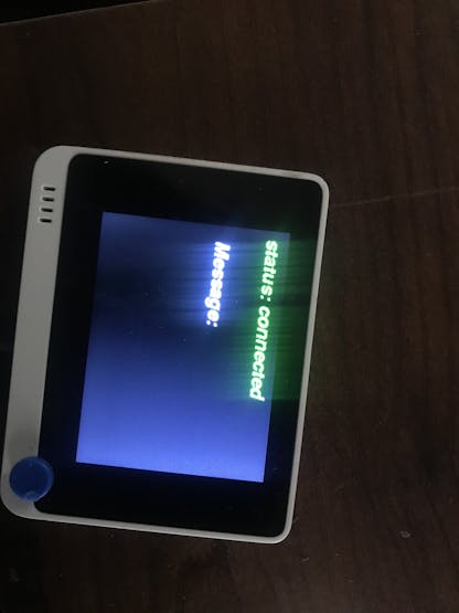
ESP32 BLE
- Now we have to send messages from ESP32 to the Wio terminal. - Use the following code to test if messages are received smoothly.#include <BLEDevice.h> //Header file for BLE static BLEUUID serviceUUID("E400001-B5A3-F393-E0A9-E50E24DCCA9E"); //Service UUID of Wio terminal obtained through nRF connect application static BLEUUID charUUID("6E400002-B5A3-F393-E0A9-E50E24DCCA9E"); //Characteristic UUID of wioterminal obtained through nRF connect application String My_BLE_Address = "2c:f7:f1:1b:3f:25"; //Hardware Bluetooth MAC of my wio terminal.static BLERemoteCharacteristic* pRemoteCharacteristic;BLEScan* pBLEScan; //Name the scanning device as pBLEScanBLEScanResults foundDevices;static BLEAddress *Server_BLE_Address;String Scaned_BLE_Address;boolean paired = false; //boolean variable to togge lightbool connectToserver (BLEAddress pAddress){ BLEClient* pClient = BLEDevice::createClient(); Serial.println(" - Created client"); // Connect to the BLE Server. pClient->connect(pAddress); Serial.println(" - Connected to wio terminal"); // Obtain a reference to the service we are after in the remote BLE server. BLERemoteService* pRemoteService = pClient->getService(serviceUUID); if (pRemoteService != nullptr) { Serial.println(" - Found our service"); return true; } else return false; // Obtain a reference to the characteristic in the service of the remote BLE server. pRemoteCharacteristic = pRemoteService->getCharacteristic(charUUID); if (pRemoteCharacteristic != nullptr) Serial.println(" - Found our characteristic"); return true;}class MyAdvertisedDeviceCallbacks: public BLEAdvertisedDeviceCallbacks { void onResult(BLEAdvertisedDevice advertisedDevice) { Serial.printf("Scan Result: %s \n", advertisedDevice.toString().c_str()); Server_BLE_Address = new BLEAddress(advertisedDevice.getAddress()); Scaned_BLE_Address = Server_BLE_Address->toString().c_str(); }};void setup() { Serial.begin(115200); //Start serial monitor Serial.println("ESP32 BLE Server program"); //Intro message BLEDevice::init(""); pBLEScan = BLEDevice::getScan(); //create new scan pBLEScan->setAdvertisedDeviceCallbacks(new MyAdvertisedDeviceCallbacks()); //Call the class that is defined above pBLEScan->setActiveScan(true); //active scan uses more power, but get results faster }void loop() { foundDevices = pBLEScan->start(3); //Scan for 3 seconds to find the Fitness band while (foundDevices.getCount() >= 1) { if (Scaned_BLE_Address == My_BLE_Address && paired == false) { Serial.println("Found Device :-)... connecting to Server as client"); if (connectToserver(*Server_BLE_Address)) { paired = true; Serial.println("Hello"); break; } else { Serial.println("Pairing failed"); break; } } } }
Step 4 : Testing and downloading the library
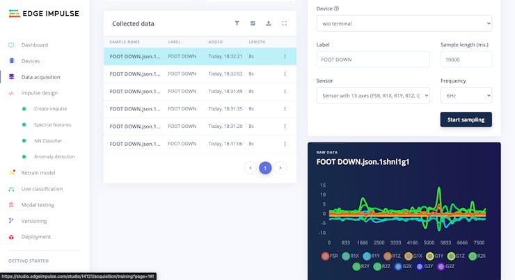
We will have three labels for each leg Foot Down, Knee Forward, Knee Backward. We will use these three labels and map the data into different Gait phases.
- Download as Arduino library. - Add this library through the Arduino IDE via: - Sketch > Include Library > Add.ZIP Library... - Examples can then be found under: - File > Examples > WIO Inferencing (Edge Impulse)
Step 5 : Sending signals to the Neosensory Buzz

After mapping the labels to different gait phases. We will assign different vibrations to the neo sensory buzz so that the patient can easily understand where exactly is their leg.
Step 7 : Connecting it with Open Exo
Check thistutorial to see how we build the exosuit.We have created a small 3d printed case to connect the MPU6050 sensors to the body.The entire code used in this tutorial is added to theGithub repository.
Improvements and conclusion
Improvements: To make our device even more versatile and user-friendly, we suggest adding a real-time motion tracking dashboard and integrating it with a foot pressure sensing system. We provide guidance on how to make these improvements in our project.
Conclusion: By following our instructions and building our device, others can contribute to improving the quality of life for people with lower limb disabilities worldwide. We hope that our open-source project will inspire others to continue building upon it and making it even better.
The article was first published in Hackaday on 10th May, 2023
cr: https://hackaday.io/project/191011-intelligent-feedback-system-for-assistive-walking
Author: Robin Kanattu Thomas


