Ultrasonic Sensor HC-SR04 With Warning LED Using Raspberry Pi Pico

In this tutorial we will learn how to use  HC-SR04 Ultrasonic sensor with Raspberry Pi Pico to measure the obstacle distance and use integrated LED as a warning. Once the distance is smaller then 10cm the LED will activate and the shorter the distance the faster the LED will blink.

Watch the video!

STEP 1
What You Will Need

What You Will Need

What You Will Need

What You Will Need

What You Will Need

What You Will Need

What You Will Need

Raspberry Pi Pico RP2040HC-SR04 Ultrasonic sensorOLED I2C DisplayBreadboardJumper wiresVisuino program: Download Visuino
STEP 2
The Circuit

The Circuit

The Circuit

Connect OLED Display pin [VCC] to Pi Pico RP2040 pin [VBUS]Connect OLED  Display pin [GND] to Pi Pico RP2040 pin [GND]Connect OLED Display pin [SDA] to Pi Pico RP2040 pin [4]Connect OLED Display pin [SCL] to Pi Pico RP2040 pin [5]Connect HC-SR04 pin [VCC] to Pi Pico RP2040 pin [VBUS]Connect HC-SR04 pin [GND] to Pi Pico RP2040 pin [GND]Connect HC-SR04 pin [Trigger] to Pi Pico RP2040 pin [3]Connect HC-SR04 pin [Echo] to Pi Pico RP2040 pin [2]
STEP 3
Start Visuino, and Select the Raspberry Pi Pico (RP2040) Board Type

Start Visuino, and Select the Raspberry Pi Pico (RP2040) Board Type

Start Visuino, and Select the Raspberry Pi Pico (RP2040) Board Type

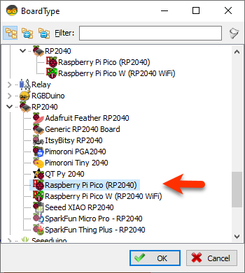
Start Visuino as shown in the first picture Click on the "Tools" button on the Arduino component (Picture 1) in Visuino When the dialog appears, select "Raspberry Pi Pico (RP2040)" as shown on Picture 2

STEP 4
In Visuino Add & Set Components

In Visuino Add & Set Components

In Visuino Add & Set Components

In Visuino Add & Set Components

In Visuino Add & Set Components

In Visuino Add & Set Components

In Visuino Add & Set Components

In Visuino Add & Set Components

In Visuino Add & Set Components

In Visuino Add & Set Components

In Visuino Add & Set Components

In Visuino Add & Set Components

In Visuino Add & Set Components

In Visuino Add & Set Components

Add "Ultrasonic Ranger" componentAdd "Analog Multi Source" componentSelect "MultiSource1" and in the properties window set "Output Pins" to 3Add "Map Range Analog" component

"Map Range Analog" component will transform our distance from the ultrasonic sensor to the Frequency of the LED blinking

Select "MapRange1" and in the properties window set "Input Range" > "Max" to 10 <<this means that we will monitor the distance from 0 cm to 10 cmand "Output Range" > "Max" to 1 and "Output Range" > "Minn" to 5 << this means that the blinking frequency of the LED will be from 1Hz to 5HzAdd "Compare Analog Value" componentSelect "Compare1" and in the properties window set "Compare Type" to CtSmaller and "Value" to 10 <<This means if the Input value is smaller then 1o the output will be TrueAdd "Pulse Generator" componentSelect "PulseGenerator1" and in the properties window select "Enabled" and click on the pin icon and select "Boolean SinkPin"Select "PulseGenerator1" and in the properties window select "Frequency" and click on the pin icon and select "Float SinkPin"Add "OLED I2C" componentDouble click on the "DisplayOLED1" and in the "Elements" window drag "Draw Text" to the left side and in the Properties window set "Size" to 2 and "Text" to DistanceDrag "Text Field" to the left side and in the Properties window set "Size" to 2 and "Y" to 30Close the "Elements" window
STEP 5
In Visuino Connect Components
Connect "UltrasonicRanger1" pin [Echo] to Raspberry Pi Pico/RP2040 digital pin [2]Connect "UltrasonicRanger1" pin [Ping-Trigger] to Raspberry Pi Pico/RP2040 digital pin [3]Connect "UltrasonicRanger1" pin [Out] to "MultiSource1" pin [In]Connect "MultiSource1" pin [0] to "DisplayOLED1" > "TextField1" pin [In]Connect "MultiSource1" pin [1] to "Compare1" pin [In]Connect "MultiSource1" pin [2] to "MapRange1" pin [In]Connect "Compare1" pin [Out] to "PulseGenerator1" pin [Enabled]Connect "MapRange1" pin [Out] to "PulseGenerator1" pin [Frequency]Connect "PulseGenerator1" pin [Out] to Raspberry Pi Pico/RP2040 LED pin [Digital]Connect "DisplayOLED1" pin I2C [Out] to Raspberry Pi Pico/RP2040 pin I2C [In]
STEP 6
Generate, Compile, and Upload the Project

Generate, Compile, and Upload the Project

In Visuino, at the bottom click on the "Build" Tab, make sure the correct port is selected, then click on the "Compile/Build and Upload" button.

STEP 7
Play

If you power the Raspberry Pi Pico/RP2040 the OLED Display will start to show the distance of the obstacle detected by ultrasonic sensor and if the distance is smaller then 10cm the integrated LED on the Raspberry Pi Pico/RP2040 will be activated. The LED will blink faster if the distance is smaller.

Congratulations! You have completed your project with Visuino. Also attached is the Visuino project, that I created for this tutorial, you can download it and open it in Visuino: https://www.visuino.com

icon pico-ultrasonic-oled.zip 2KB Download(0)
License
All Rights
Reserved
licensBg
0