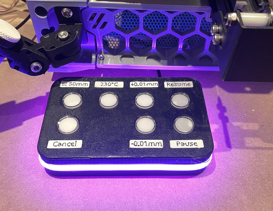
Hi there, in this project I am going to be walking though how I built a macro pad for my 3D printer.
My Ender 3 runs Klipper and I have the printer in an enclosure with the electronics outside the enclosure. This means it’s annoying to go back and forth from the printer to the electronics or my computer to enter commands, like pre-heat, or pause/cancel a print. I wanted to make it easier to enter those commands without leaving the printer.
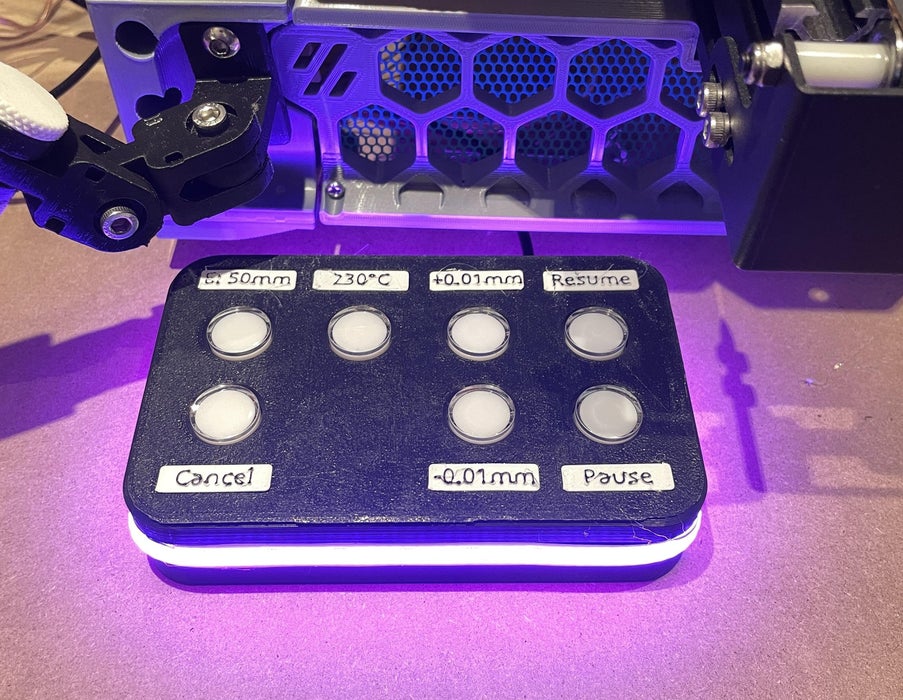
Enter, this macro pad. It has 7 gcode macros programmed in for the commands I use the most and want to be easily accessible.
There is one prerequisite for this macro pad, your 3D printer must be running Klipper. I’m sure there is a way to do this in marlin or the like but I have no idea how.
You also should be comfertable with using SSH to acess your printer's pi, working with .cfg files, and working with your slicer.
Also a disclosure up here, all the parts for this project were provided to me for free by DFRobot. They had no other involvement in the project or anything related to it (this Instructable), I told them the parts I wanted and they sent them over for free. They even sent a few I didn’t end up using.
Supplies
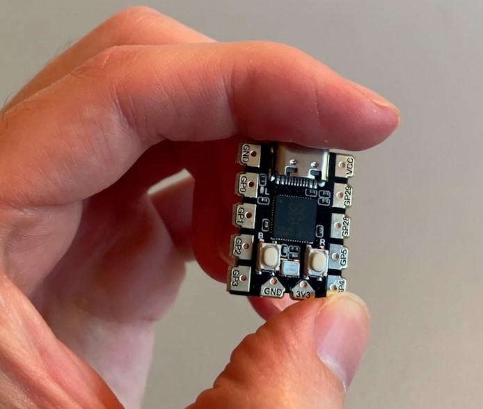
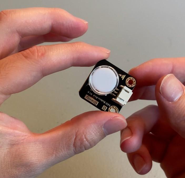
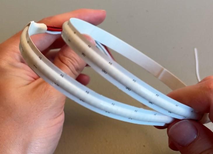
Parts!
Again, the electronics for this project were provided to me for free by DFRobot. (I have some alternatives listed too) but none of these links are affiliate links.
---
After posting DF Robot did reach out and provide me a coupon code you can use. It is valid until October 1st, 2024.
You can get $5 off of an order of $50
Coupon link: https://www.dfrobot.com/coupon-320.html
---
a. RPI pico
2. Light up push button
b. Any push button
3. LED strip
c. Any addressable LED strip
4. USB cord
5. filament (I used ASA)
6. M3 screws
d. 14 that are 4-8mm
e. 4 that are up to 16mm
7. A small piece of protoboard
Tools
1. 3D printer
2. Soldering iron
3. Wire cutters
4. Wire strippers
5. Hot glue gun
6. Screwdriver
Step 1: Slicing and Printing
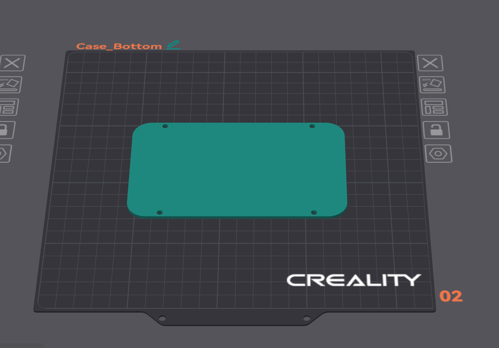
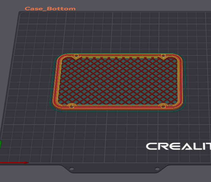
The first step for me is going to be printing off the case. This case is a bit more complex to slice that some of my other designs but I’ll walk you through it. You can grab all the models on printables.
I printed the case in with ASA filament but really anything should work just fine, but as I plan to install this inside of my enclosure, and over time PLA could sag.
I also printed all of these on a textured PEI build plate as the texture on the surface looks really nice.
First is the top of the case. Print this face down. Or so the holes for the buttons are on the build plate.
Next is the bottom of the case. I'm using Orca Slicer but it should be a similar process with any of the other similar slicers, like Prusa.
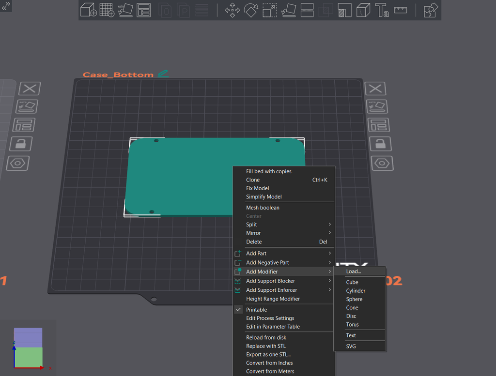
Make sure the bottom is oriented flat on the bed, and then right click on it and select "Add Modifier" and choose "Load...", load in the bottom modifier object. It should align the two parts properly, with the modifier in center of the bottom cover. Check the attached images for the positioning.
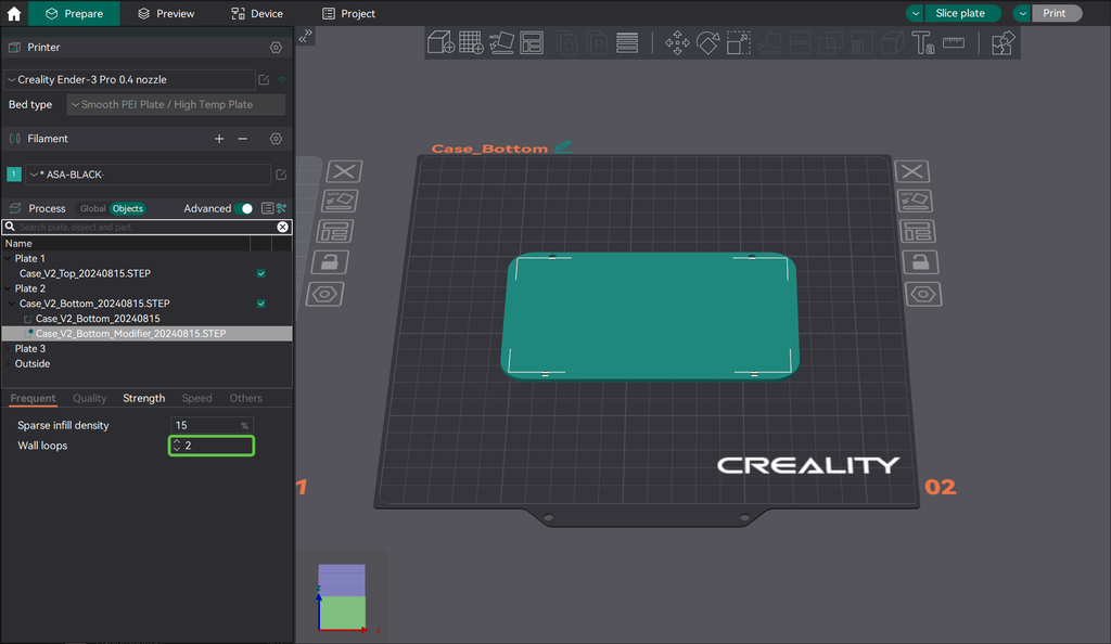
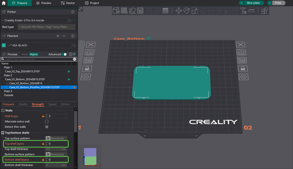
In Orca on the left, click on the "Objects" tab and under the settings, set it to have 3 wall loops, and in the strength tab zero top and bottom layers, again, take a look at some of the images for these settings. This will create a mesh of just infill when you slice it. I went for 15% grid infill.
For the labels, I have included all the ones I used but I have also included a blank one that you can put whatever text you want on it. Just use the text tool and deboss it by .4mm or 2 layers. I printed these in white PLA and when over the top layer with a black sharpie to make the text standout.
Step 2: Setting Up the MCU
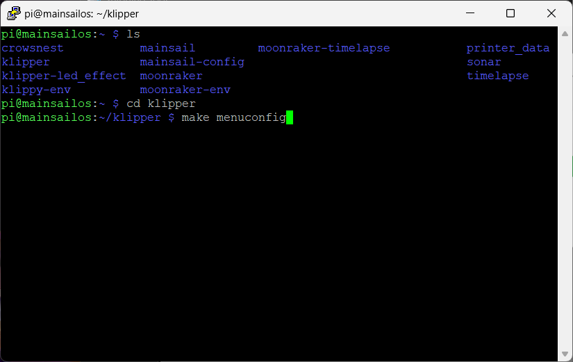
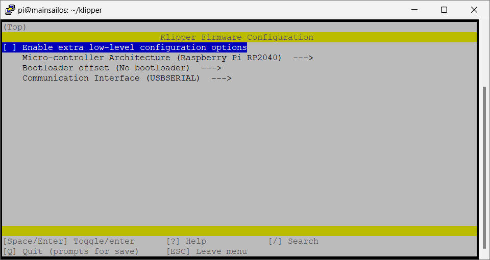
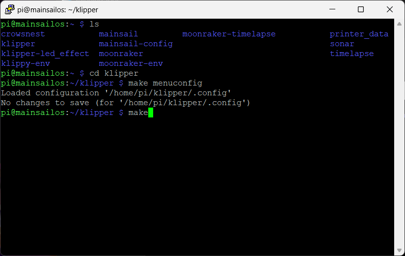
You likely have already done the next steps before when setting up your printers main board as the MCU for your printer. So, hopefully this is a bit familiar.
The first step is to connect to your printer using SSH, I typically use PuTTy to do this from windows but I just learned that within power shell you can use the command “ssh [email protected]” to connect to your printer as well. Just replace the pi with your user name and the ip with the ip for your printer. For a Mac or Linux machine you’ll have to look up how to ssh, as I've never done it.
Once connected I like to use the ‘ls’ command to list all the directories where you are then the ‘cd folder’ to move to where you want to be, just change out the 'folder' with the one you want. For me it was just 'cd klipper'
You need to make your way to the ‘klipper’ directory.
Once you are in the klipper folder, type in this command
make menuconfig
This will open up the menu for creating the firmware file for the rp2040. Use the arrow keys to move around and enter to select. Change the architecture to RP2040 and leave the rest the same.
Press 'Q' to exit and you will be prompted to save.
Now just type in the command
make
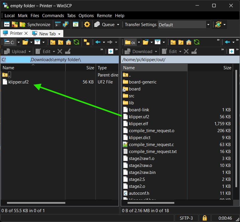
And you should start seeing some output, wait for that to finish and eventually you should notice a file output. Take note of that location, we need to get that file from the pi to the local machine you are working on.
I use WinSCP to connect to the pi, again logging in to the ip with my pi user name and password.
Then navigate to the ‘out’ folder and find the file you need. Then you can copy and paste it to your local machine. I put it in my downloads folder.
Now, while holding down the boot button on the rp2040 plug it into your computer, it should show up like a flash drive. Drag and drop the file we just got into the rp2040. It should eject itself after a moment. (Also this process is totally the same for any rp2040 based controller).
Take the rp2040 and plug it into the pi that is running Klipper.
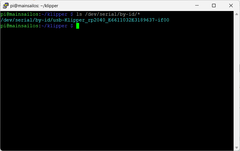
Into the ssh window type in the following command to list the usb devices.
ls /dev/serial/by-id/*
Copy the one that has rp2040 in the name and put it somewhere safe for later.
Your rp2040 is now recognized by your Klipper printer, you can’t do anything with it yet but that will come in a few steps.
Step 3: Mechanical Assembly
Once the parts finish printing you should be set to start putting everything together.
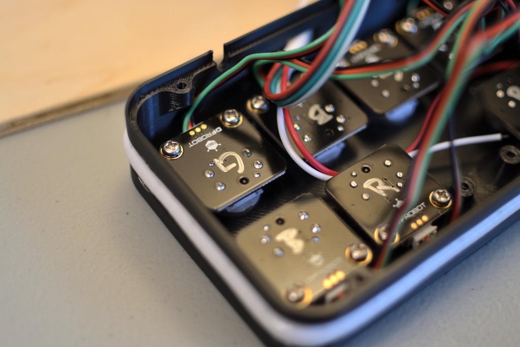
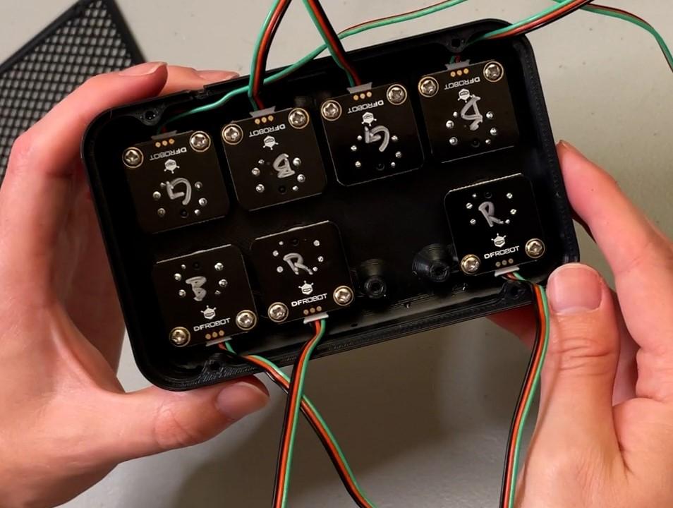
I used some short M3 screws to attach each button to top of the case. If you care, make sure the button colors are in the order you want. I went through and transferred the color to the back of the PCB so I could tell more easily what color each one is. Make sure to install the wire harnesses provided with the buttons before installing the buttons as there isn't enough space to do it after.
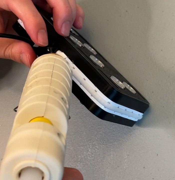
Once all the buttons have been installed, I install the LEDs. First I peeled off the sticky back that is on the LED strips as I’ve had mixed luck with others in the past, and for the life of me I could not get the paper backing off of this one.
To start, feed the start of the strip though the hole in the top and line it up where it should start, then slowly work around the case hot gluing it in place as you go. Make sure to keep it flat and tight against the case. Hot glue works great and is somewhat removable, if you need to make changes in the future.
At the end, find where you want the strip to stop and clip it with some wire cutters, the chances you hit a diode on this strip are super high, but the rest of the strip will be totally usable with a bit of soldering to the exposed pads on the back of the strip.
Hot glue the end of the strip in place.
Step 4: Electrical Assembly
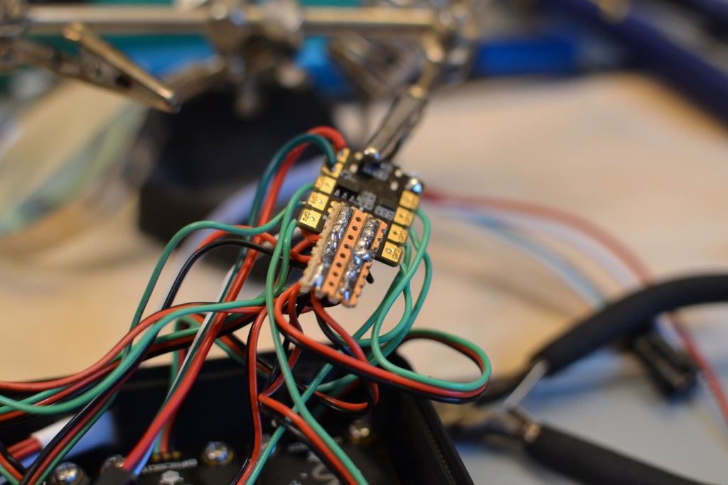
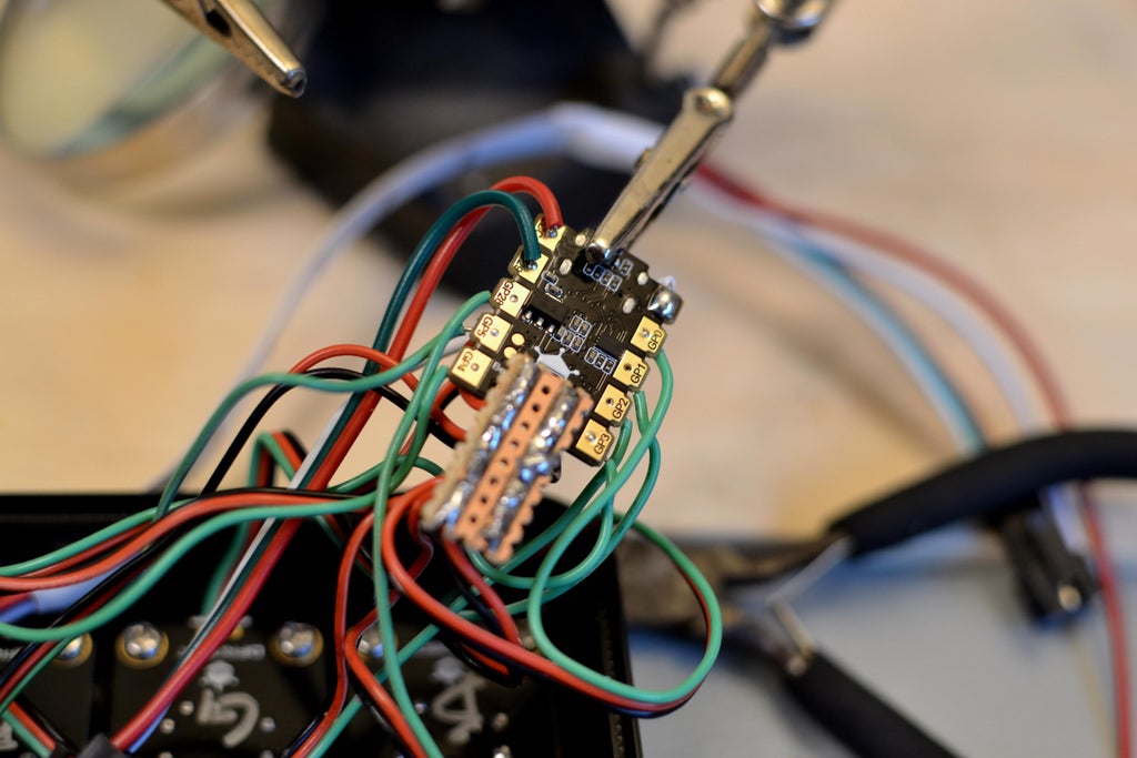
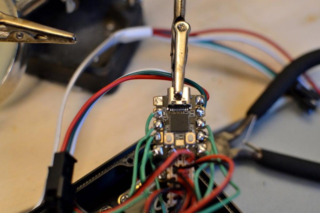
The circuit diagram for this one is included above, the actual wiring looks kind of scary but it’s pretty simple once you strip out all the power and ground wires.
The signal wire from the 7 buttons need to be connected to one of the 8 pads on the rp2040 and the data wire from the LEDs goes to the last one.
Then each just needs a power (3.3v for the buttons and 5v for the LEDs) and ground wire.
I started with the LED harness as I used the provided connector and wired the power to 5v the ground to the ground by the usb port and the signal wire (green) to pad 29 on the 2040
For the buttons, because there are so many there will not be enough power and ground wires for each to have its own. To solve this I took the center pin out of a set of three pin headers, and soldered that to the 3.3v and ground pads at the bottom of the board. Then I used a small piece of protoboard that was 3 holes wide by 10 holes long to attach to the pin headers. Take a look at the images, this is a bit hard to explain.
I then connected each of the power and ground wires for the buttons to that protoboard and wired the third wire (the signal wire) to the pads on the 2040.
I used the provided wire harnesses but cut off the black connectors and used the free wires to connect to the controller.
Now plug in the usb-c cord, and I like to wrap the MCU in some blue tape just to prevent any shorts as there are not any hard mounting bosses in this case for the MCU. In fact before I was in contact with DFRobot I fully intended to use the Rpi pico instead, other than leaving about 20 IO pins unused it would work great and I think I am planing to make another with the pico to control things like my Bento box air filter, lights, and even some of the fans on the printer.
With the MCU set, screw the bottom on using the remaining M3 screws.
Not too bad eh? Now if you plug in the controller to a usb port and push a button it should light up! Check all of them and fix any wiring issues that you might have. The led strip wont turn on because it doesn’t have a data signal but that’s ok for now.
Step 5: Programing/Configuring
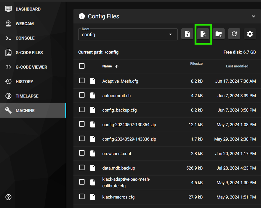
Programming for this project is pretty simple but it’s good to take the time to get it right because the end result is the moving of a physical object (your printer). So when testing the buttons be sure to keep clear of your printer so it doesn’t bite you.
In your config section create a new file and call it what ever you want. I called mine RP2040.cfg
This file will hold all the code for the macro pad so its easy to connect/disconnect it if ever needed.
At the top of the file create an MCU section, it will look like this
[mcu pico]
serial: /dev/serial/by-id/usb-Klipper_rp2040_E6611032E3189637-if00
Make sure to replace the long ID string with the ID you got from setting up the firmware, and I called mine pico but it can be what ever you want.
To start, I set up all the buttons as gcode buttons, this is done by entering the following code for each button with the correct GPIO pin, and changing the message, check the test code file attached.
[gcode_button Test_Button1]
pin: ^!pico:gpio0
press_gcode:
RESPOND TYPE=echo MSG='Button 0'
If you get weird behavior, try chainging the ^ or the ! at the begining of the pin deffinition, these change how the pin behaves.
For the LEDs I set them up to show up as purple, because I like purple, also it’ll tell you if the RGB order is correct, as only two of the three should be on, and the different levels will tell you that.
#Led strip, defaults to purple
[neopixel Button_Pad]
pin: pico:gpio29
chain_count:150
color_order: GRB
initial_RED: .10
initial_GREEN: .0
initial_BLUE: .10
Now at the top of your printer.cfg file add an include statement for the file you just made. Save and restart Klipper.
[include RP2040.cfg]
If you get any errors check your serial ID, otherwise the LED strip should light up and when you press a button you should see the the echo messages in the console. Take the time now to correct any GPIO issues you might have. I also take the time to arrange them so from the top of the file to the bottom they work across the top row then back across the bottom row.
With all the buttons correct I swap out the echo for the gcode commands I want. I included my file at the bottom but make sure to make any changes you want.
For testing, make sure to keep one hand on the estop so you don't break anything.
That’s pretty much it!
It should be working
Step 6: Going Farther and Alternate Parts
There are a few options for alternate parts if you don't want to use DFRobot parts or want to use any parts you have on hand.
For the Beetle RP2040 any RP2040 based board would work such as the raspberry pi pico, or the like.
For the buttons, any button should work. You may need to make changes in the cfg file for a normally closed button as the ones use are normally open.
For the LED strip, any standard 5v neopixel or dot star led strip should work.
If you want to step up the LED to do more, there are a few LED animation libraries out there including one that does a progress bar (link) and one that adds simple animations like breathing and chases (link).
I’m not sure how far you will be able to get with the animations on this MCU as when I run them I am using about 90% of its processing power…
Step 7: Conclusion
You made it! If you're here, consider subscribing to my channel over on YouTube. I usually post companion videos to Instructables.
Check out my Instagram @tinyboatproductions, sometimes I tease projects over there before I post anything.
Also if you run into any issues or have questions, or ideas for improvement please leave a comment!
I look forward to seeing you next time, thanks for reading.
This article was first published on Instructables on Aug 19th, 2024
cr: https://www.instructables.com/3D-Printer-Macro-Pad/
Author: tinyboatproductions


