In this tutorial, we will explore various ways to use an LED tactile button with Visuino and Arduino.Example 1
: The LED on the button will turn ON or OFF with each button press.Example 2: The LED will oscillate between ON and OFF states when you press the button to activate it.Example 3: The LED will gradually dim or brighten when you press the button.Example 4: With each press, the LED's brightness will increase. Once it reaches maximum brightness, it will reset and start from the lowest brightness.Example 5: Pressing the button will toggle the LED's blinking state—starting or stopping the blink.
Watch the video!
At the bottom under the Step "Play" you will find the project files of all examples.
Arduino board (or any other board)BreadboardTactile Button2X 1K ohm resistorJumper wiresVisuino program: Download Visuino
Connect Arduino Digital pin [2] to Tactile Button on the breadboard and to the Resistor1Connect other side of the Resistor1 to the breadboard pin [GND]Connect Other pin of the Tactile Button to the breadboard positive pin [5V]Connect Arduino pin [5V] to breadboard positive pin [Red line]Connect Arduino pin [GND] to breadboard negative pin [Black line]
Connect Arduino Digital pin [3] to the Resistor2Connect Resistor2 to Tactile button side pin [+]Connect Tactile Button side pin [-] to breadboard negative pin [Black line]
Note: Most of the Tactile Buttons have a red dot on the GND pin, this way you can correctly connect it
The LED on the button will turn ON or OFF with each button press.
Add "Debounce Button" componentAdd "Toggle Flip-Flop" componentConnect Arduino digital pin [2] to "Button1" pin [In]Connect "Button1" pin [Out] to "TFlipFlop1" pin [Clock]Connect "TFlipFlop1" pin [Out] to Arduino digital pin [3]
Upload the project like described in the step "Generate, Compile, and Upload the Arduino Code"
The LED will oscillate between ON and OFF states when you press the button to activate it.
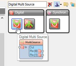
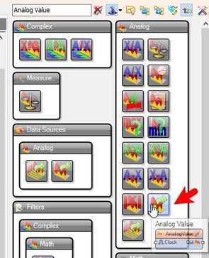
Add "Debounce Button" componentAdd "Toggle Flip-Flop" componentAdd "Digital Multi Source" componentAdd "Sine Analog Generator" componentAdd "Detect Edge" componentAdd "Analog Value" componentAdd "Analog Multi-Source Merger" component
Select "SineAnalogGenerator1" and in the properties window set "Enabled" to False and "When Disabled" > "Reset" to True, select "Enabled" and click on the pin Icon and select "Boolean SinkPin"Select "DetectEdge1" and in the properties window set "On Rising/True" to False
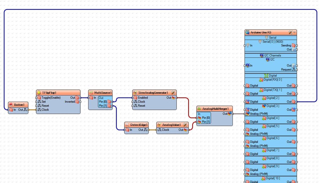
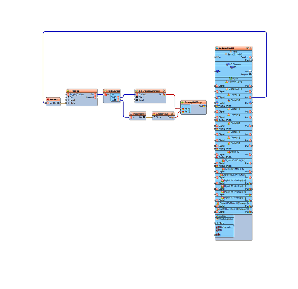
Connect Arduino digital pin [2] to "Button1" pin [In]Connect "Button1" pin [Out] to "TFlipFlop1" pin [Clock]Connect "TFlipFlop1" pin [Out] to "MultiSource1" pin [In]Connect "MultiSource1" pin [0] to "SineAnalogGenerator1" pin [Enabled]Connect "MultiSource1" pin [1] to "DetectEdge1" pin [In]Connect "DetectEdge1" pin [Out] to "AnalogValue1" pin [Clock]Connect "SineAnalogGenerator1" pin [Out] to "AnalogMultiMerger1" pin [0]Connect "AnalogValue1" pin [Out] to "AnalogMultiMerger1" pin [1]Connect ""AnalogMultiMerger1" pin [Out] to Arduino Analog PWM pin [3]
Upload the project like described in the step "Generate, Compile, and Upload the Arduino Code"
The LED will gradually dim or brighten when you press the button.
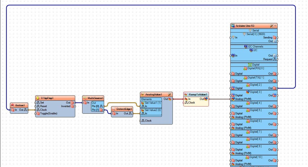
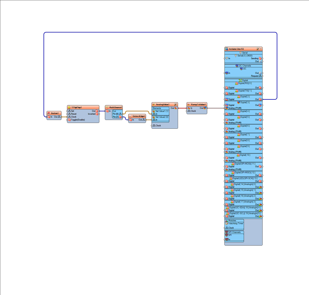
Add "Debounce Button" componentAdd "Toggle Flip-Flop" componentAdd "Digital Multi Source" componentAdd "Detect Edge" componentAdd "Analog Value" componentAdd "Ramp To Analog Value" component
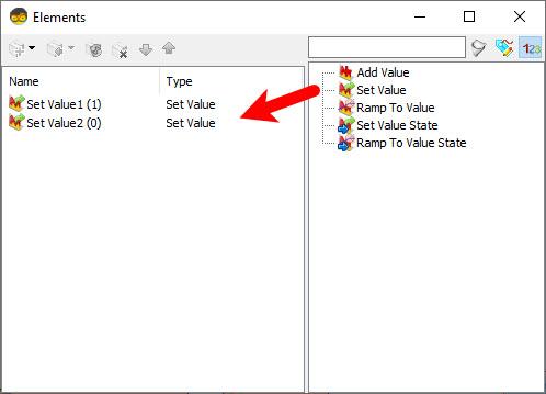
Select "DetectEdge1" and in the properties window set "On Rising/True" to FalseDouble click on the "AnalogValue1" and in the Elements window drag "Set Value" to the left side and in the properties window set "Value" to 1Drag another "Set Value" to the left side and close the Elements windowSelect "RampToValue1" and in the properties window set "Slope (Sec)" to 0.5
Note: to change the Dim or Brightness time adjust the "Slope (Sec)" value according to your needs
Connect Arduino digital pin [2] to "Button1" pin [In]Connect "Button1" pin [Out] to "TFlipFlop1" pin [Clock]Connect "TFlipFlop1" pin [Out] to "MultiSource1" pin [In]Connect "MultiSource1" pin [0] to "AnalogValue1" > "Set Value 1" pin [In]Connect "MultiSource1" pin [1] to "DetectEdge1" pin [In]Connect "DetectEdge1" pin [Out] to "AnalogValue1" > "Set Value 2" pin [In]Connect "AnalogValue1" Pin [Out] to "RampToValue1" Pin [In]Connect ""RampToValue1" pin [Out] to Arduino Analog PWM pin [3]
Upload the project like described in the step "Generate, Compile, and Upload the Arduino Code"
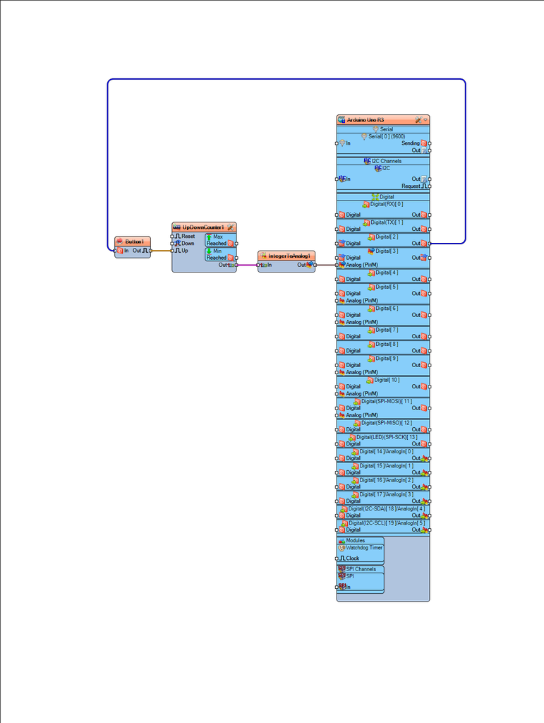
With each press, the LED's brightness will increase. Once it reaches maximum brightness, it will reset and start from the lowest brightness.
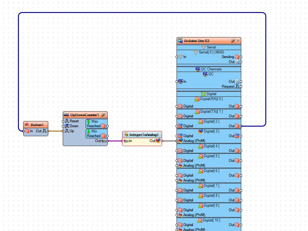
Add "Debounce Button" componentAdd "Up/Down Counter" component
Note: you can also use just the "Counter" component
Add "Integer To Analog" component
Select "UpDownCounter1" and in the properties window set "Max" > "Value" to 5 < Connect Arduino digital pin [2] to "Button1" pin [In]Connect "Button1" pin [Out] to "UpDownCounter1" pin [Up]Connect "UpDownCounter1" Pin [Out] to "IntegerToAnalog1"Connect ""IntegerToAnalog1" pin [Out] to Arduino Analog PWM pin [3] Upload the project like described in the step "Generate, Compile, and Upload the Arduino Code"
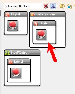
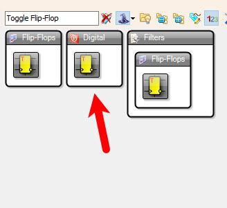
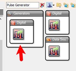
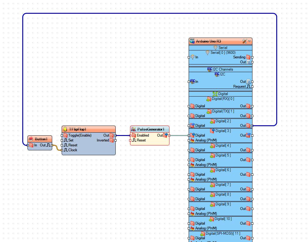
Pressing the button will toggle the LED's blinking state—starting or stopping the blink.
Add "Debounce Button" componentAdd "Toggle Flip-Flop" componentAdd "Pulse Generator" component
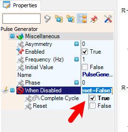
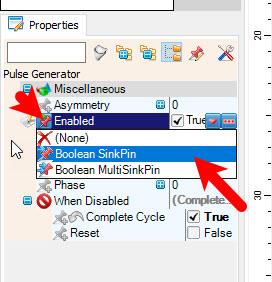
Select "PulseGenerator1" and in the properties window set "Enabled" to False and "When Disabled" > "Complete Cycle" to True, select "Enabled" and click on the pin Icon and select "Boolean SinkPin"
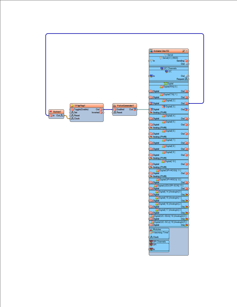
Connect Arduino digital pin [2] to "Button1" pin [In]Connect "Button1" pin [Out] to "TFlipFlop1" pin [Clock]Connect "TFlipFlop1" pin [Out] to "PulseGenerator1" pin [Enabled]Connect "PulseGenerator1" pin [Out] Arduino digital pin [3]
Upload the project like described in the step "Generate, Compile, and Upload the Arduino Code"
Congratulations! You have completed your project with Visuino. Also attached are the Visuino project files for each example, that I created for this tutorial, you can download it and open it in Visuino: https://www.visuino.eu


