
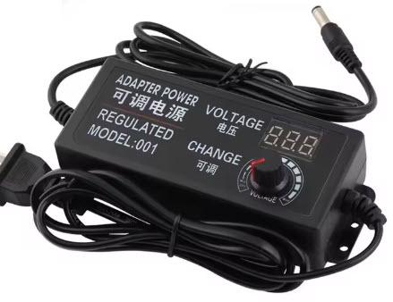
This tutorial shows how to use the INA226 Voltmeter with a GC9A01 Display in Visuino to measure and display voltage in real time. The project reads voltage data from the INA226 sensor and visualizes it on the GC9A01 circular display using graphical elements.
You can download the project file at the bottom.
Watch the video!


Note: If you plan to use a lot of graphics on the display or more sensore/modules then you might need a board with larger memory like Arduino UNO R4 WiFi

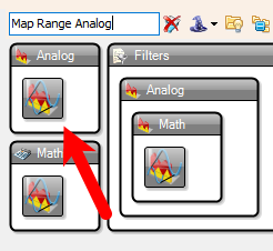
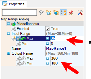
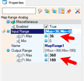
Select "MapRange1" and in the properties window set "Input Range" > Max to 36 and "Input Range" > Min to 0 and "Output Range" > Max to 360 and "Output Range" > Min to 180
Note:Because INA226 can measure from 0-36V and display "0" is at 180 degrees and ranges up to 360 degrees, We are using Map Range Analog to convert values from 0-36 to 180-360.
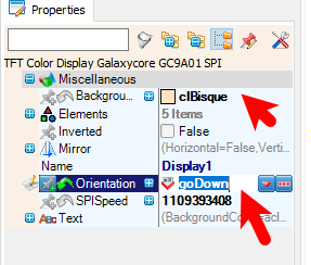


Select "Display1" and in the properties window set "Background Color" to clBisque and "Orientation" to goDown
Step 1: Open the Display Configuration
Double-click on the Display1 component in the diagram.This will open the Elements window for the display.Step 2: Add and Configure Graphical Elements
Add 2X "Draw Angled Line" elementAdd "Text Field" elementAdd "Draw Scene" elementAdd "Text Field" elementAdd "Draw Ellipse" element
Draw Ellipse, and Text Field. Here’s how to configure each one:
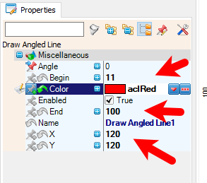
Draw Angled Line1
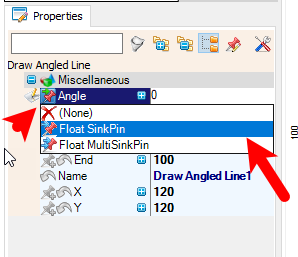
In the Elements window, locate the Draw Angled Line1 element.In the Properties window, configure the following:Set Begin to 11.Set End to 100.Set X to 120.Set Y to 120.Set Color to aclRedSelect "Angle" and click on the pin icon and select "Float SinkPin"
Draw Angled Line2
In the Elements window, locate the Draw Angled Line2 element.In the Properties window, configure the following:Set Begin to 11.Set End to 100.Set X to 120.Set Y to 120.Set Color to aclBisqueSelect "Angle" and click on the pin icon and select "Float SinkPin"
Text Field1
In the Elements window, locate the Text Field1 element.In the Properties window, configure the following:Set Size to 2.Set HorizontalAlign to thaCenter (center alignment).Set X to 30.Set Y to 130.Set FillColor to aclBisqueSet Color to aclBlueConnect the ClockInputPin to MultiSource1 pin [Pin 5].Connect the InputPin to VoltageCurrentPower1 pin [Bus Voltage (V)].Draw Scene1
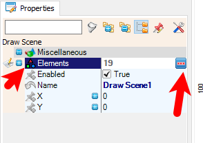
In the Elements window, locate the Draw Scene1 element.In the properties window select "Elements" and click on the 3 dots buttonIn the Elements window add 19X "Draw Angled Line" ElementFor each "Draw Angled Line" Element set the properties:Draw Angled Line1
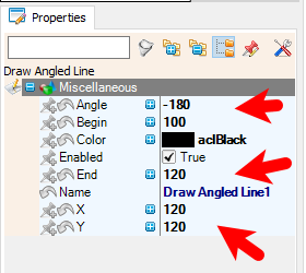
Name: Draw Angled Line1Properties:Begin: 100 (starting point of the line).Angle: -180 (angle of the line in degrees).X: 120 (X-coordinate of the line's center).Color: blackEnd: 120 (ending point of the line).Y: 120 (Y-coordinate of the line's center).Draw Angled Line2
Name: Draw Angled Line2Properties:Begin: 100.Angle: -170.X: 120.Color: blackEnd: 120.Y: 120.Draw Angled Line3
Name: Draw Angled Line3Properties:Begin: 100.Angle: -160.X: 120.Color: blackEnd: 120.Y: 120.Draw Angled Line4
Name: Draw Angled Line4Properties:Begin: 100.Angle: -150.X: 120.Color: blackEnd: 120.Y: 120.Draw Angled Line5
Name: Draw Angled Line5Properties:Begin: 100.Angle: -140.X: 120.Color: blackEnd: 120.Y: 120.Draw Angled Line6
Name: Draw Angled Line6Properties:Begin: 100.Angle: -130.X: 120.Color: blackEnd: 120.Y: 120.Draw Angled Line7
Name: Draw Angled Line7Properties:Begin: 100.Angle: -120.X: 120.Color: blackEnd: 120.Y: 120.Draw Angled Line8
Name: Draw Angled Line8Properties:Begin: 100.Angle: -110.X: 120.Color: blackEnd: 120.Y: 120.Draw Angled Line9
Name: Draw Angled Line9Properties:Begin: 100.Angle: -100.X: 120.Color: blackEnd: 120.Y: 120.Draw Angled Line10
Name: Draw Angled Line10Properties:Begin: 100.Angle: -90.X: 120.Color: blackEnd: 120.Y: 120.Draw Angled Line11
Name: Draw Angled Line11Properties:Begin: 100.Angle: -80.X: 120.Color: blackEnd: 120.Y: 120.Draw Angled Line12
Name: Draw Angled Line12Properties:Begin: 100.Angle: -70.X: 120.Color: blackEnd: 120.Y: 120.Draw Angled Line13
Name: Draw Angled Line13Properties:Begin: 100.Angle: -60.X: 120.Color: blackEnd: 120.Y: 120.Draw Angled Line14
Name: Draw Angled Line14Properties:Begin: 100.Angle: -50.X: 120.Color: blackEnd: 120.Y: 120.Draw Angled Line15
Name: Draw Angled Line15Properties:Begin: 100.Angle: -40.X: 120.Color: blackEnd: 120.Y: 120.Draw Angled Line16
Name: Draw Angled Line16Properties:Begin: 100.Angle: -30.X: 120.Color: blackEnd: 120.Y: 120.Draw Angled Line17
Name: Draw Angled Line17Properties:Begin: 100.Angle: -20.X: 120.Color: blackEnd: 120.Y: 120.Draw Angled Line18
Name: Draw Angled Line18Properties:Begin: 100.Angle: -10.X: 120.Color: blackEnd: 120.Y: 120.Draw Angled Line19
Name: Draw Angled Line19Properties:Begin: 100.Angle: 0.X: 120.Color: blackEnd: 120.Y: 120.Close the Elements window
Draw Ellipse1
In the Elements window, locate the Draw Ellipse1 element.In the Properties window, configure the following:Set Width to 20.Set Height to 19.Set X to 110.Set Y to 110.Set FillColor to aclRedSet Color to aclRed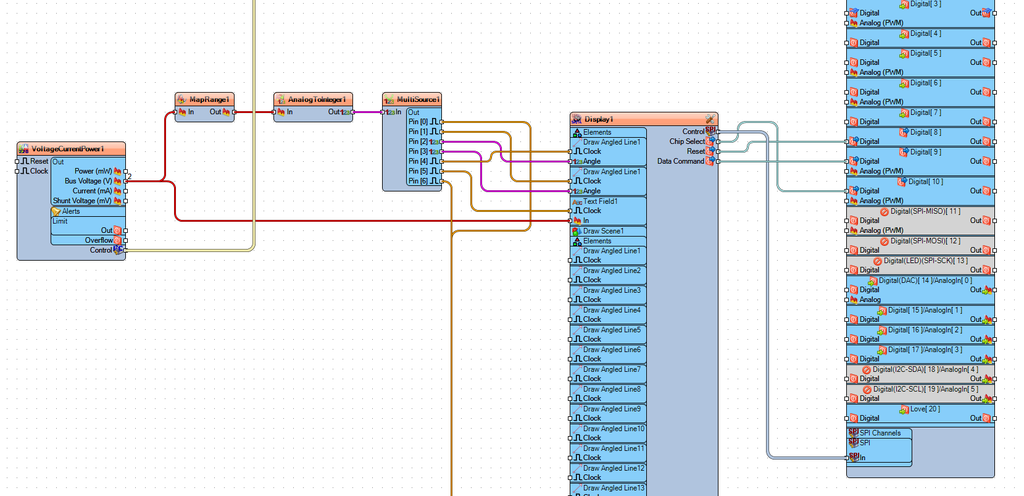
VoltageCurrentPower1 (INA226 Sensor)
Connect VoltageCurrentPower1 pin I2C [Control] to Arduino.I2CChannels[0] pin [In].Connect VoltageCurrentPower1 pin [Bus Voltage (V)] to:Text Field1 pin [In].MapRange1 pin [In].MapRange1
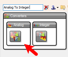
Connect MapRange1 pin [Out] to AnalogToInteger1 pin [In].AnalogToInteger1
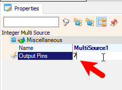
Connect AnalogToInteger1 pin [Out] to MultiSource1 pin [In].MultiSource1
Connect MultiSource1 pin [Pin 0] to:Draw Ellipse1 pin [Clock].Connect MultiSource1 pin [Pin 1] to:Draw Angled Line2 pin [Clock].Connect MultiSource1 pin [Pin 2] to:Draw Angled Line1 pin [Clock].Connect MultiSource1 pin [Pin 3] to:Draw Angled Line2 pin [Clock].Connect MultiSource1 pin [Pin 4] to:Draw Angled Line1 pin [Clock].Connect MultiSource1 pin [Pin 5] to:Text Field1 pin [Clock].Connect MultiSource1 pin [Pin 6] to:Draw Ellipse1 pin [Clock].Display1 (GC9A01 Display)
Connect Display1 pin [ChipSelect] to Arduino.Digital pin [10]Connect Display1 pin [Reset] to Arduino.Digital pin [8]Connect Display1 pin [DataCommand] to Arduino.Digital[9]Connect Display1 pin [Control] to Arduino SPIDraw Angled Line1
Connect Draw Angled Line1 pin [Angle] to MultiSource1 pin [Pin 2].Connect Draw Angled Line1 pin [Clock] to MultiSource1 pin [Pin 4].Draw Angled Line2
Connect Draw Angled Line2 pin [Angle] to MultiSource1 pin [Pin 3].Connect Draw Angled Line2 pin [Clock] to MultiSource1 pin [Pin 1].Text Field1
Connect Text Field1 pin [In] to VoltageCurrentPower1 pin [Bus Voltage (V)].Connect Text Field1 pin [Clock] to MultiSource1 pin [Pin 5].Draw Ellipse1
Connect Draw Ellipse1 pin [Clock] to:MultiSource1 pin [Pin 0].MultiSource1 pin [Pin 6].Summary of Connections
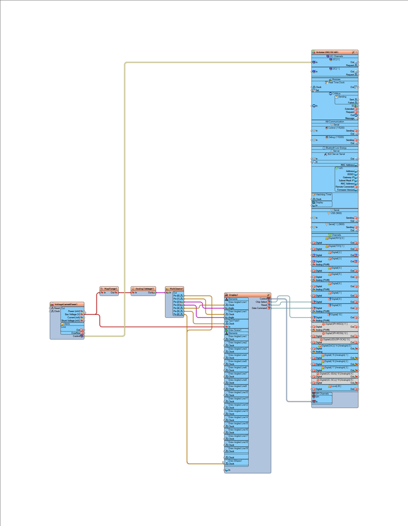
VoltageCurrentPower1 measures voltage and sends the data to Text Field1 and MapRange1.MapRange1 maps the voltage to a range of 180 to 360 and sends it to AnalogToInteger1.AnalogToInteger1 converts the value to an integer and sends it to MultiSource1.MultiSource1 distributes the value to:Draw Angled Line1 and Draw Angled Line2 for angle control.Text Field1 for displaying the voltage value.Draw Ellipse1 for graphical representation.Display1 is connected to the Arduino's digital and SPI pins for control and communication.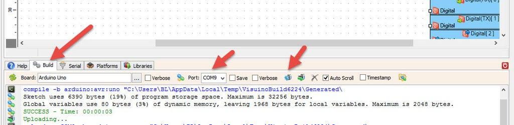
In Visuino, at the bottom click on the "Build" Tab, make sure the correct port is selected, then click on the "Compile/Build and Upload" button.
Congratulations! You have completed your project with Visuino. Also attached is the Visuino project, that I created for this Instructable, you can download it and open it in Visuino: https://www.visuino.com


