Remote Control a Linear Actuator With Visuino & Arduino

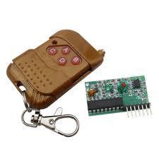
Learn how to remotely control a 12V linear actuator using a 433MHz RF module, Arduino Uno, and Visuino! In this step-by-step tutorial, we’ll use an L298N motor driver to control the actuator’s movement with ease. Perfect for DIY automation projects.

If you press the top-right or the top-left button the actuator will move fully to one direction, If you press the bottom-right or the bottom-left button the actuator will move to one direction only for the time that you press the button.

Watch the video!

STEP 1
What You Will Need

What You Will Need

What You Will Need

What You Will Need

What You Will Need

What You Will Need

What You Will Need

What You Will Need

Arduino UNO (Or any other Arduino)Linear ActuatorLN298N DC Motor Driver433 MHz RF moduleJumper wiresPower SupplyVisuino program: Download Visuino


STEP 2
The Circuit

The Circuit

Connect Remote pin [VCC] to Arduino pin [5V]Connect Remote pin [GND] to Arduino pin [GND]Connect Remote pin [D0] to Arduino digital pin [4]


Connect Power supply (batteries) pin (gnd) to motor driver controler pin (gnd)Connect Power supply (batteries) pin (+) to motor driver controler pin (+)Connect Power supply (batteries) pin (+) to Arduino pin (VIN)Connect GND from Arduino to motor driver controler pin (gnd)Connect digital pin(6) from Arduino to motor driver pin (IN1)Connect digital pin(8) from Arduino to motor driver pin (IN2)Connect Linear Actuator to the motor driver as you can see on the schematic


STEP 3
Start Visuino, and Select the Arduino UNO Board Type

Start Visuino, and Select the Arduino UNO Board Type

Start Visuino, and Select the Arduino UNO Board Type

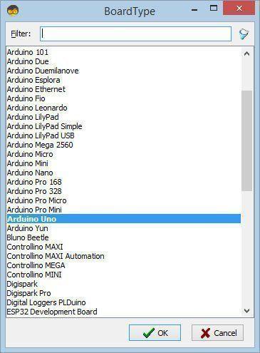
Start Visuino as shown in the first picture Click on the "Tools" button on the Arduino component (Picture 1) in Visuino When the dialog appears, select "Arduino UNO" as shown on Picture 2

STEP 4
In Visuino Add Components

In Visuino Add Components

In Visuino Add Components

In Visuino Add Components

In Visuino Add Components

In Visuino Add Components

In Visuino Add Components

In Visuino Add Components

In Visuino Add Components

Add 4X "Debounce Button" componentAdd 2X "Digital Multi Source" componentAdd "Digital (Boolean) Inverter (Not)" componentAdd 3X "Digital Multi-Source Merger" componentAdd 2X "Toggle(T) Flip-Flop" componentAdd "Analog Value" componentAdd "Speed and Direction To Speed" componentAdd "Dual DC Motor Driver Digital and PWM Pins Bridge (L9110S, L298N)" component
STEP 5
In Visuino Set Components

In Visuino Set Components

In Visuino Set Components

In Visuino Set Components

In Visuino Set Components

Select "MultiSource1" and in the properties window set "Output Pins" to 3Select "MultiSource2" and in the properties window set "Output Pins" to 3


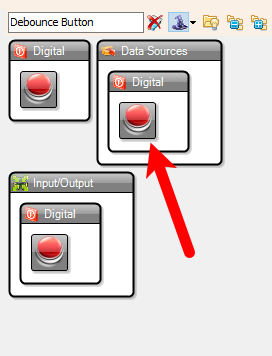
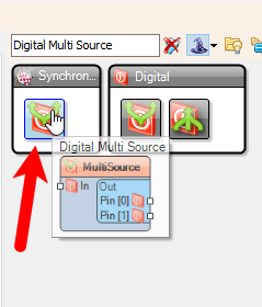
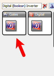
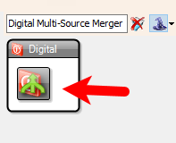
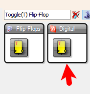
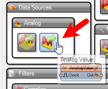
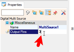
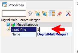
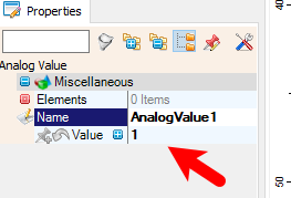
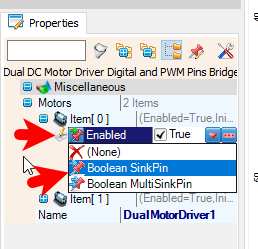
Select "DigitalMultiMerger1" and in the properties window set "Input Pins" to 3Select "DigitalMultiMerger2" and in the properties window set "Input Pins" to 3Select "AnalogValue1" and in the properties window set "Value" to 1Select "DualMotorDriver1" and in the properties window select "Motors" > "Item[ 0 ]" > "Enabled" and click on the pin Icon and select "Boolean SinkPin"
STEP 6
In Visuino Connect Components
Connect "DualMotorDriver1" > [Motors.Item[0].Direction] pin [Out] to "Arduino" pin Digital pin [8]Connect "DualMotorDriver1" > [Motors.Item[0].Speed] pin [Out] to "Arduino" pin Digital > Analog PWM pin [6]Connect "SpeedAndDirectionToSpeed1" pin [Out] to "DualMotorDriver1" > [Motors.Item[0] pin [In]Connect "AnalogValue1" pin [Out] to "SpeedAndDirectionToSpeed1" pin [speed]Connect "DigitalMultiMerger2" pin [Out] to "SpeedAndDirectionToSpeed1" pin [Reverse]Connect "Arduino" digital pin [11] to "Button1" pin [In]Connect "Button1" pin [Out] to "MultiSource1" pin [In]Connect "Arduino" digital pin [12] to "Button2" pin [In]Connect "Button2" pin [Out] to "MultiSource2" pin [In]Connect "Arduino" digital pin [9] to "Button3" pin [In]Connect "Button3" pin [Out] to "TFlipFlop1" pin [Set] and "TFlipFlop2" pin [Set]Connect "Arduino" digital pin [10] to "Button4" pin [In]Connect "Button4" pin [Out] to "TFlipFlop1" pin [Set] and "TFlipFlop2" pin [Reset]Connect "MultiSource1" pin [0] to "DigitalMultiMerger3" pin [0]Connect "MultiSource1" pin [1] to "DigitalMultiMerger2" pin [0]Connect "MultiSource1" pin [2] to "DigitalMultiMerger1" pin [0]Connect "MultiSource2" pin [Pin[0]] to "DigitalMultiMerger3" pin [1]Connect "MultiSource2" pin [1] to "Inverter1" pin [In]Connect "MultiSource2" pin [2] to "DigitalMultiMerger1" pin [1]Connect "Inverter1" pin [Out] to "DigitalMultiMerger2" pin [1]Connect "DigitalMultiMerger1" pin [Out] to "DualMotorDriver1" > [Motors.Item[0] pin [Enabled]Connect "DigitalMultiMerger2" pin [Out] to "SpeedAndDirectionToSpeed1" pin [Reverse]Connect "DigitalMultiMerger3" pin [Out] to "TFlipFlop1" pin [Reset]Connect "TFlipFlop1" pin [Out] to "DigitalMultiMerger1" pin [2]Connect "TFlipFlop2" pin [Out] to "DigitalMultiMerger2" pin [2]
STEP 7
Generate, Compile, and Upload the Arduino Code

Generate, Compile, and Upload the Arduino Code

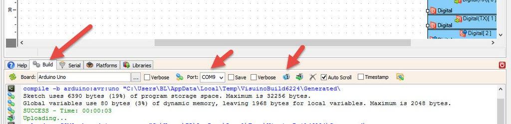
In Visuino, at the bottom click on the "Build" Tab, make sure the correct port is selected, then click on the "Compile/Build and Upload" button.

STEP 8
Play

If you power the Arduino module and press the buttons on the remote control the Linear Actuator will start to move.

Congratulations! You have completed your project with Visuino. Also attached is the Visuino project, that I created for this tutorial, you can download it here and open it in Visuino: https://www.visuino.eu

icon Linear-Actuator-Remote.zip 2KB Download(0)
License
1
BY
licensBg
0