Building a Mobile Robot with an Integrated Robotic Arm Using Arduino and Bluetooth Control

In this tutorial, we’ll learn how to build the mobile robot arm Arm, a Bluetooth-controlled robot with a robotic arm, both controlled wirelessly via a custom Android app. The Arm combines mobility and manipulation, allowing it to move around and interact with objects. This guide covers everything from designing, assembling the Arm robot, wiring the electronics, programming the Arduino, and developing an intuitive app using MIT App Inventor.
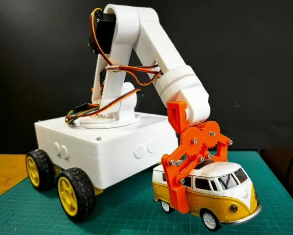
The mobile robot Arm is an upgraded project that combines two of our previous builds: a Bluetooth-controlled mobile robot, and the Arm, a 6-DOF robotic arm. Mounted on a mobile platform, the Arm can be controlled wirelessly using sliders in the app to move each axis of the arm. Additionally, the “Save” button allows recording specific positions, enabling the robot to execute automated tasks by replaying these steps. This versatile integration is perfect for DIY enthusiasts, offering a hands-on approach to robotics and automation.
Components Needed:
To build the Arm, you will need the following components:
3D-printed parts: Chassis and Arduino holder and robotic arm parts.
Chassis: Houses the motors, sensors, and Arduino board. - BUY NOW
Arduino Holder: Mounts the Arduino securely to the chassis. - BUY NOW
Motors and wheels: 4 DC motors with gearboxes and 4 wheels.
4 DC Motors with Gearboxes: Drive the robot. - BUY NOW
Electronics: Adafruit Motor Shield V1.2, Arduino Mega, - BUY NOW
HC-05 Bluetooth Module,PCA9685 servo driver, LM2596 DC-DC Step-Down Module.
Servos: 3 SG90 Micro Servos. -BUY NOW
3 MG996R Servos - BUY NOW
Accessories: Jumper wires, screws, Inserts, a battery, and a smartphone with the MIT App Inventor app installed.
Jumper Wires: For connecting components.- BUY NOW
Screws and Inserts: To securely mount parts.
Battery (e.g., 7.4V LiPo): Powers the robot.
Power Switch: Optional - BUY NOW
Step 1: Arm 3D Model Design for the Mobile Robot Arm
The first step in this project is combining designs from the previous and Arm projects. Using Autodesk Inventor, we modified the base of the Arm and merged it with the top plate (lid) design from the to create a platform that securely mounts the robotic arm onto the mobile chassis. This integration ensures that the Arm is both functional and stable.
Step 2: 3D Printing the Robotic Parts
After finalizing the design, we moved on to 3D printing the components. Using a 3D printer like the Creality Ender 3, we printed all the parts for the robotic arm and the mobile platform. The designs were carefully optimized for easy assembly and robustness, forming the foundation of a stable and reliable Arm platform.
Step 3: Assembling the Robot
1. Mounting the Motors and Wheels
Attach the Motors
Secure the DC motors to the 3D-printed motor mounts using screws inserts and nuts. Make sure they are firmly attached to prevent any misalignment during movement.
Mount the Wheels
Attach the wheels to the motor shafts and ensure they are tightly fixed. Test for smooth rotation and proper alignment.
2. Mounting the Arduino, Motor Shield, PCA9685, LM2596 step-down converter and HC-05 Bluetooth Module
Attach the Arduino Holder
Secure the 3D-printed Arduino holder to the mobile chassis using screws.
Mount the Arduino and Motor Shield
Place the Arduino Uno in the holder and secure it with screws.
Attach the Adafruit Motor Shield on top of the Arduino Uno, ensuring all pins are correctly aligned and connected.
Fix the PCA9685, LM2596 step-down converter and HC-05 Bluetooth Module
Use zip ties or double-sided tape to fix the PCA9685 servo driver, LM2596 step-down converter and the HC-05 Bluetooth module onto the chassis.
3. Fixing the Top Plate and Robotic Arm Base
Attach the top plate, which serves as the robotic arm base, onto the moving platform. Use screws to secure it firmly. This provides a stable foundation for the robotic arm.
4. Assembling the Robotic Arm
Step 1: Securing the Servo Motor on the Base
Install the first servo motor onto the robotic arm’s base using M3x12 screws.
Add a 6806ZZ ball bearing (30x42x7mm) to reduce friction and enhance smooth rotation.
Attach the servo horn to the rotating upper part and secure it with M2x12 screws. Ensure the connection is tight and aligned.
Step 2: Mounting Servo Horns to Robot Arm Links
Align the servo horns with the arm links’ attachment points. Secure them with screws, tightening them firmly to prevent slippage.
Step 3: Mounting Servo Motors to Arm Links
Align the servo motors with the mounting points on the arm links. Secure them using screws, ensuring a tight and stable fit. Test the stability by gently moving the links.
Step 4: Connecting the Arm Links
Align the links and connect them using screws through the servo horns. Double-check that the joints move smoothly and are securely fastened.
Step 5: Assembling the Gripper
Attach the gripper to the end link of the robotic arm using M3x20 screws. Verify that the gripper operates smoothly and integrates seamlessly with the rest of the arm.
5. Final Checks
Once the robotic arm and mobile platform are fully assembled, test all components for stability and smooth operation. Ensure that the motors, servos, and gripper are functioning as expected before proceeding to the electronic wiring and programming phase.
Step 4: Wiring the Components
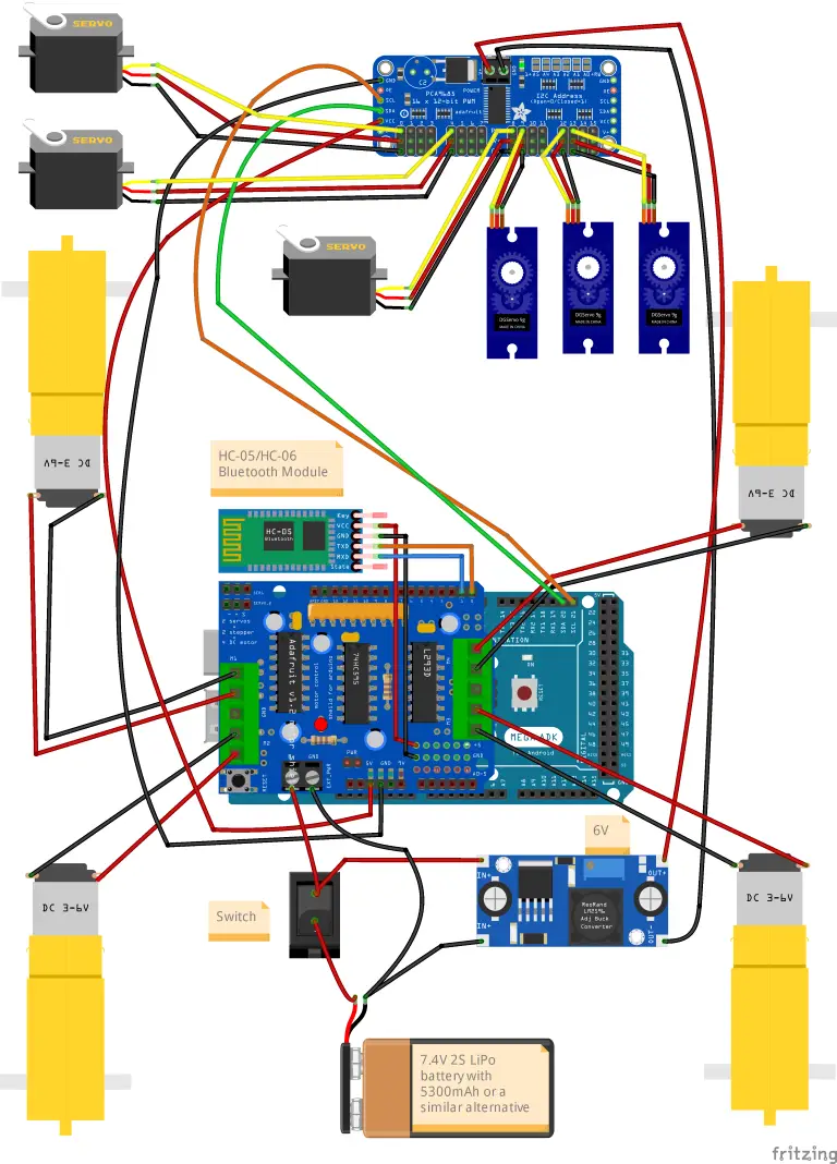
Wiring the components properly is essential for the functionality and safety of this Bluetooth-controlled robot project. The following steps guide you through the connections:
1. Connecting the Motors to the Motor Shield
Attach the left motors to the terminals labeled M1 and M2 on the Adafruit Motor Shield.Attach the right motors to the terminals labeled M3 and M4.
2. Powering the System with a 7.4V 2S LiPo Battery
Use a 7.4V 2S LiPo battery with 5300mAh capacity and an EC3 connector.Solder a compatible EC3 plug to the input of the circuit.Add a switch between the battery and the circuit to easily control power flow.
3. Using the LM2596 DC-DC Step-Down Converter
Connect the battery in parallel to the LM2596 step-down converter.Adjust the potentiometer on the converter to step down the voltage to 6V, which will power the PCA9685 servo driver board.Ensure the output is connected to the VCC and GND terminals on the PCA9685 board.
4. Powering the PCA9685 and Servos
It’s critical to use this independent power source (6V from the LM2596) to avoid overloading the Arduino’s onboard regulator.Connect each servo to the PCA9685 servo driver board, ensuring proper alignment of the signal, VCC, and GND pins.
6. Connecting the HC-05 Bluetooth Module
VCC to 5V on the Arduino Mega.GND to GND on the Arduino Mega.TXD to RX (Pin 0) on the Arduino Mega.RXD to TX (Pin 1) on the Arduino Mega.
6. Connecting the Adafruit Motor Shield to the Arduino
Place the Motor Shield securely onto the Arduino Mega, ensuring all pins are aligned and seated correctly.
7. Testing the Power Distribution
Verify all power connections, ensuring there is no short circuit.Check that the motors, servos, and HC-05 module are receiving the correct voltage as per their requirements.
Following these steps ensures that the robot is wired safely and efficiently, ready for programming and operation.
Step 5: Programming the Mobile Robot Arm for Bluetooth Control
In this step, we program the Arduino to control the robotic arm and the mobile platform via Bluetooth. The code is divided into logical sections for better understanding. Below, each block of code is given:
Step 6: Developing the ArmControl App for Bluetooth Control
The ArmControl App is a custom-built Android application designed to control the Arm platform wirelessly via Bluetooth. This intuitive app allows users to precisely control the robotic arm, save poses, and manage the movement of the mobile platform. Here’s how the app was developed step by step:
Key Features of the App
Bluetooth Connectivity:
The app connects to the HC-05 Bluetooth module attached to the robotic platform.Users can pair their device and establish a connection via the “Select Device” button.

Robotic Arm Control:
Six sliders control the arm’s joints, from the base to the gripper. Each slider sends position data to the corresponding servo motor in real-time.The app ensures smooth and precise movements of the robotic arm.
Mobile Platform Control:
Four directional buttons (Forward, Backward, Left, Right) manage the movement of the rover.A stop button halts all motor actions immediately.
Pose Management:
“Save” button stores the current arm position as a pose.“Play” initiates playback of saved poses, while “Reset” clears all saved configurations.A toggle switch enables or disables looped playback.
Feedback Display:
The app shows the connection status and the number of saved poses, ensuring clarity for the user.
Steps to Build the App
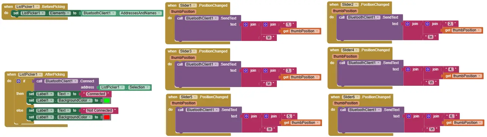
1. Bluetooth Connection Setup
ListPicker Before/After Picking:The app scans for available Bluetooth devices and displays them in a list. Once the user selects a device, the app attempts to connect.On successful connection, the app updates the interface to indicate a “Connected” status.
2. Arm Joint Control with Sliders
Six Sliders for Joint Movement:Each slider corresponds to one of the six servos of the robotic arm.When a slider is adjusted, the app sends the position as a command (e.g., 1,90\n for Servo 1 to move to 90°).This ensures precise manual control over each joint.
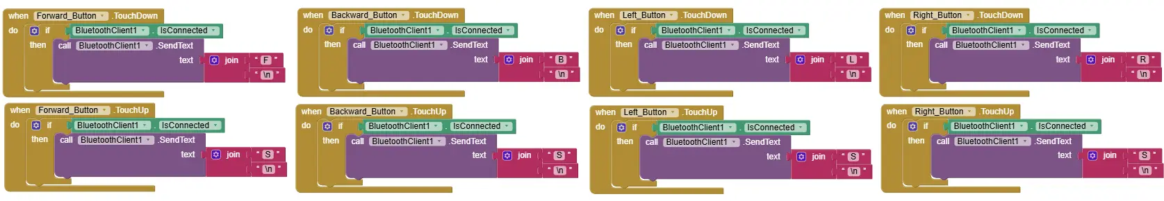
3. Rover Movement Control
Directional Buttons:Each button corresponds to a movement direction for the mobile platform.Example:Forward: Sends F\n to move the rover forward.Backward: Sends B\n to move the rover backward.Left: Sends L\n, and Right: Sends R\n.The Stop button halts all movement with the S\n command.
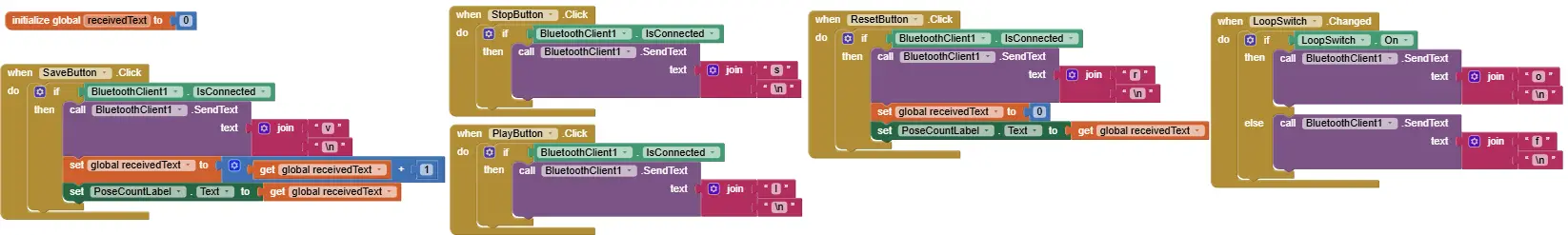
4. Pose Management
Save, Play, Reset, and Loop Playback:Save: Captures the current servo positions and sends v\n to the robot for storage.Play: Starts playback of stored poses with the l\n command.Reset: Clears all saved poses with the r\n command.Loop Playback: A toggle switch sends o\n for enabling loops or f\n to disable them.
5. Real-Time Feedback
The app dynamically updates the number of saved poses and provides visual feedback on Bluetooth connection status.
How It Works
Connecting to the Robot:
Open the app and click “Select Device.”Choose the HC-05 module from the list of available devices.Once connected, the status changes to “Connected.”
Controlling the Robotic Arm:
Use the sliders to move the robotic arm’s joints. Adjustments are sent to the robot in real-time.
Managing Poses:
Save poses with the “Save” button and play them back with “Play.”Enable looping for continuous playback using the toggle switch.
Driving the Rover:
Use directional buttons to move the rover and the Stop button to halt all actions immediately.
Step 7: Final Calibration and Testing
Connecting to the Robot:
Open the app and click “Select Device.”Choose the HC-05 module from the list of available devices.Once connected, the status changes to “Connected.”
Controlling the Robotic Arm:
Use the sliders to move the robotic arm’s joints. Adjustments are sent to the robot in real-time.
Managing Poses:
Save poses with the “Save” button and play them back with “Play.”Enable looping for continuous playback using the toggle switch.
Driving the Rover:
Use directional buttons to move the rover and the Stop button to halt all actions immediately.
Conclusion
The project demonstrates a comprehensive approach to robotics by combining mobility with manipulation, making it ideal for beginners and enthusiasts. The step-by-step guide covered 3D design, assembly, wiring, programming, and app development to achieve a fully functional, Bluetooth-controlled robot. This integration of the robotic arm and mobile platform provides hands-on experience in mechatronics, automation, and software development. In the next project, we plan to equip the Arm with four ultrasonic sensors to enable obstacle avoidance and object detection, allowing the arm to autonomously locate and grasp objects.
#include <Wire.h>
#include <Adafruit_PWMServoDriver.h>
#include <AFMotor.h>

// Constants and definitions
const int numServos = 6; // Number of servos
const int maxConfigurations = 10; // Maximum number of storable poses
const int stepDelay = 10; // Delay between each step to slow down the servo movement
const int stepSize = 1;   // The number of degrees to move per step

// Servo channels on the PCA9685
const int servoChannels[numServos] = {0, 4, 8, 9, 12, 13};

// Storage structures
int savedConfigurations[maxConfigurations][numServos];
int currentServoPositions[numServos] = {375, 375, 375, 375, 375, 375}; // Default positions
int configCount = 0;            // Counter for stored poses
bool isPlaying = false;         // Status indicating if poses are being played
bool loopPlayback = false;      // Status indicating if poses should be played in a loop
bool stopPlaying = false;       // Status indicating if playback should be stopped
int currentPoseIndex = 0;       // Index of the current pose during playback

// Motor instances for the rover
AF_DCMotor motor1(1);
AF_DCMotor motor2(2);
AF_DCMotor motor3(3);
AF_DCMotor motor4(4);

Adafruit_PWMServoDriver pwm = Adafruit_PWMServoDriver();
String input = ""; // Holds incoming Bluetooth data

void setup() {
  Serial.begin(9600); // Serial communication for Bluetooth

  // Initialize motors
  motor1.setSpeed(255);
  motor2.setSpeed(255);
  motor3.setSpeed(255);
  motor4.setSpeed(255);

  // Initialize servo controller
  pwm.begin();
  pwm.setPWMFreq(50); // Set frequency to 50 Hz for servos

  // Initialize servo positions
  for (int i = 0; i < numServos; i++) {
    pwm.setPWM(servoChannels[i], 0, currentServoPositions[i]);
  }

  Serial.println("Bluetooth Robot Controller ready. Waiting for commands...");
}

void loop() {
  // Process incoming commands
  if (Serial.available()) {
    input = Serial.readStringUntil('\n'); // Read data from Bluetooth
    input.trim();

    Serial.println("Received command: " + input);
    processCommand(input);
  }

  // Check if robot arm is playing poses
  if (isPlaying && !stopPlaying) {
    if (loopPlayback) {
      playPosesInLoop();
    } else {
      playNextPose();
    }
  }
}

void processCommand(String command) {
  // If playing, ignore all rover commands
  if (isPlaying) {
    if (command == "s") { // Allow stop playback command
      stopPlayingPoses();
    } else {
      Serial.println("Playback in progress. Ignoring command: " + command);
    }
    return;
  }

  // Control rover movement
  if (command == "F") {
    forward();
  } else if (command == "B") {
    backward();
  } else if (command == "L") {
    turnLeft();
  } else if (command == "R") {
    turnRight();
  } else if (command == "S") {
    stopMotors(); // Stop motors immediately on "S" command

  // Control robotic arm
  } else if (command.startsWith("1,")) {
    processServoCommand(command, 0); // Control Servo 1
  } else if (command.startsWith("2,")) {
    processServoCommand(command, 1); // Control Servo 2
  } else if (command.startsWith("3,")) {
    processServoCommand(command, 2); // Control Servo 3
  } else if (command.startsWith("4,")) {
    processServoCommand(command, 3); // Control Servo 4
  } else if (command.startsWith("5,")) {
    processServoCommand(command, 4); // Control Servo 5
  } else if (command.startsWith("6,")) {
    processServoCommand(command, 5); // Control Servo 6

  // Save, play, reset poses
  } else if (command == "v") {
    saveCurrentPose();
  } else if (command == "l") {
    startPlayingPoses();
  } else if (command == "r") {
    resetPoses();
  } else if (command == "s") {
    stopPlayingPoses();
  } else if (command == "o") {
    loopPlayback = true;
    Serial.println("Loop playback enabled.");
  } else if (command == "f") {
    loopPlayback = false;
    Serial.println("Loop playback disabled.");
  } else {
    Serial.println("Unknown command: " + command);
  }
}

void processServoCommand(String command, int servoIndex) {
  int commaIndex = command.indexOf(',');
  if (commaIndex > 0) {
    int position = command.substring(commaIndex + 1).toInt();
    int pwmValue = map(position, 0, 180, 150, 600);
    moveToPositionSmoothly(servoIndex, pwmValue);
  }
}

// Rover motor control
void forward() {
  motor1.run(FORWARD);
  motor2.run(FORWARD);
  motor3.run(FORWARD);
  motor4.run(FORWARD);
  Serial.println("Moving forward");
}

void backward() {
  motor1.run(BACKWARD);
  motor2.run(BACKWARD);
  motor3.run(BACKWARD);
  motor4.run(BACKWARD);
  Serial.println("Moving backward");
}

void turnLeft() {
  motor1.run(BACKWARD);
  motor2.run(BACKWARD);
  motor3.run(FORWARD);
  motor4.run(FORWARD);
  Serial.println("Turning left");
}

void turnRight() {
  motor1.run(FORWARD);
  motor2.run(FORWARD);
  motor3.run(BACKWARD);
  motor4.run(BACKWARD);
  Serial.println("Turning right");
}

void stopMotors() {
  motor1.run(RELEASE);
  motor2.run(RELEASE);
  motor3.run(RELEASE);
  motor4.run(RELEASE);
  Serial.println("Motors stopped");
}

// Arm servo control
void moveToPositionSmoothly(int servoIndex, int targetPwmValue) {
  int currentPwmValue = currentServoPositions[servoIndex];
  if (targetPwmValue > currentPwmValue) {
    for (int pos = currentPwmValue; pos <= targetPwmValue; pos += stepSize) {
      pwm.setPWM(servoChannels[servoIndex], 0, pos);
      delay(stepDelay);
    }
  } else {
    for (int pos = currentPwmValue; pos >= targetPwmValue; pos -= stepSize) {
      pwm.setPWM(servoChannels[servoIndex], 0, pos);
      delay(stepDelay);
    }
  }
  currentServoPositions[servoIndex] = targetPwmValue;
  Serial.println("Servo " + String(servoIndex + 1) + " set to position: " + String(targetPwmValue));
}

// Pose handling for the arm
void saveCurrentPose() {
  if (configCount < maxConfigurations) {
    for (int i = 0; i < numServos; i++) {
      savedConfigurations[configCount][i] = currentServoPositions[i];
    }
    configCount++;
    Serial.println("Pose saved. Total poses: " + String(configCount));
  } else {
    Serial.println("Memory full. Cannot save pose.");
  }
}

void startPlayingPoses() {
  if (configCount > 0) {
    stopMotors(); // Ensure rover is stopped during playback
    isPlaying = true;
    stopPlaying = false;
    currentPoseIndex = 0;
    Serial.println("Starting pose playback");
  } else {
    Serial.println("No poses saved");
  }
}

void playNextPose() {
  if (currentPoseIndex < configCount) {
    for (int i = 0; i < numServos; i++) {
      moveToPositionSmoothly(i, savedConfigurations[currentPoseIndex][i]);
    }
    delay(1000);
    currentPoseIndex++;
  } else {
    isPlaying = false;
    Serial.println("Pose playback finished");
  }
}

void playPosesInLoop() {
  for (int i = 0; i < configCount; i++) {
    if (stopPlaying) break; // Immediate stop on command
    for (int j = 0; j < numServos; j++) {
      moveToPositionSmoothly(j, savedConfigurations[i][j]);
    }
    delay(1000);
  }
}

void stopPlayingPoses() {
  stopPlaying = true;
  isPlaying = false;
  Serial.println("Pose playback stopped");
}

void resetPoses() {
  configCount = 0;
  isPlaying = false;
  loopPlayback = false;
  currentPoseIndex = 0;
  Serial.println("All poses reset");
}


