
In this tutorial we will learn how to make an Arduino Robot Arm which can be wirelessly controlled and programmed using a custom-build Android application. I will show you the entire process of building it, starting from designing and 3D printing the robot parts, connecting the electronic components and programming the Arduino, to developing our own Android application for controlling the Robot Arm.
Step 1: Description
Overview
Using the sliders in the app we can manually control the movement of each servo or axis of the robot arm. Also using the “Save” button we can record each position or step and then the robot arm can automatically run and repeat these steps. With the same button we can pause the automatic operation as well as reset or delete all steps so that we can record new ones.
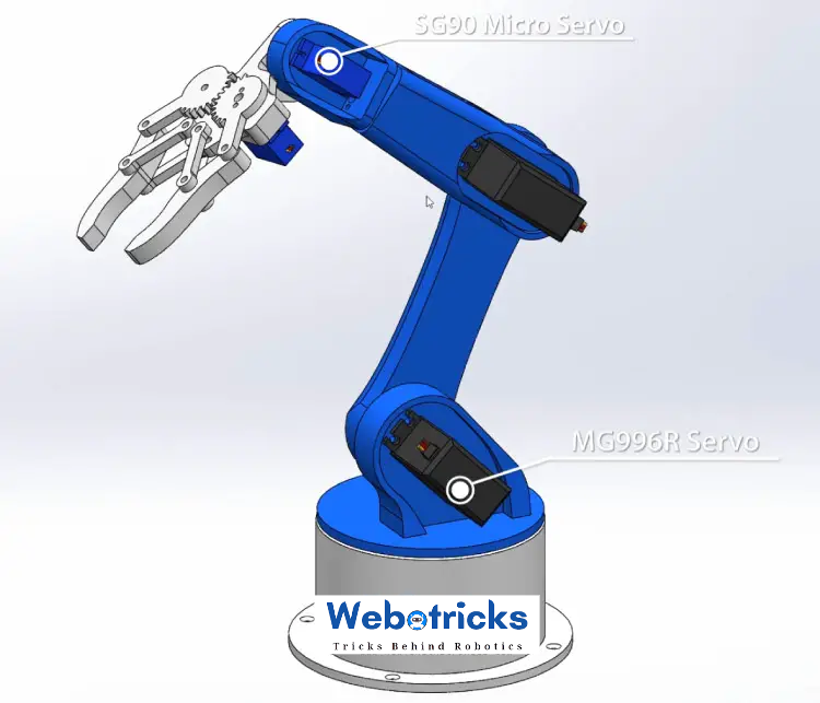
Arduino Robot Arm 3D Model
To begin with, I designed the Robot Arm using Solidworks 3D modeling software. The arm has 5 degrees of freedom.
Step 2:

For the first 3 axis, the waist, the shoulder and the elbow, I used the MG996R servos, and for the other 2 axis, the wrist roll and wrist pitch, as well as the gripper I used the smaller SG90 micro servos.
You can get this 3D model, as well as the STL files for 3D Printing from Cults3D.
Step 3:
3D Printing the Robot Arm
Using my new 3D Printer, Creality CR-10, I 3D printed all of the parts for the Arduino robot arm.
I had all of the parts for the Arduino Robot Arm ready in just several hours.
Step 4:
Assembling the Robot Arm
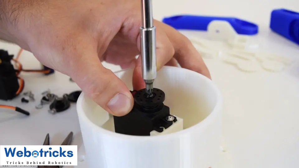
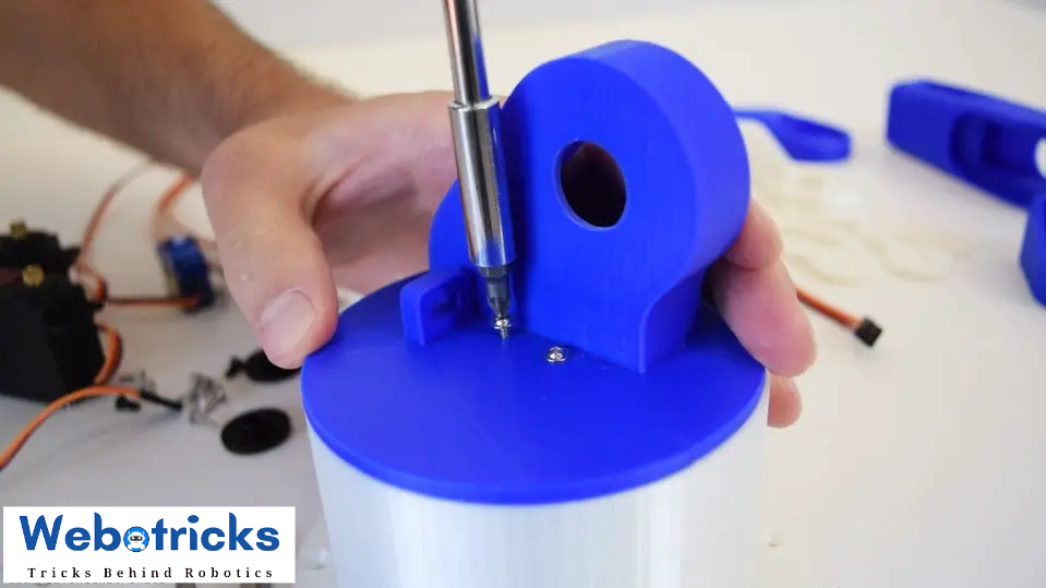
Ok, so at this point we are ready to assemble the robot arm. I started with the base on which I attached the first servo motor using the screws included in its package. Then on the output shaft of the servo I secured a round horn a bolt.
Step 5:


And on top of it I placed the upper part and secured it using two screws.
Here again first goes servo, then the round horn onto the next part, and then they are secured to each other using the bolt on the output shaft.
We can notice here that at the shoulder axis it is good idea to include some kind of spring or in my case I used a rubber band to give some help to the servo because this servo carries the whole weight of the rest of the arm as well as the payload.
In similar way I continued to assemble the rest of the robot arm. As for the gripper mechanism I used some 4 millimeters bolts and nuts to assembly it.
Finally I attached the gripper mechanism onto the last servo and the Arduino robot arm was completed.
Arduino Robot Arm Circuit Diagram
The next stage is connecting the electronics. The circuit diagram of this project is actually quite simple. We just need an Arduino board and a HC-05 Bluetooth module for communication with the smartphone. The control pins of the six servo motors are connected to six digital pins of the Arduino board.
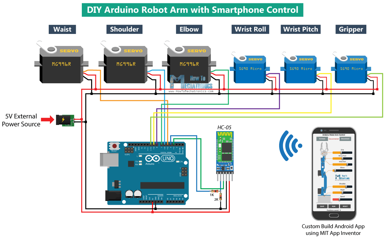
For powering the servos we need 5V, but this must come from an external power source because the Arduino is not able to handle the amount of current that all of them can draw. The power source must be able to handle at least 2A of current. So once we have connected everything together we can move on to programing the Arduino and make the Android app.
You can get the components needed for this example from the links below:
MG996R Servo Motor::https://www.webotricks.com/products?name=Servo+Motor&global_search_input=1&data_from=search&page=1SG90 Micro Servo Motor ……..…….https://www.webotricks.com/products?name=Servo+Motor&global_search_input=1&data_from=search&page=1HC-05 Bluetooth Module ………………https://www.webotricks.com/products?name=HC-05+Bluetooth+&global_search_input=1&data_from=search&page=1Arduino Board ……………………………………. https://www.webotricks.com/product/arduino-uno-r3-dip-compatible-development-board-7iygMS5V 2A DC Power Supply ……………https://www.webotricks.com/products?name=5V+2A+DC+Power+Supply&global_search_input=1&data_from=search&page=1Disclosure: These are affiliate links. As an Amazon Associate I earn from qualifying purchases.
Arduino Robot Arm Code
As the code is a bit longer, for better understanding, I will post the source code of the program in sections with description for each section. And at the end of this article I will post the complete source code.
So first we need to include the SoftwareSerial library for the serial communication of the Bluetooth module as well as the servo library. Both of these libraries are included with the Arduino IDE so you don’t have to install them externally. Then we need to define the six servos, the HC-05 Bluetooth module and some variables for storing the current and previous position of the servos, as well as arrays for storing the positions or the steps for the automatic mode.


