

Just a few weeks ago, I got a development board from DFRobot. The board is based on ESP32-S3 SoC and it has camera and other audio interfaces such as Microphone and digital amplifier. I was thinking about making some camera-based device that can be useful gadget for people who like technology. So, then it came to create a peephole camera for homes. Peephole cameras can be fixed near home door so anyone who come to home when the owner is not there can keep a message for the owner. The message can then be used to get the information.
DFRobot ESP32s3 AI camera
This is a device with many interesting features. This development board has 3 MP OV3660 camera. It has various other interesting interfaces to make this kind of project a reality.
The following features makes it possible to create a Peephole camera.
- > 3 MP OV3660 camera with IR LEDs for night vision
- > ESP32-S3 SoC with WiFi and Bluetooth interface
- > LTR-308 Light intensity sensor
- > I2S MEMS microphone
- > SD card slot to store image, audio recordings
- > Speaker with amplifier for playing the audio
- > Upto 3.7-15V DC power supply option
The board has WiFi/BLE interface that can be used for transferring files between the user's PC/Laptop or cell phone. The camera can be used to save images and the microphone to save audio recordings. The speaker can be used to play some example audio as well.

The Goal
As I am working on this project using DFRobot ESP32-s3 AI camera, one question is always there. How should the final device look like? or What features it has? To answer this question, I have the following goals, not all of them must be fulfilled.
The device should be able to capture the camera image. It should also be able to record audio from the single microphone on the device. It should then be able to store the image and the microphone audio in the connected SD card on the SPI interface. The SPI filesystem on the device should be available on the FTP server side so that clients can download stored photos and recordings. This will inform them who came to meet them and get the image and audio message they have left for them when they were not available.
Apart from these important features (must have) that I have just mentioned above, I also want that the light intensity sensor can work as a switch to trigger events. The digital audio speaker connected through I2S amplifier should also be able to play some pre-stored audio files to guide the new user. Let's dive into the detail of the project itself to know whether it would be possible or not.
Software Requirements
For the software part, I did some research. The support of features that I want for my device are of the following libraries in the top to least priority order.
- OV-3660 camera API support
- Microphone I2S support
- SD-Card SPI interface support
- FTP Server support
- I2S speaker support
- I2C sensor support
Not all of these features could be possible with every software supported for ESP32-s3 device. I had to make one out of three choices from Arduino, ESP-IDF or Micropython.
For the software part, I decided to use ESP-IDF. There were some challenging questions in the beginning but after some research, I decided to finally go for it. I also looked at Micropython support because Python is fast and we can create something interesting easily. Also, there is micro python port for ESP32-s3. But proper support and settings for OV3660 camera was missing (Unless we create custom firmware and flash it to the ESP32 it seemed impossible to me). Though there was support for FTP server in Micropython. Hence, I decided to use ESP-IDF as it has support for all of the required features that I have mentioned above. Also, it can manage different tasks efficiently with priority, interrupt and data sharing/locking mechanisms.
One cannot write all the software components by themselves. So, the software re-use should be encouraged. For example, I do not have much knowledge about FTP and computer networking protocols so much that I can implement them on ESP32 all by myself. It also takes much time. Hence, I have used some open-source libraries to make it happen. Same goes for camera interface where Espressif itself provides API/component for camera interface.
For including these API/components into our project, we need to make required changes to the CMakeFile.txt and idf_component.yml files so that we can add required header files and other features to the project. If we add more .C/.h code into the project, then also we need to mention that inside Cmakefile. Mastering this settings would make working with project very easy and efficient. There is also menuconfig/kconfig settings that are used for settings related to project variables, pins, GPIOs, etc. This must be taken care of. Otherwise, errors could arrise at any time in the project build.
Aso one thing to note here is that ESP32 does not explicitly mention some settings but they are required for the correct working of your project. For example, nvs_flash must be enabled in the project main() function for storing/accessing data and other variables. I will list some of these requirements for this project right up front.
- > Enable nvs_flash interface in CMake and inside the main() function (This is required)
- > Enable PSRAM for camera support to store temporary data buffers (Camera interface will not work without this)
- > Enable external flash mode like Quad or Octa interface (wrong mode means error)
Implementing FTP server on ESP32
For implementing FTP server on ESP32 with ESP-IDF, there were two options. One was the FTP component available online by nopnop2002. Another option was to use espp FTP component available online. Both of these options are possible. But the espp has C++ based library and that would create extra efforts to mix C and C++ code in one project. Also, most of my peripherals and library API are C coding standard. And using C++ for FTP support and adapting other C based code would be time consuming. Hence, I tried the simple FTP component library from nopnop2002 mentioned above. The simple code worked as expected and that was it. This is what I wanted to have for my project.
For FTP server implementation, we will need WiFi to be working and connected to our local internet. The first thing that FTP server implementation does is to get the ntp time from ntp server. So that we know when exactly the photo and the audio was captured and keep track of time thought our application.
For implementing the sever on ESP32, I had a look at the example on Github. In this there is a .C source file to start the FTP task. This source file must be included during compilation. So I have added the following lines in my CMakeFile.txt.
idf_component_register(SRCS "example_main.c" "ftp.c" INCLUDE_DIRS ".")
This will help me to create an FTP task in my main() function. Also, as you can see in the following code, I have initialized WiFi as a station mode. In the station mode, I can create SNTP tasks to get the time and then start the FTP server task. The ESP32 can get the accurate time and date information from the internet if correct time zone is set.
void app_main(void)
{
ESP_LOGI(TAG, "ESP_WIFI_MODE_STA");
wifi_init_sta();
if (ret != ESP_OK) {
ESP_LOGE(TAG, "Failed to initialize WiFi: %s", esp_err_to_name(ret));
return;
}
// Initialize mDNS
initialise_mdns();
// Obtain local IP address
esp_netif_ip_info_t ip_info;
ESP_ERROR_CHECK(esp_netif_get_ip_info(esp_netif_get_handle_from_ifkey("WIFI_STA_DEF"), &ip_info));
// Print the local IP address
ESP_LOGI(TAG, "IP Address : " IPSTR, IP2STR(&ip_info.ip));
ESP_LOGI(TAG, "Subnet mask: " IPSTR, IP2STR(&ip_info.netmask));
ESP_LOGI(TAG, "Gateway : " IPSTR, IP2STR(&ip_info.gw));
// Obtain time over NTP
ESP_LOGI(TAG, "Getting time over NTP.");
ESP_ERROR_CHECK(obtain_time());
// Show current date & time
time_t now;
struct tm timeinfo;
char strftime_buf[64];
time(&now);
now = now + (CONFIG_LOCAL_TIMEZONE*60*60) + (30*60); // Adjust for timezone and 30 minutes
localtime_r(&now, &timeinfo);
strftime(strftime_buf, sizeof(strftime_buf), "%c", &timeinfo);
ESP_LOGI(TAG, "The local date/time is: %s", strftime_buf);
ESP_LOGW(TAG, "This server manages file timestamps in GMT.");
// Create FTP server task
xEventTask = xEventGroupCreate();
xTaskCreate(ftp_task, "FTP", 1024*6, NULL, 2, NULL);
xEventGroupWaitBits( xEventTask,
FTP_TASK_FINISH_BIT,
pdTRUE,
pdFALSE,
portMAX_DELAY);
ESP_LOGE(TAG, "ftp_task finish");
After the FTP server is initialized, we can use clients like Winscp on PC to connect to the ESP32 and start transfer of files. You can also change the default password and username if you want. It is also possible to set the static IP for your ESP32. This will help a lot in your development. One can also setup Raspberry-Pi to sync the folder and files between the ESP32 and Raspberry Pi. This will always sync the files between your device and Raspberry Pi and make the transfer of these files faster at latter point of time. I have not done Raspberry Pi setup for this project.

Light intensity sensor support
I wanted to have support for light intensity sensor on this board. The data from light intensity sensor could be used for many things like turn on the IR LEDs during night hours or it can also work as a presence detector to take photos and audio from camera and microphone respectively.
I have already done the task of creating software component for this sensor and published the blog on element14. You can find the component online on github and the documentation for how it works is also there. I will use this component in my project to get the light intensity data and trigger other events such as picture from camera and microphone recording. I will store these data in the SD card.
Camera Sensor support
Camera sensor support is absolutely mandatory for this project. The project is nothing without it. But quite luckily the IDF framework provides camera interface APIs that can be used for support for camera. Be it on MIPI interface for ESP32-P4 or DVP interface as in this case for ESP32-S3 and various other ESP32 camera boards. Most sensors from Omnivision of OV series camera are supported. i.e. OV2629, OV3660, etc.
For enabling the camera support, you need to first enable the PSRAM support from the menuconfig. Without that camera API and initialization will not work. It will through an error at the run time.
The following is just an example code to include the camera support in your code. It includes the required header files, then it defines some pins of the camera and define the camera_config_t device structure required to initialize the camera. The code and the GPIO pins are adapted to the DFRobot development board that I have.
(This code as it is will not work, one needs to enable other peripherals and adapt the code to their requirement. For example, the I2C peripheral, nvs flash enable should be done as well.)
The following is the camera settings for DFRobot camera.
#include "esp_camera.h"
// DFRobot ESP32-S3 AI-CAM Pin configuration
#define CAM_PIN_PWDN -1 //power down is not used
#define CAM_PIN_RESET -1 //software reset will be performed
#define CAM_PIN_XCLK 5
#define CAM_PIN_SIOD 8
#define CAM_PIN_SIOC 9
#define CAM_PIN_D7 4
#define CAM_PIN_D6 6
#define CAM_PIN_D5 7
#define CAM_PIN_D4 14
#define CAM_PIN_D3 17
#define CAM_PIN_D2 21
#define CAM_PIN_D1 18
#define CAM_PIN_D0 16
#define CAM_PIN_VSYNC 1
#define CAM_PIN_HREF 2
#define CAM_PIN_PCLK 15
static camera_config_t camera_config = {
.pin_pwdn = CAM_PIN_PWDN,
.pin_reset = CAM_PIN_RESET,
.pin_xclk = CAM_PIN_XCLK,
.pin_sccb_sda = CAM_PIN_SIOD,
.pin_sccb_scl = CAM_PIN_SIOC,
.pin_d7 = CAM_PIN_D7,
.pin_d6 = CAM_PIN_D6,
.pin_d5 = CAM_PIN_D5,
.pin_d4 = CAM_PIN_D4,
.pin_d3 = CAM_PIN_D3,
.pin_d2 = CAM_PIN_D2,
.pin_d1 = CAM_PIN_D1,
.pin_d0 = CAM_PIN_D0,
.pin_vsync = CAM_PIN_VSYNC,
.pin_href = CAM_PIN_HREF,
.pin_pclk = CAM_PIN_PCLK,
.xclk_freq_hz = 20000000,
.ledc_timer = LEDC_TIMER_0,
.ledc_channel = LEDC_CHANNEL_0,
.pixel_format = PIXFORMAT_JPEG,//YUV422,GRAYSCALE,RGB565,JPEG
.frame_size = FRAMESIZE_UXGA,//QQVGA-UXGA
.jpeg_quality = 5, //0-63, for OV series camera sensors, lower number means higher quality
.fb_count = 2,
.grab_mode = CAMERA_GRAB_WHEN_EMPTY//CAMERA_GRAB_LATEST. Sets when buffers should be filled
};
void app_main(void)
{
// Initialize camera
esp_err_t err = esp_camera_init(&camera_config);
if (err != ESP_OK) {
printf("Camera init failed with error 0x%x", err);
return;
}
camera_fb_t *pic = esp_camera_fb_get();
}
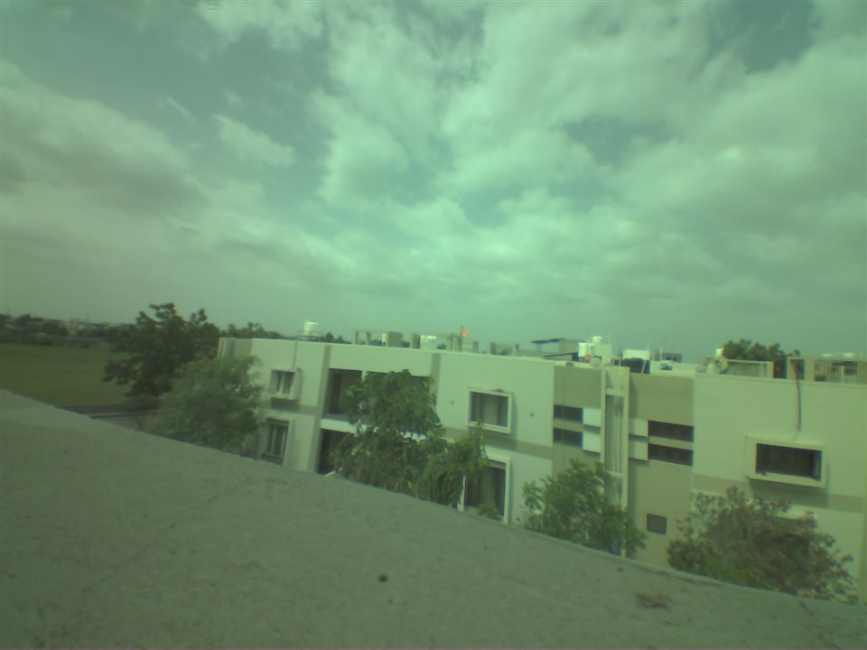
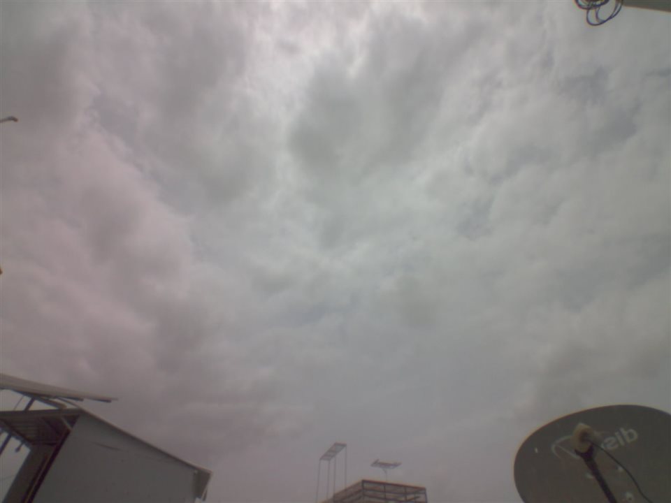
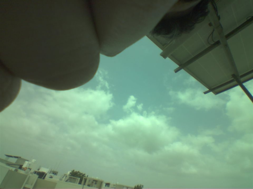
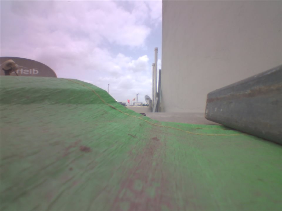
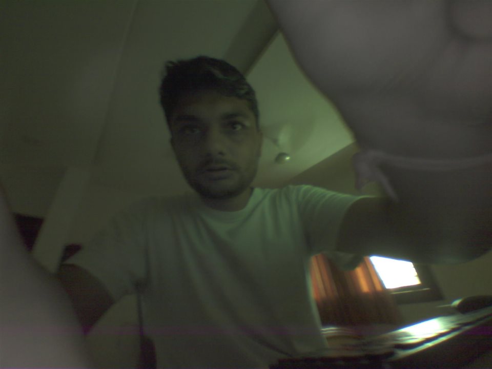
I have captured some demo images both indoor and outdoor to have an idea how the images are. The images are very small size and clear enough to see a person or an object.
The size range of image is typically between ~ 100 to 300 Kb. That is good for IoT applications like this.

SD-Card Support
On this development board, the SD-Card is connected over single line SPI interface. There is Quad SPI interface for SD-card as well for faster data transfer, but this is not supported on this device. Make sure to use proper settings in your project if you want to use SD-Card.
First, you need to include SD-Card support in your project CmakeFile.txt. For that, add the following lines.
PRIV_REQUIRES fatfs sd_card
#include "esp_vfs_fat.h"
#include "sdmmc_cmd.h"
#include "driver/sdmmc_host.h"
#include "sd_test_io.h"
//SD-Card configuration
#define MOUNT_POINT "/root"
#define PIN_NUM_MISO 13
#define PIN_NUM_MOSI 11
#define PIN_NUM_CLK 12
#define PIN_NUM_CS 10
void app_main() {
esp_vfs_fat_sdmmc_mount_config_t mount_config = {
.format_if_mount_failed = false,
.max_files = 5,
.allocation_unit_size = 16 * 1024
};
sdmmc_card_t *card;
const char mount_point[] = MOUNT_POINT;
ESP_LOGI(TAG, "Initializing SD card");
sdmmc_host_t host = SDSPI_HOST_DEFAULT();
host.unaligned_multi_block_rw_max_chunk_size = 8;
spi_bus_config_t bus_cfg = {
.mosi_io_num = PIN_NUM_MOSI,
.miso_io_num = PIN_NUM_MISO,
.sclk_io_num = PIN_NUM_CLK,
.quadwp_io_num = -1,
.quadhd_io_num = -1,
.max_transfer_sz = 4000,
};
ret = spi_bus_initialize(host.slot, &bus_cfg, SDSPI_DEFAULT_DMA);
if (ret != ESP_OK) {
ESP_LOGE(TAG, "Failed to initialize bus.");
return;
}
// This initializes the slot without card detect (CD) and write protect (WP) signals.
// Modify slot_config.gpio_cd and slot_config.gpio_wp if your board has these signals.
sdspi_device_config_t slot_config = SDSPI_DEVICE_CONFIG_DEFAULT();
slot_config.gpio_cs = PIN_NUM_CS;
slot_config.host_id = host.slot;
ESP_LOGI(TAG, "Mounting filesystem");
ret = esp_vfs_fat_sdspi_mount(mount_point, &host, &slot_config, &mount_config, &card);
if (ret != ESP_OK) {
if (ret == ESP_FAIL) {
ESP_LOGE(TAG, "Failed to mount filesystem. "
"If you want the card to be formatted, set the CONFIG_EXAMPLE_FORMAT_IF_MOUNT_FAILED menuconfig option.");
} else {
ESP_LOGE(TAG, "Failed to initialize the card (%s). "
"Make sure SD card lines have pull-up resistors in place.", esp_err_to_name(ret));
#ifdef CONFIG_EXAMPLE_DEBUG_PIN_CONNECTIONS
check_sd_card_pins(&config, pin_count);
#endif
}
return;
}
ESP_LOGI(TAG, "Filesystem mounted");
// Card has been initialized, print its properties
sdmmc_card_print_info(stdout, card);
}
Once SD-card supports is there, you can format your SD card in FATFS files system and insert the card into the slot. Then you will be able to store/access image and audio files in the SD card.
MIC interface
There is an I2S Microphone on this device. The first thing that I did to know whether this works as expected is I tried one of the samples that Espressif provides. (after making the required pin settings). I noted that I can record some audio files in .wav format into the SD-Card. This was enough for me to integrate Microphone into my project.
After the files with right naming and possibly the timestamp is recorded one can get the data easily using FTP client.
For enabling the I2S Microphone support one needs to add the component configuration in CMakeLists.txt file. This will let us add the header files for I2S.
PRIV_REQUIRES esp_driver_i2s
The next part is to add the actual I2S related code. The following code enables the I2S functionality into your projects. As you can notice that I amusing MONO(single channel I2S configutation). I am using sample rate of 44100. I am also adding the pins for I2S clock and data as per the board that I have. I have set the bit width to 16-bits.
#include "driver/i2s_pdm.h"
#include "format_wav.h"
// I2S configuration
#define NUM_CHANNELS (1) // For mono recording only!
#define SAMPLE_SIZE (16 * 1024)
#define BYTE_RATE (44100 * (16 / 8)) * NUM_CHANNELS
i2s_chan_handle_t rx_handle = NULL;
static int16_t i2s_readraw_buff[SAMPLE_SIZE];
size_t bytes_read;
const int WAVE_HEADER_SIZE = 44;
void init_microphone(void)
{
#if SOC_I2S_SUPPORTS_PDM2PCM
ESP_LOGI(TAG, "Receive PDM microphone data in PCM format");
#else
ESP_LOGI(TAG, "Receive PDM microphone data in raw PDM format");
#endif // SOC_I2S_SUPPORTS_PDM2PCM
i2s_chan_config_t chan_cfg = I2S_CHANNEL_DEFAULT_CONFIG(I2S_NUM_AUTO, I2S_ROLE_MASTER);
ESP_ERROR_CHECK(i2s_new_channel(&chan_cfg, NULL, &rx_handle));
i2s_pdm_rx_config_t pdm_rx_cfg = {
.clk_cfg = I2S_PDM_RX_CLK_DEFAULT_CONFIG(44100),
/* The default mono slot is the left slot (whose 'select pin' of the PDM microphone is pulled down) */
#if SOC_I2S_SUPPORTS_PDM2PCM
.slot_cfg = I2S_PDM_RX_SLOT_PCM_FMT_DEFAULT_CONFIG(I2S_DATA_BIT_WIDTH_16BIT, I2S_SLOT_MODE_MONO),
#else
.slot_cfg = I2S_PDM_RX_SLOT_RAW_FMT_DEFAULT_CONFIG(I2S_DATA_BIT_WIDTH_16BIT, I2S_SLOT_MODE_MONO),
#endif
.gpio_cfg = {
.clk = 38,
.din = 39,
.invert_flags = {
.clk_inv = false,
},
},
};
ESP_ERROR_CHECK(i2s_channel_init_pdm_rx_mode(rx_handle, &pdm_rx_cfg));
ESP_ERROR_CHECK(i2s_channel_enable(rx_handle));
}
void record_wav(uint32_t rec_time, uint8_t pic_num)
{
int flash_wr_size = 0;
ESP_LOGI(TAG, "Opening file");
uint32_t flash_rec_time = BYTE_RATE * rec_time;
const wav_header_t wav_header =
WAV_HEADER_PCM_DEFAULT(flash_rec_time, 16, 44100, 1);
// First check if file exists before creating a new file.
struct stat st;
if (stat(MOUNT_POINT"/record.wav", &st) == 0) {
// Delete it if it exists
unlink(MOUNT_POINT"/record.wav");
}
// Create new WAV file
char audio_name[20];
sprintf(audio_name, MOUNT_POINT"/audio_%d.wav", pic_num++);
FILE *f = fopen(audio_name, "a");
if (f == NULL) {
ESP_LOGE(TAG, "Failed to open audio file for writing");
return;
}
// Write the header to the WAV file
fwrite(&wav_header, sizeof(wav_header), 1, f);
// Start recording
while (flash_wr_size < flash_rec_time) {
// Read the RAW samples from the microphone
if (i2s_channel_read(rx_handle, (char *)i2s_readraw_buff, SAMPLE_SIZE, &bytes_read, 1000) == ESP_OK) {
//printf("[0] %d [1] %d [2] %d [3]%d ...\n", i2s_readraw_buff[0], i2s_readraw_buff[1], i2s_readraw_buff[2], i2s_readraw_buff[3]);
// Write the samples to the WAV file
fwrite(i2s_readraw_buff, bytes_read, 1, f);
flash_wr_size += bytes_read;
} else {
printf("Read Failed!\n");
}
}
ESP_LOGI(TAG, "Recording done!");
fclose(f);
ESP_LOGI(TAG, "File written on SDCard");
}
Once you get the Mic working, you can try different settings like changing your bit width, sample rate, number of channels and use that to get better audio quality.
Digital Speaker interface
On this device there is MAX98357A I2S digital audio amplifier and speaker. As the ESP32s3 has two I2S peripherals I can connect one of them to the Microphone and another one to the digital amplifier and the speaker interface. I can then play the audio from the SD card and guide the user accordingly. That would be an interesting addition to this device.
First, I tried a simple code to interface I2S amplifier. The code to create a simple sine wave like tone worked fine. The next part is to play some sample audio files.
#define I2S_NUM I2S_NUM_0
#define I2S_BCLK_PIN 45
#define I2S_WS_PIN 46
#define I2S_DO_PIN 42
#define I2S_DI_PIN -1
#define SAMPLE_RATE 44100
#define SAMPLE_BITS I2S_BITS_PER_SAMPLE_16BIT
#define DMA_BUF_COUNT 4
#define DMA_BUF_LEN 1024
static esp_err_t init_speaker(void) {
i2s_chan_config_t chan_cfg = I2S_CHANNEL_DEFAULT_CONFIG(I2S_NUM_AUTO, I2S_ROLE_MASTER);
chan_cfg.auto_clear = true;
/* Allocate a new TX channel and get the handle of this channel */
ESP_ERROR_CHECK(i2s_new_channel(&chan_cfg, &tx_handle, NULL));
i2s_std_config_t std_cfg = {
.clk_cfg = I2S_STD_CLK_DEFAULT_CONFIG(SAMPLE_RATE),
.slot_cfg = I2S_STD_PHILIPS_SLOT_DEFAULT_CONFIG(I2S_DATA_BIT_WIDTH_16BIT, I2S_SLOT_MODE_STEREO),
.gpio_cfg = {
.mclk = -1,
.bclk = I2S_BCLK_PIN,
.ws = I2S_WS_PIN,
.dout = I2S_DO_PIN,
.din = I2S_DI_PIN,
.invert_flags = {
.mclk_inv = false,
.bclk_inv = false,
.ws_inv = false,
},
},
};
ESP_ERROR_CHECK(i2s_channel_init_std_mode(tx_handle, &std_cfg));
//ESP_ERROR_CHECK(i2s_channel_init_std_mode(rx_handle, &std_cfg));
ESP_ERROR_CHECK(i2s_channel_enable(tx_handle));
return ESP_OK;
}
After that, I can add the files that I want to play in the Sd-Card and play it to guide the user. So that user can take photos efficiently and record their audio message.
Once both the Speaker and Microphone are setup, we can tune the different I2S settings to get better audio quality. This should be an iterative process.
Working Demo
In the working demo you can see the project and it's file structure. Also, how different files and functions are organized.
From command line, I can create ESP-IDF environment and build the project. I can then flash the device with right firmware. After the device is flashed it will obtain it's local IP address.
Once the IP is obtained, it will get the sntp time from server based on time zone we have set.
After that the device will keep monitoring Lux data and as soon as we place finger near Lux sensor, it will trigger photo capture and audio recording for 10 seconds. If you want more recordings, you can follow the same procedure again.
Peephole IP- camera for home. - element14 Community
Conclusion
It was intense fun to work on this project. During the making of project I learned so many new things be it on short note. The device that I have showcased in this project could find its way at different places be it inside home or at office. There were some challenging things that I also had to deal with. I will mention all these things in this paragraph.
For the testing part, I have run the device for some hours and it works fine. Sometimes I noticed that I used to get old picture. Hence if I take the picture again, I will get the picture that I clicked previously. This had something to do with camera settings in my code, and I changed the code. Now, I am getting the latest picture with the following line.
.grab_mode = CAMERA_GRAB_LATEST
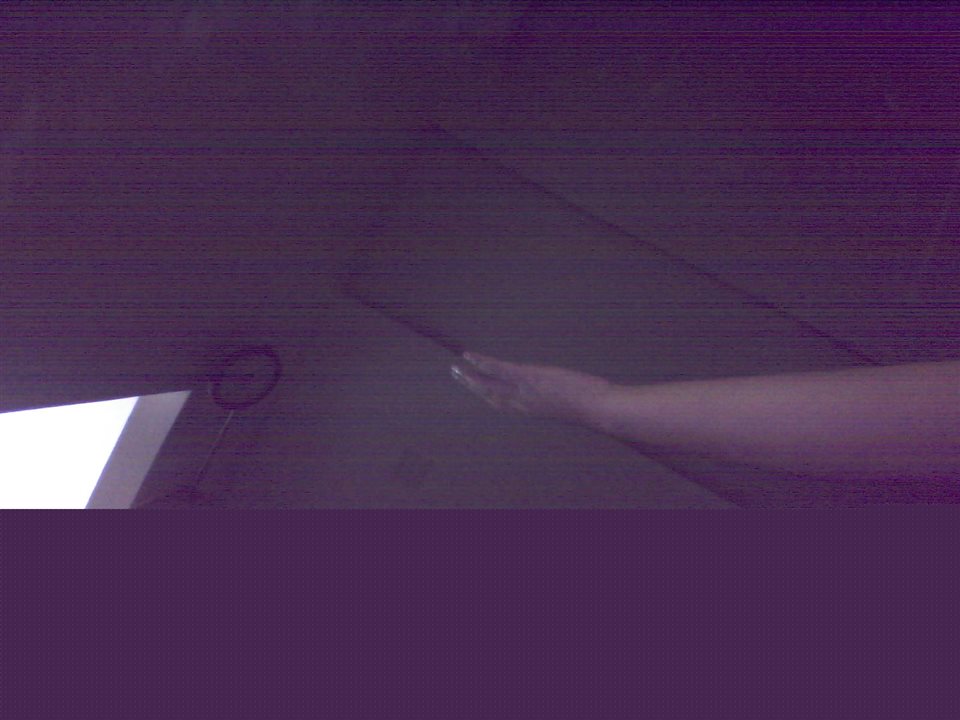
Another issue that I have found is that the pictures are sometimes distorted. This might be in the low light situations or when I try to take picture after a really long time. Here is an example image where the picture is not captured as it should be. It could be due to dark environment, but I have kept the IR LEDs always on. As there is only 4 of them, this is a hardware limitation. If you plan to create something like this device, make sure to add more IR LEDs to capture images also in the dark.
I can use FTP client on my PC and phone to access the ESP32 device. Given the condition that I use only one device at a time. I can download the photos and audio files easily.
The audio files are not that loud. But they are easy to understand. With some kind of setting of the I2S parameter and also signal processing techniques, one may be able to improve the audio quality, but it is not must.
In the future when deploying this device in my home, I would like to add more IR LEDs and also add button for capturing the image and audio message.
Reference and links
DFRobot ESP32-S3 camera module purchase link: ESP32s3 AI camera module
FTP server component for ESP32-s3 FTP Server ESP32-s3
Source files for project : 5466.Project_14.zip