

A 3D printable, MEMs based microphone is proposed in this project. The microphone is laboratory grade, IEPE powered, and less than $30.
Introduction
Acousticians and acoustical engineers often rely on laboratory grade measurement microphones to acquire physical signals during experiments. Typical condenser microphones from companies such as PCB PIEZOTRONICS could run a bill of over $1000 USD for a free-field microphone. The quality of such microphones is superb, but there are alternatives available to the hobbyist and enthusiast which will get you comparable performance for a fraction of the cost. Here, a MEMs based design is explored with the ultimate goal of having a similar noise floor, frequency response, flatness, and sensitivity in the audio band of 20Hz to 20kHz.
Electrical Design
The electronics is split into two boards for the prototype. Ultimately, this should be done with a rigid-flex design to aid in the assembly of the microphones. However, two boards with point-to-point wiring is fine for the prototype and proof of concept. The first board is the MEMs carrier board. Four MEMs elements are mounted on a circular PCB with small through-hole pads scattered around for the necessary power and signal connections.
The second board is the Motherboard or the preamplifier. This contains the inputs and signal conditioning for the MEMs outputs, as well as the IEPE conversion and output modulation - all done with adjustable Zener diodes.

Figure 001: Schematic print of the motherboard/preamplifier board. The jumpers are simple through-hole pads that will accept the wire connections for the BNC interface (brings in IEPE power and outputs the signal) and to connect the carrier board to the preamplifier (signal and power from the four MEMs).
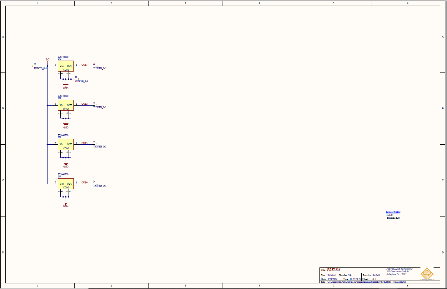
Figure 002: Schematic print of the carrier board. The carrier board consists of four MEMs elements and jumpers (through-hole pads) to provide an interface for power and signal on the board.
Why Four MEMs Elements?
Electrical noise, well any noise for that matter, is a complicated phenomena. It would take far too long to discuss noise at length, but the basics will be discussed here. For electrical systems, any passive and active component that has a voltage drop across it will produce some form of noise. Here, it is assumed that active components will have a broadband white noise signal from which the output signal rides on. Since noise is inherently random, and therefore completely uncorrelated, the output noise from active electronics can be averaged out. Board layout, and other forms of coupling make this not exactly true - but to a first order approximation it works. By tying the outputs of multiple noise sources together in parallel (via small valued resistors) the output noise floor has an overall reduction which therefore increases the signal to noise ratio. Condenser microphones have excellent signal to noise ratios with typical sensitivities being on the order of 50mV/Pa. By using four MEMs elements in parallel, the overall signal to noise ratio is improved at minimal effort and cost.
IEPE
IEPE is a type of two wire interface for measurement and DAQ systems which outputs a constant current into the load via the positive and negative (two wire) nodes. Typical current values range from 2-20mA, NI devices being on the low-end of that spectrum at 2.1mA of excitation. IEPE works on the principal that since constant current sources can operate into a wide range of operating voltages (the compliance voltage) the sensor can modulate the compliance voltage with output signal and the excitation current will still flow downstream into the sensor to power the device. Typical compliance voltage maximums exceed 20VDC and typical operating points are in the 10-15VDC range. The circuit here is designed to operate at the bottom of the current range (2.1mA) and has an operating point (compliance voltage) of around 13VDC.
The adjustable Zener diode U2 along with the resistor R3 set the power rail for the active electronics. This Zener needs enough cathode current to remain stable while it powers the four MEMs and the four low power operational amplifiers on the motherboard. The second Zener, U3, has no such current set resistor for its cathode as whatever current from the 2.1mA of excitation which does not flow into U2 or the active circuitry powers its cathode. The output of the four operational amplifiers (which are tied together via the averaging resistors) are connected to the anode of the U3. The Zener will always produce a regulated voltage across its cathode->anode, so the output produced from this configuration is the compliance voltage + the output AC signal. Analog devices has an informative application note on IEPE power and can be seen in the references.
Summary
Two circuit boards work together to house four MEMs microphone elements and provide the necessary output conditioning and power generation to interface with readily available DAQ units with IEPE power. The output sensitivity is calculated to be approximately 13mV/Pa if TDK ICS-40300 elements are used. The MEMs carriers were assembled by the production house (this project used PCBWay exclusively since they are the cheapest around) but the motherboard can be soldered by hand to save money. The total BOM cost, including assembly, for ten units is less than $30 USD per unit.
Mechanical Design
The two boards need to be fixed into a mechanical assembly and be 3D printable. The files were drawn in SolidWorks and can be seen in the renderings and images below.
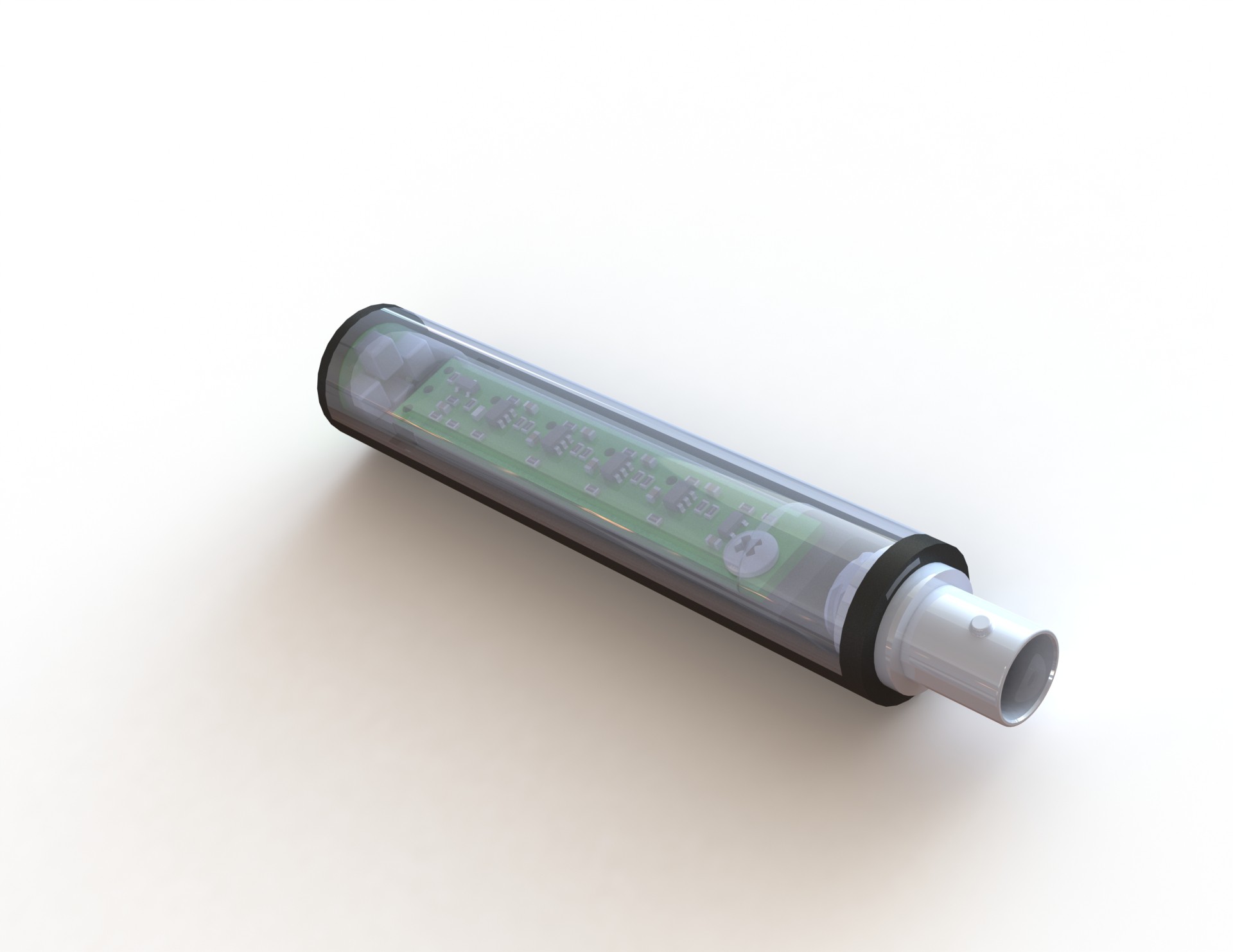
Figure 003: The SolidWorks assembly can be seen as rendered from the application. The MEMS carrier board is inserted on one end, and the BNC connector on the other. The carrier board is held in place by a single screw which self-taps into the PLA.
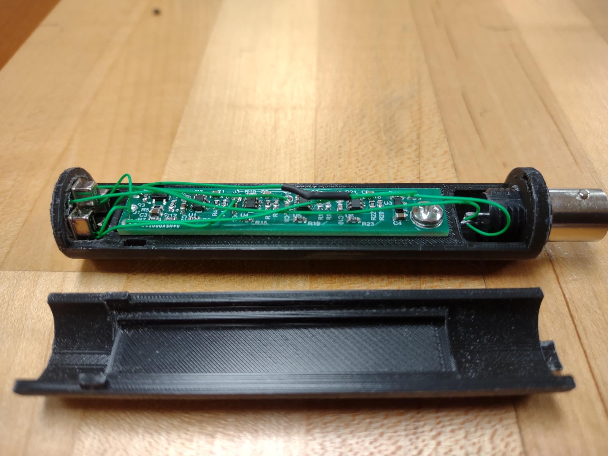
Figure 004: The as-built prototype can be seen here. The assembly is comprised of two 3D printed parts. The electronics get built into the base, and the lid is designed to be mechanically fit into the base.
The microphone is nominally 1/2" in diameter and almost identical in size to the majority of similar microphones available to purchase. Since the entire mechanical assembly is an arc, it is quite rugged and can be tossed around without fear of damaging or cracking the case. The opening for the MEMs carrier board will need future modifications as there is very little material and large stress concentrations acting on the layer-to-layer bonding. For now, it works just fine though.
Experimental Verification
To test the microphone, its performance is checked against the PCB PIEZOTRONICS 378B20 free-field condenser microphone. The microphone was chosen as it is laboratory grade, and therefore has a flat frequency response in a free-field acoustical signal through the audio band. The data acquisition system used is the NI 4431 from National Instruments.
Two measurements were carried out in a semi-anechoic chamber (not sufficiently anechoic/quiet below 200Hz): frequency response and noise. The noise measurements indicate what type of signal-to-noise might be achieved or expected and the frequency response indicates the overall sensitivity and flatness differences between the MEMs microphone and laboratory microphones that are readily available.
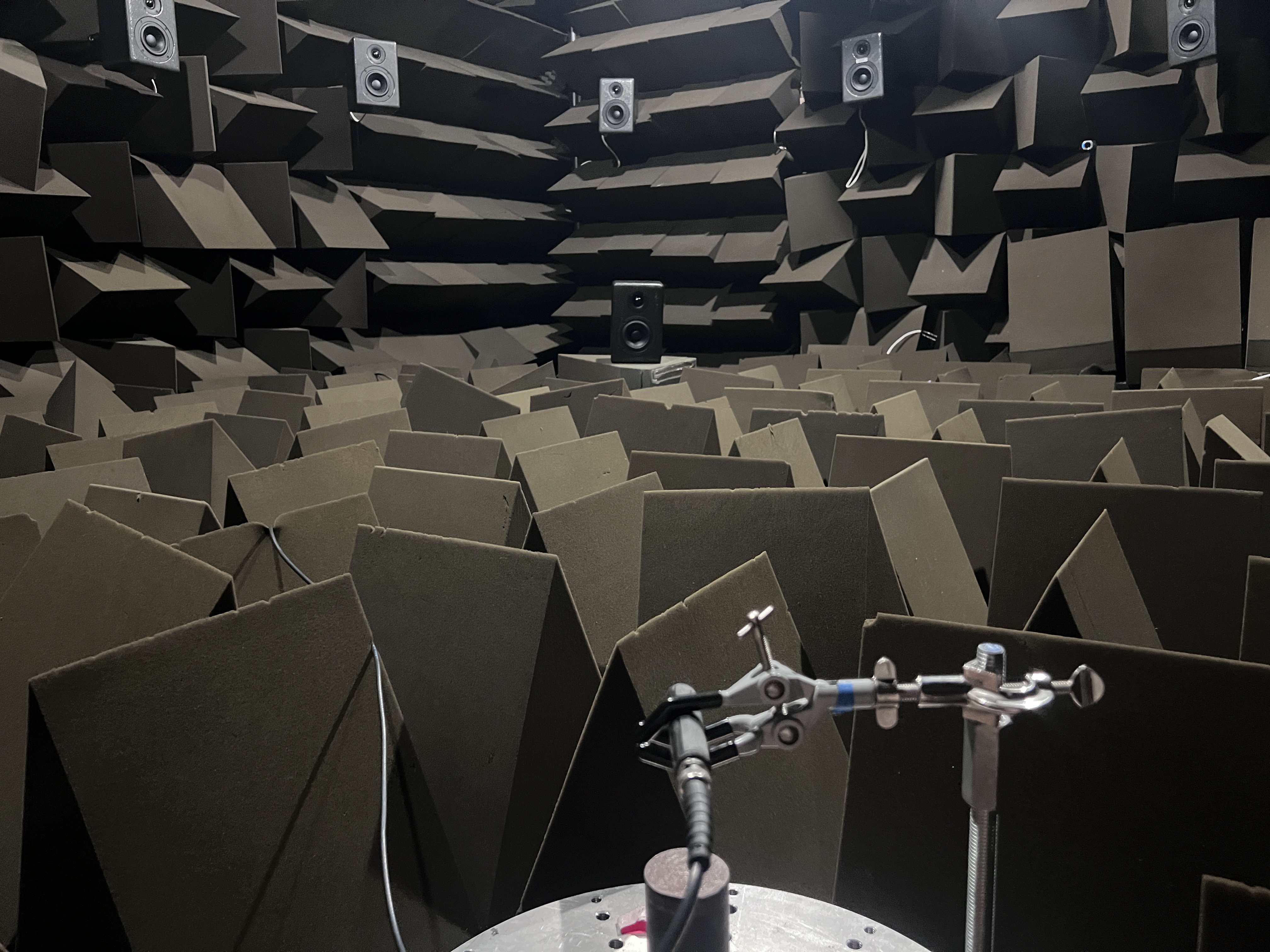
Figure 005: Figure of the MEMs microphone mounted on a turntable/arm and pointed at the loudspeaker in the semi-anechoic chamber. This configuration was used for the on-axis frequency response measurements of the microphone.
Noise Measurements
The noise measurements were taken by turning off the loudspeaker, powering the microphone on in the chamber and simply measuring the voltage waveform. The voltage output can be analyzed as well as the pressure response (using the calibrated sensitivity and the voltage timeseries one can convert the voltage to pressure in pascals).
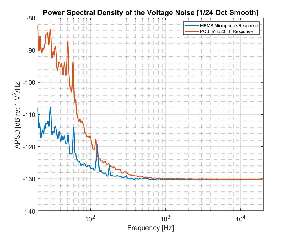
Figure 006: Power spectral densities (PSds) of the output voltage of the MEMs and PCB microphone. Below 200Hz, the PSD of the MEMs microphone is much lower than that of the PCB microphone. In part, this is because of the decreased sensitivity of the MEMs microphone, but it is still interesting to see. Both microphones converge to the same noise floor at higher frequencies, but the noise floor of the NI 4431 might be dominating here.
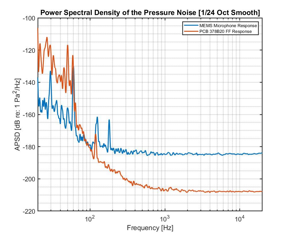
Figure 007: This figure shows the noise of the microphones in pascals (using the sensitivity of the two microphones). At the time these measurements were taken, accurate calibration data for the MEMs is not available. The nominal sensitivity of 13mV/Pa was taken for granted and used here. The PCB microphone was accurately calibrated using a B&K Pistonphone with ambient pressure corrections. Below 200Hz, the MEMs microphone might still have better signal-to-noise, but the chamber's room acoustics is impacting the measurement in that range.
On-Axis Frequency Response Measurements
The frequency response (FRF) can be measured by playing a frequency sweep into the loudspeaker and measuring the broad-band signal with the microphone. Using common two channel analysis techniques, the FRF can be estimated.
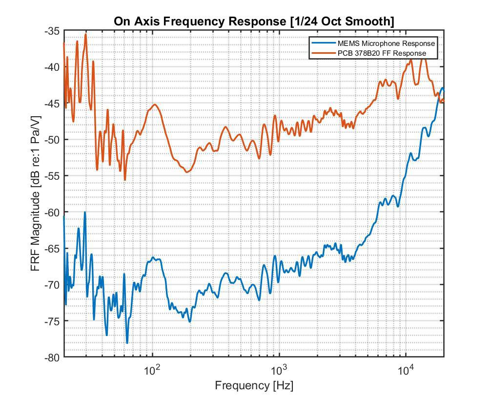
Figure 008: Here, the FRF of the two microphones is compared. Aside from a noticeable difference in sensitivity between the two microphones, the trend in data is well matched in the audio band up to about 10kHz. These peaks and valleys are not necessarily from the microphones frequency response - the FRFs of both the loudspeaker and the room acoustics are impacting this measurement.
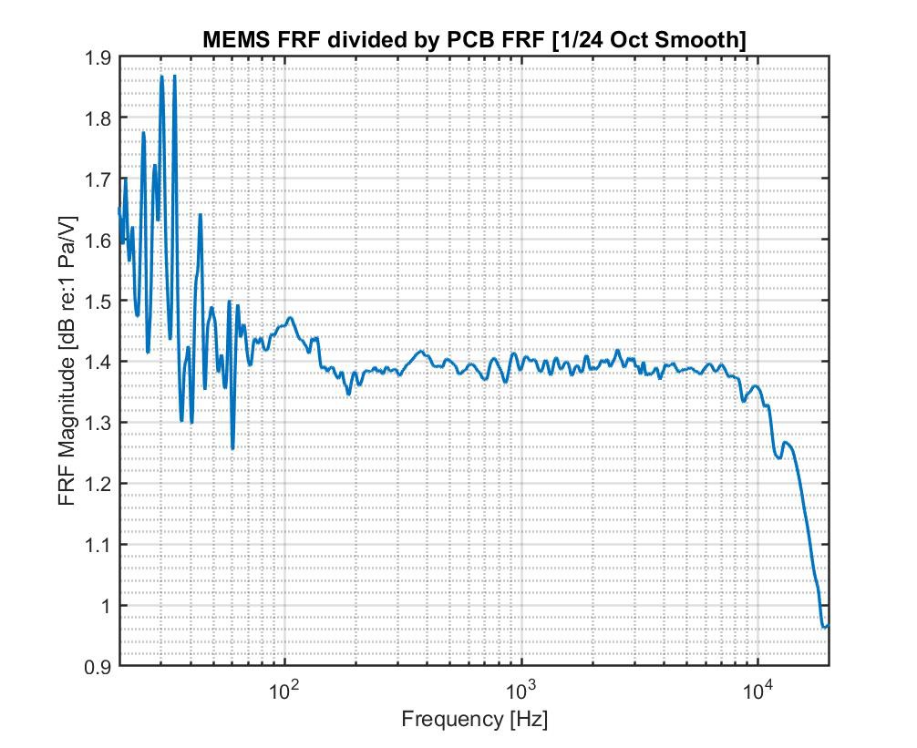
Figure 009: The PCB microphone is taken to be maximally flat since it is a $1000 microphone and laboratory grade. If the FRF of the MEMs microphone is divided by the FRF of the PCB microphone, its response can be equalized by accounting for the response of the loudspeaker and chamber. This is illustrated here and it can now be seen that the FRF of the MEMs microphone is very flat in the audio band up until around 10kHz. The data below 200Hz may or may not be valid since the chamber is not quiet there.
Conclusions
The MEMs microphone is cheap enough to be built by most anybody, and its response is impressive. The frequency response is sufficiently flat in the audio band, and its sensitivity (though less than the PCB microphone) is good enough for real measurements. Below 200Hz, its performance might even be better than the PCB microphone.
Additional experimentation needs to be done to more rigorously characterize the microphone. But, the preliminary results are very promising and the price makes it impossible to ignore.
References
CN-0532 (rev. 0) - analog devices. (n.d.). Retrieved June 7, 2022, from https://www.analog.com/media/en/reference-design-documentation/reference-designs/cn0532.pdf
The article was first published in hackaday
cr: https://hackaday.io/project/185762/gallery#68a0762979852867647a18eae0e99579
author: eter Riccardi


