

In this post, I decided to crack open one of my USB battery packs to see if I could add a telemetry interface. Now it’s time to actually add that interface.
SAFETY
Disassembling battery packs can be moderately dangerous. I’m an expert, so don’t attempt to disassemble any batteries of your own unless you have experience doing so.
GOALS
I wanted to know the following:
Battery Voltage
Potentially multiple voltages depending on how many cells are in series.
Charging current
Output current
BATTERY CELLS
Opening up the battery pack, the first thing I wanted to inspect were the battery cells. There are four cells it seems. Peeling back the squishy foam gently reveals that they are LG MH1 18650 cells.
The data sheet lists these official specifications:
Nominal capacity: 3200 mAh
Minimum capacity: 3100 mAh
Nominal Voltage: 3.63V
Standard Charge: Constant current 0.5C (1550mA), Constant voltage 4.2V, End current(Cut off) 50mA
Max. Charge Voltage: 4.2 ± 0.05V
Max. Charge Current: 1.0 C (3100mA)
Standard Discharge: Constant current 0.2C (620mA), End voltage(Cut off) 2.5V
Max. Discharge Current: 10A
Weight Approx.: 49.0 g
Cycle life: 500 (0.5C charge and discharge)
Operating Temperature: Charge 0 ~ 45°C, Discharge -20 ~ 60°C
Storage Temperature: 1 month -20 ~ 60°C, 3 month -20 ~ 45°C, 1 year -20 ~ 20°C
View fullsize
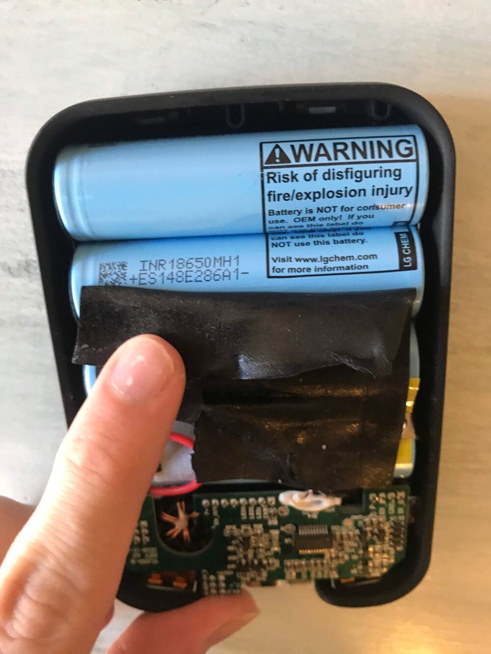
I couldn’t get a good picture, but the cells are all placed in the same orientation and connected together via two nickel strips that are spot welded to each cell on the positive and negative side. This means that the cells are all connected in parallel.
The cells have a maximum voltage of 4.2V, so this means that the control electronics must be boosting the voltage to the 5V output.
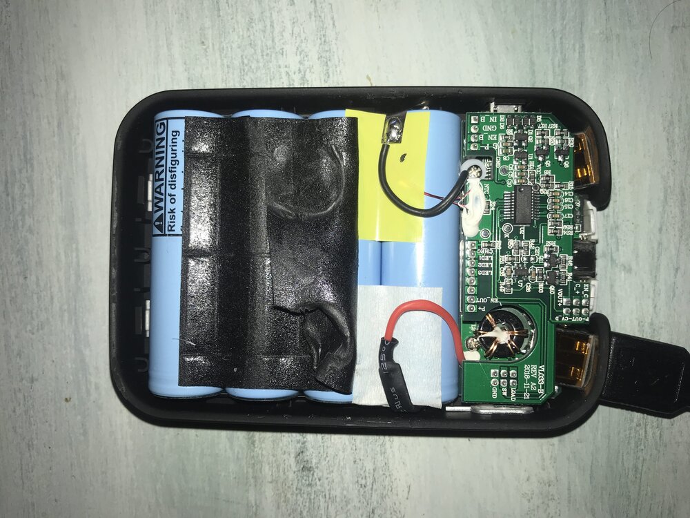
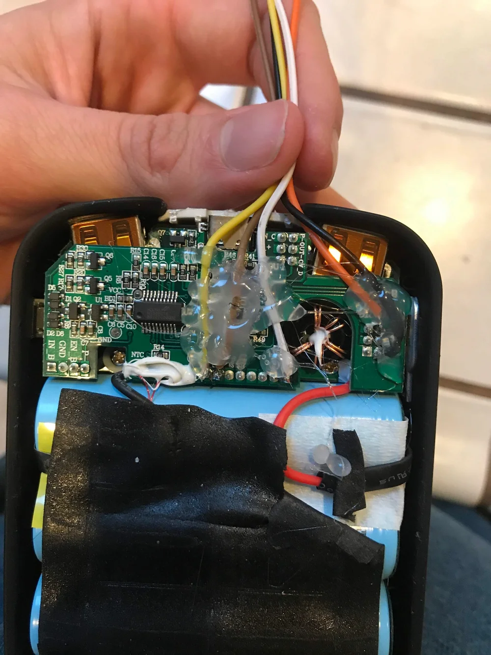
Now I moved onto the control board. There are actually two boards stacked on top of each other. You can see the bottom one have the USB ports soldered to it below.
View fullsize
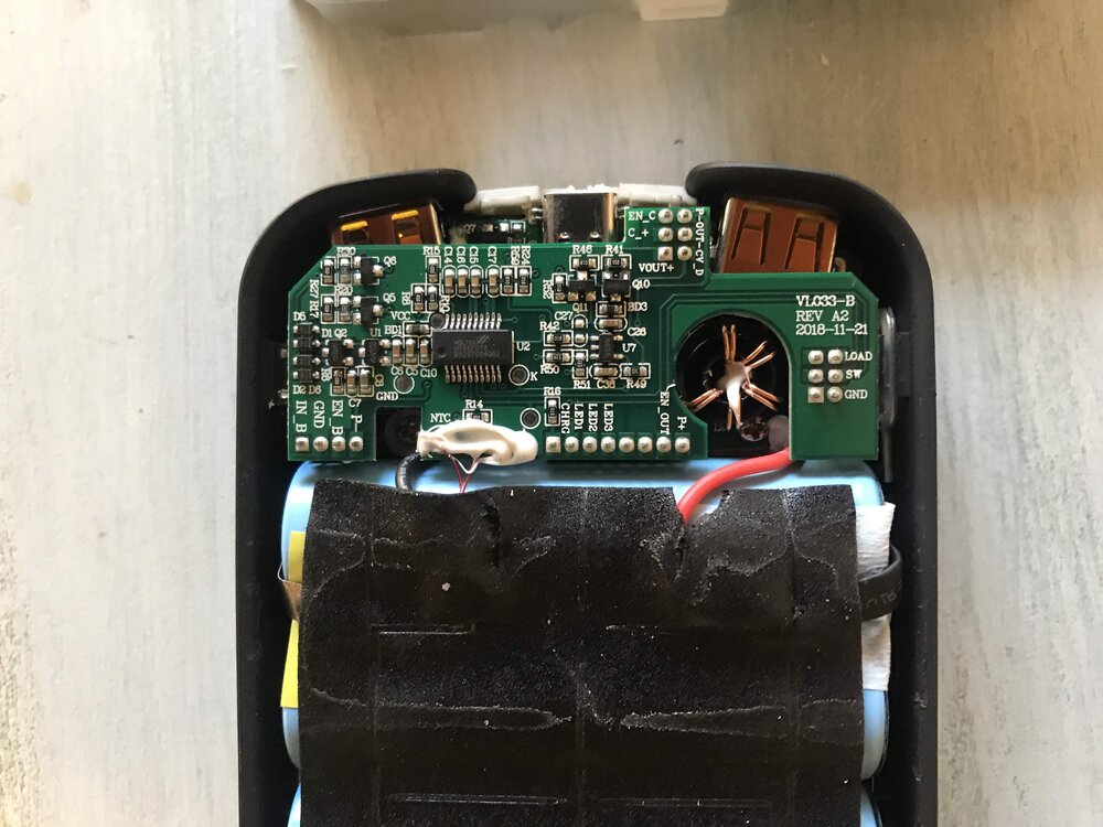
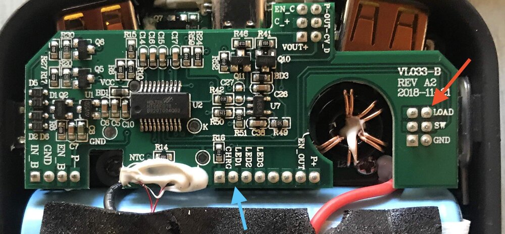
The first thing to do is always to read the silkscreen. Looking through things, it became pretty obvious where I could find the positive voltage of the battery cells on the top circuit board. The pin labeled “P+” seems to match exactly the battery voltage, so that looks like a winner.
View fullsize
The charging and discharging currents were going to be trickier. Many battery packs use an off the shelf battery management chip. I hoped to find one here that I could interface with directly via a digital protocol like I2c or SPI.
Looking at the main board, the chip is labeled HT66F018, which appears to be a general purpose microcontroller. This means the manufacturer of this pack has written their own software, which will make it difficult for me to directly interface with that chip.
Most battery management systems I know use a resistor to measure the current flowing through it. My next best hope was to find pins to measure that voltage drop across the resistors to determine the current flow.
Looking around at the silk screen I noticed two pins that stuck out: the one labeled “LOAD” and one labeled “CHRG”. Hopefully those would be my two pins.
View fullsize
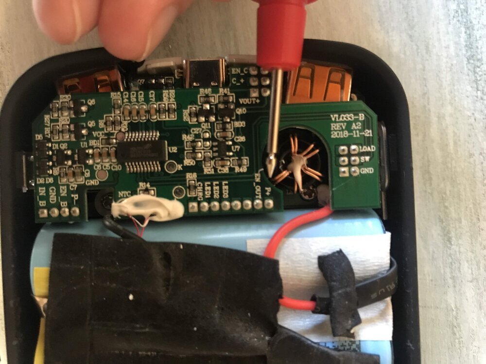
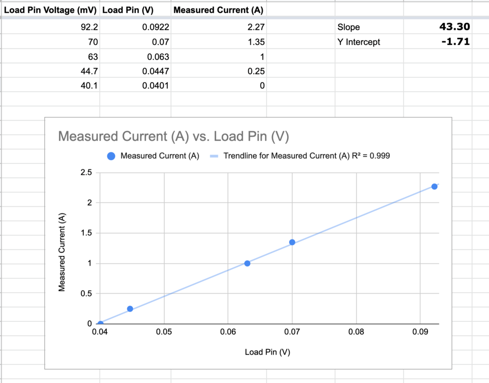
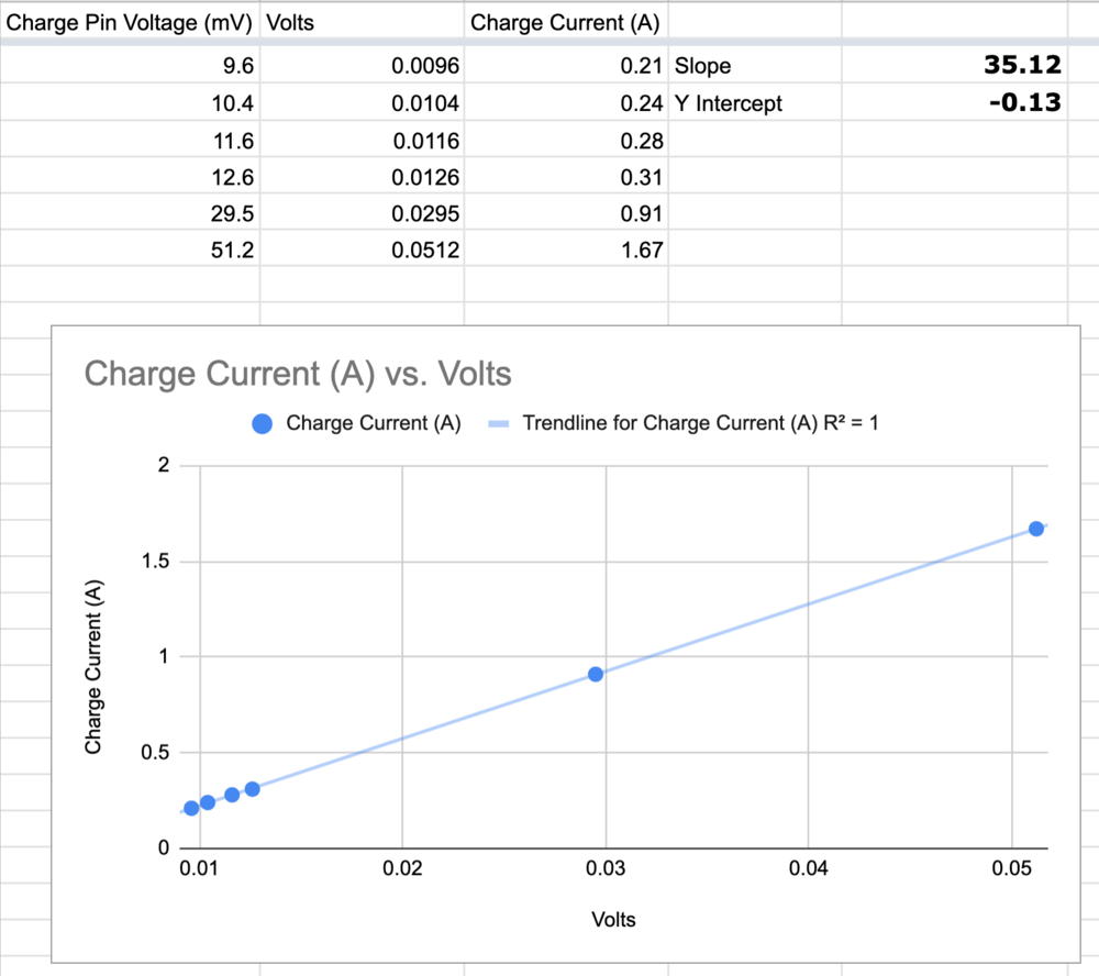
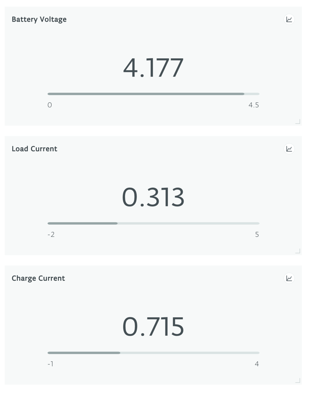
I spent a really long time making measurements with the multimeter and came up with the charts below for both the LOAD and CHRG pins. I validated each current measurement with a USB power meter.
Luckily it seems like both of the pins are exactly what I thought they were. The measurements seem to be super linear and they are confirmed by my external measurements.
View fullsize
My testing revealed that the “LOAD” seems to be the sum of both the charging and discharging voltage’s when the pack is both charging and discharging. That’s good to know and I took that into account when writing my software.
With my reverse engineering complete, I soldered some classic jump wires onto those three points plus a ground reference. I realize that I should be making differential measurements for everything, but I determined that this pack was probably common grounded and I didn’t need this project to be that accurate.
View fullsize
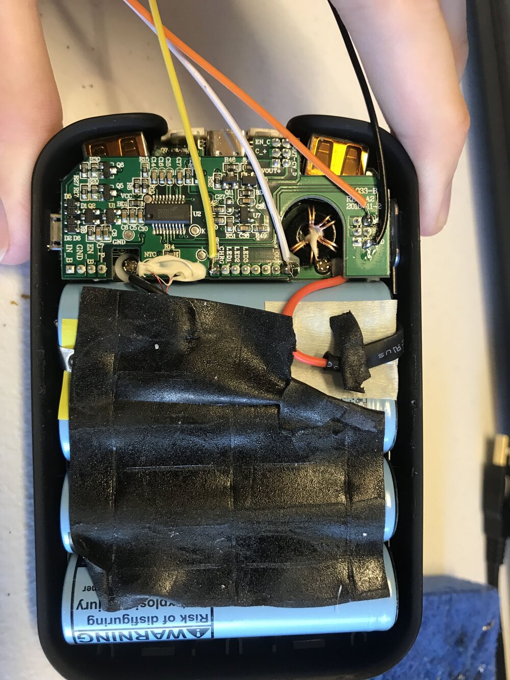
Now I just need to route these wires out of the case somehow. I tacked everything down with a bunch of hot glue and bundled them together going out a small notch I cut in the case.
View fullsize
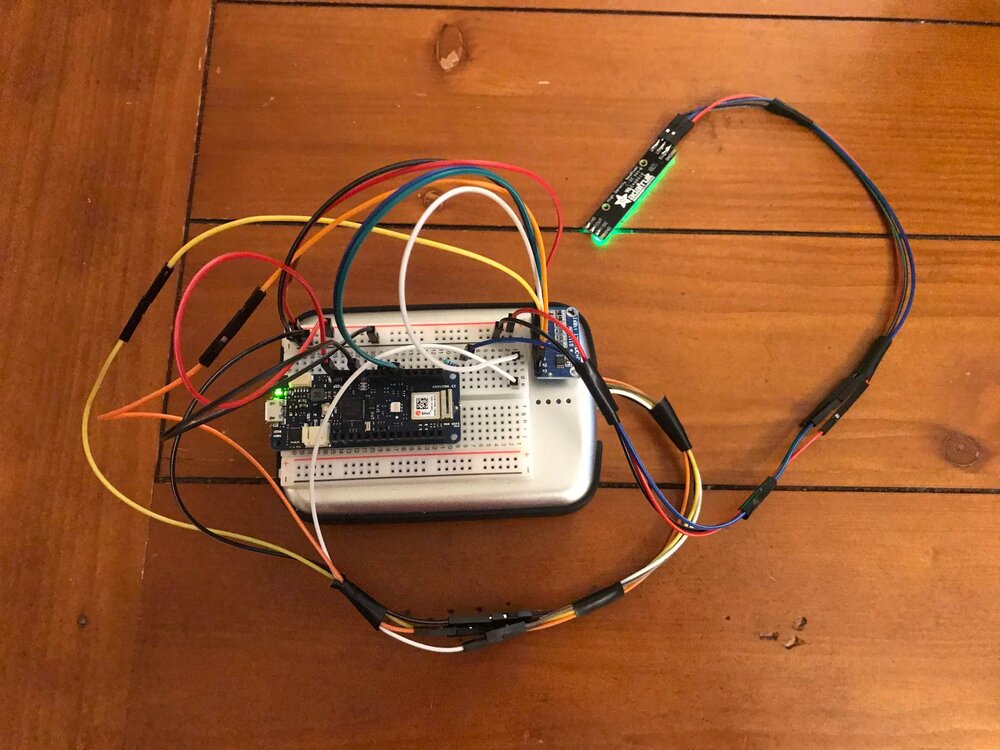
I routed those voltage connections to a small Arduino MKR with an ADC module I had laying around. I even added some Adafruit Neopixels to show green if the charging current is greater than the discharge current and red if the opposite is true.
And there you go, now I have a nice battery pack with a telemetry interface I can use.
View fullsize
I completed this project in just a few hours due to a time crunch, so it’s extremely likely something is not ideal or inaccurate, but generally it has been doing very well and seems to be accurate.
I hope you learned something from my post!
The article was first published in keenanjohnson [https://www.keenanjohnson.com/engineering-miscellany/battery-bank-reverse-engineering]
cr: https://www.keenanjohnson.com/engineering-miscellany/battery-bank-reverse-engineering
author: Keenan Johnson


