
I will describe the process of creating a tank with a camera that is controlled from a smartphone via Wi-Fi. Using Arduino, ESP-32 and Unity

Things used in this project
Hardware components
Hand tools and fabrication machines
Soldering iron (generic)
USB UART programmer
Story
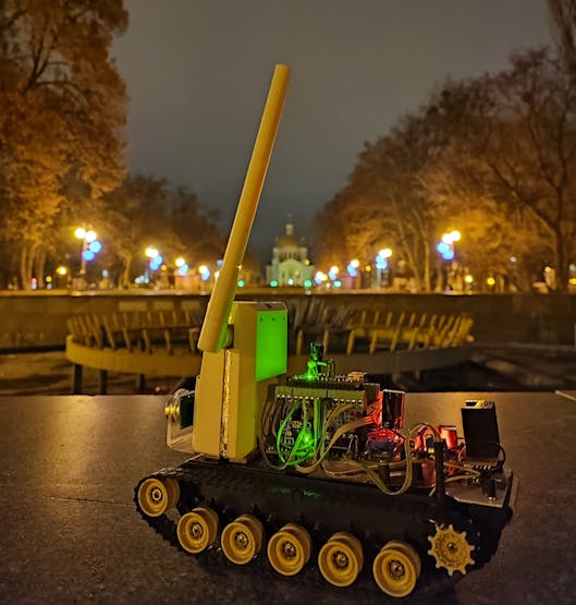
Would you like your own remote-controlled tank? I will describe the process of creating a tank with a camera that is controlled from a smartphone via Wi-Fi.
The main idea I want to convey is that you should not repeat this project, but make your own unique based on what you read here. I will show you an example of my tank, but the principles outlined here can be applied to creating other similar remotely-controlled vehicles.
Useful information
I will write subsidiary information like this. This information is unnecessary to read but still useful
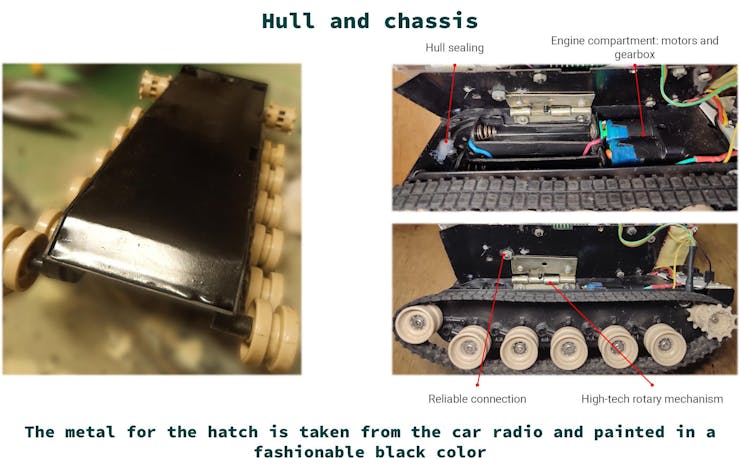
Hull and chassis
What and how you can place on your vehicle is determined by the hull, and the cross-country capability and speed depends on the chassis. For example, if you want to have fun racing in the street you should choose a chassis with great clearance and preferably with some kind of suspension system, but if your equipment will ride exclusively on the flat floors of your house and without overcoming such difficult anti-tank obstacles as terry mats, then you may not bother - any chassis will do.
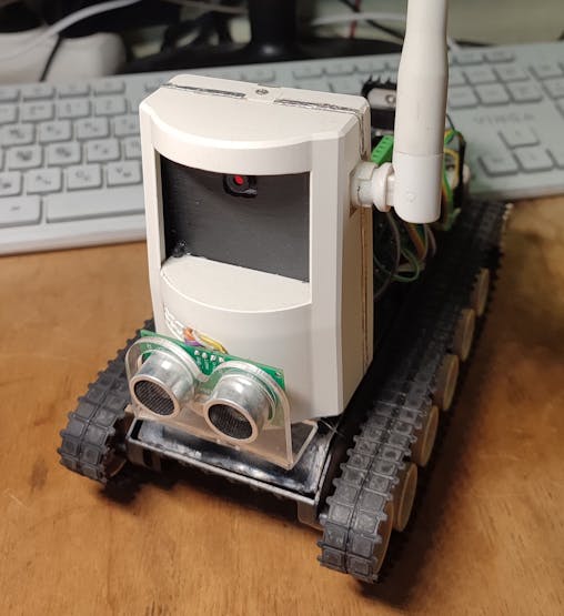
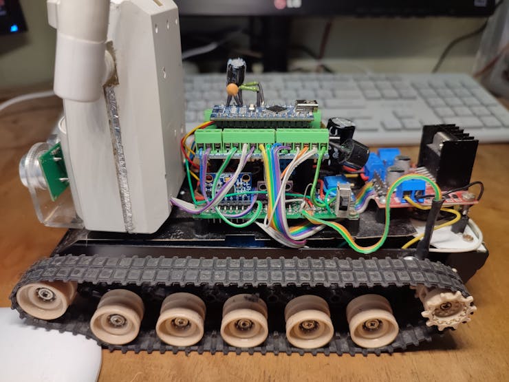
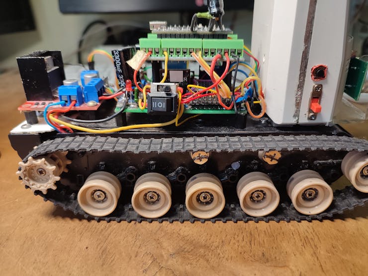
In my tank I used a hull from a toy tank, having milled everything inside that was superfluous, to increase the useful volume. I filled all the unnecessary holes with hot melt glue. The gearbox and motors was already installed on the toy tank.
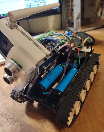
For ease of access I replaced the upper part of the hull to a hinged metal hatch, on which contains the main components of the tank. Under the hatch is the engine compartment – two motors + gears and a battery compartment with two batteries. Hinge for hatch is a furniture hinge (probably a brutal solution, but that's what I wanted).
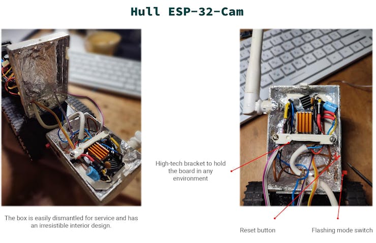
The hull for the ESP-32-Cam (white box with antenna) is an upside-down hull from the infrared motion sensor (BV-201). It is spacious enough and separates into two parts, which makes it easy to change something in it.
Power supply system (on-board network)
The reliability of your equipment and the duration of its autonomous operation depend on this system. You must ensure that the entire device is stably powered under any, even the worst, conditions. When everything is turned on at maximum, the voltage should not drop to the level where glitches or reboots will occur.
There are several ways to achieve power stability:
Create conditions such that it is impossible to use more energy than the device can provide - for example, software protection or physical limitation. Separate power supply for the power part – motors and powerful consumers separately from the intellectual part – microcontrollers, sensors. This way, if there is a voltage sag in the power part, for example, because of a jammed motor, you will avoid a voltage sag for your control - microcontrollers. Providing some kind of short-term protection against voltage sags can help in most cases and is easy to implement. An example would be a power capacitor for the microcontroller.
The main idea is that a voltage sag for microcontrollers is very bad, because it means loss of control over the whole machine, with all the consequences...
The tank battery consists of a pair of 2000mAh lithium batteries. Then the battery is connected to a DC-DC step-up converter MT3608, which forms a stable 5.1V for the onboard power network. The 0.1V margin is needed to reduce the effect of voltage sag on the wires and diodes.
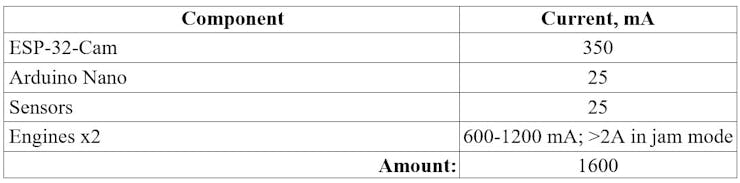
Current consumption of my tank
From the values above, you can see that the biggest consumers are the engines, which, in addition, have an uneven power consumption depending on the terrain on which the tank travels.
All connected equipment on the tank is powered by 5V, which comes from the stabilizer. Those sensors that need 3.3V are powered by the stabilizer on the Arduino Nano due to their low consumption. The board with the ESP-32 has a stabilizer that converts the input 5V to the 3.3V needed by the ESP.
Near the supply voltage input of the Arduino and ESP boards there are electrolytic capacitors with a locking diode. Because of the diodes the supply voltage decreases, for example for ESP a Schottky diode had to be used (because of its small voltage drop). But this small capacitor capacity ensures powering of the microcontrollers during short power dips when the motors are running, or as the batteries are drained. Without this, they would freeze dead or reboot. This measure extended the battery life of the tank by about 40%.
The motors have 0.1 µF ceramic capacitors on them to damp the brush sparks and eliminate interference in the power supply. The blocking capacitors are also near the power input on each microcontroller board, to protect against interference.
Microcontrollers
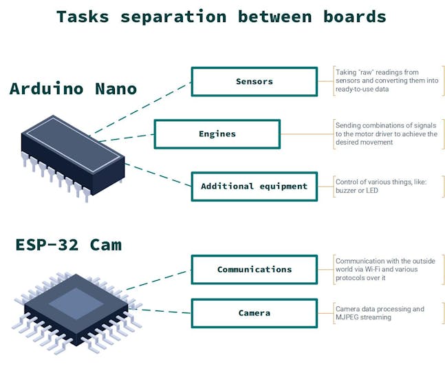
For my tank I decided to divide the logic into two parts. One microcontoller will process data from the sensors, move the motors and do other “simple things”. The second microcontoller will handle the camera and communicate with the outside world via Wi-Fi.
ESP-32 in the form factor of the board with a camera - I needed something cheap and that it would be with Wi-Fi and was able to work with a camera. This is the best option that I have found. The ATmega328p as Arduino Nano board is the perfect board by size and has many free pins and all necessary interfaces. A classic and reliable choice for tasks like sensor reading and motor controlling.
Why I chose two microcontollers:
I wanted maximum responsiveness from the Wi-Fi connection, so any extra task on the ESP would put an extra load on it, and even though it is dual-core this could lead to additional delays, which is not an allowed luxury.The ESP-32 board in the ESP-32-CAM module form factor unfortunately has very few free pins, and some of them are reserved for other needs. Some of the Arduino libraries do not work well on ESP. I like this idea of separation of duties.
Funny bug with ESP-32 and GPIO0
Before flashing the ESP-32 it is necessary to put it into boot mode. This is done by shorting the GPIO0 pin to GND. There is a switch on the tank (red switch), which puts ESP into firmware mode or into normal mode. But I ran into a poorly documented bug/feature. In normal, working mode, some special high frequency signal is generated on this pin, violations of which lead to various glitches of the whole ESP. Although the contact has an internal pull-up to the power supply, but it wasn’t helping to reduce the interference in wire that leads to the switch (about 7 cm), because of this there were occasional board freezes. By disconnecting the wire from the pin, the problems disappeared. I found out it was a rare bug (probably my board was defective). Replacing the board helped me.
Software and firmware
I used the Arduino framework, so you get a single ecosystem on Arduino and ESP, although the ESP has its own framework with excellent documentation.
This project uses the espressif32 platform version 3.2.1, because versions higher than that broke the memory allocation algorithm, which can cause ESP to reboot. This only applies to my case because I use several protocols such as HTTP, SSE, Websocket and frequent data transfers. In other scenarios everything works fine.
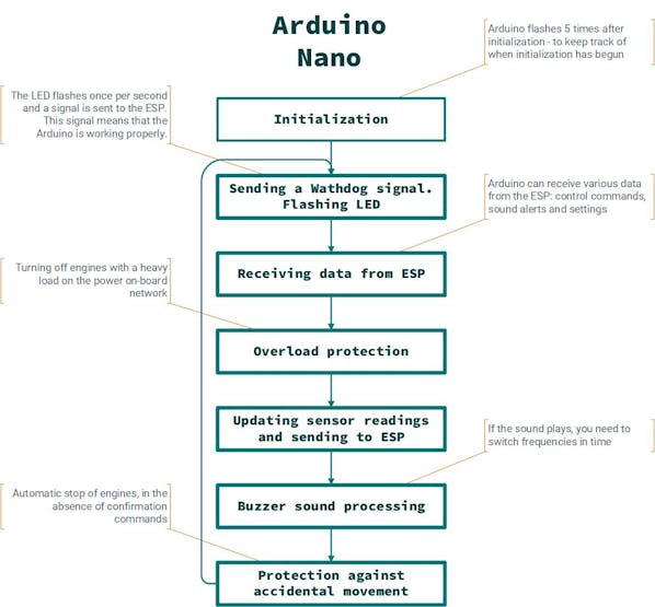
Algorithm of the tank operation. These are work cycles in general terms. My diagrams cannot be called an exact description of what is actually happening, for that it is better to see the code. I only showing the main aspects.

Error protection. Since bugs and crashes are unavoidable, especially during debugging, I had to make some elegant hack and called it "error protection".
There is such thing as a Watchdog. Watchdog is a hardware timer that counts backwards all the time, and if it reaches zero, it resets the microcontroller. In normal operation, the microcontroller should periodically reset the Watchdog, bringing its time back to its original state. If suddenly the microcontroller is thinking and does not have time to reset, the Watchdog will yank reset switch - simple and effective.
The Arduino can run out of RAM very quickly. I decided to put a watchdog that would keep track of the board and, if something happens reboot it. Unfortunately, the Arduino Nano has such a native boot loader implementation that my board would go into eternal restarts (Arduino WDT bootloop). You can fix this by flashing another bootloader (like optiboot), but this is too boring solution so I decided to organize the watchdog with ESP-32.
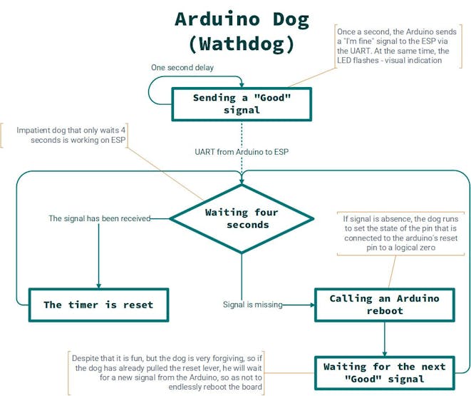
On ESP everything is much more boring than on Arduino, there are two protections against errors. The first to protect against a RAM overflow during an intensive data transfer by using integral watchdog for 4 seconds. In case of a freeze the board will restart, and the speed of rebooting allows not even to notice a break in the Wi-Fi connection (no reconnection is required).
The second - the brownout detector was turned off. This was done so that in conditions of 5V voltage, it would be possible to work longer. Now, in case of real brownout due to lack of power, the board will freeze, but this is compensated by software protection against motor overload (more below) and most importantly - increased battery life, because the detector has a little bit overrated threshold.
Motor overload protection. Despite the name, this software protection does not protect the engines, but protects the on-board power network from voltage sag to a critical level. Since the engines are the biggest consumers of energy on the tank, I made a protection, which at a voltage below a certain level - stops the engines (thereby reducing the current consumption), this saves from most restarts or hangs on the power.
The algorithm of motor overload protection is implemented on the Arduino, the voltage is measured by its internal ADC. Here's what algorithm looks like:
At some interval (5 ms) the battery voltage is measured. If the voltage is below the threshold, and there was no such thing in the last measurement, it simply remembers this fact. If the voltage is below the threshold, and in the last measurement was also lower, the protection is triggered and the motors will be stopped.
I tried to soften the effect of voltage sag from the transients (at the moment of changing the side of motion) by smooth acceleration of the motors, but this had no tangible effect (probably on large motors it would have given better results), moreover dynamics control was lost because there was a delay while the motors were accelerating.
Sound signals. Sound alerts are a cool thing, they let me know if something happened to the tank or if it is ready to work.
I have four beeps in total:
"Notification" - the loudest. It is for scaring folks on the streets (so they won’t step on the tank by accident). This signal can be called manually from the control app. "Warning" - something happened, but not critical, such as engines was stopped due to low voltage. "Error" - something has broken so that the tank can no longer function, without intervention or rebooting. "Good" - means that everything is fine. Currently used as an indicator that the tank is ready to go.
All signals consist of a set of four parts. Each part stores the frequency and duration of the sound, a special function switches frequencies during the sounding of the signal. This alarm system is simple to implement and easily scalable.
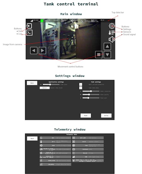
Tank control terminal (app)
This is an application that provides: motion control, viewing data from sensors, conducting diagnostics and adjusting the tank. The application was made using the game engine Unity. The Unity is not designed for this task because that is game engine after all. I choose Unity just for fun.
The functionality of the application consists of:
The main screen, which contains buttons to control the movement of the tank, buttons to navigate through the application windows, the top panel with sensor data and additional information. The top panel contains data from the main sensors: speed, distance to the nearest obstacle (ultrasonic), slope of the tank, voltage and battery level. Also, there is the level of communication with the repeater, an indicator of the quality of communication, the last motion command that was sent to the tank and the number of received frames from the camera per second. The log window where Arduino, ESP and the application itself can record all sorts of events - handy for debugging.Button to start the acoustic suppression weapon - the sound signal. Settings window - you can adjust the video scale, restart the stream, overload protection on/off, automatic video adjustment, as well as adjust the quality, resolution and gain of the video camera. Telemetry window - output of data from all sensors and quality of communication.
Algorithm of the application:
Search for the tank in the Wi-Fi network, if found - establishing a connection with it. Video reception and display. The video quality is automatically adjusted if necessary. Receiving data from sensors. Receiving data in the log. If there are control commands - send them to the tank. If the connection fails, an attempt will be made to reconnect.
Controlling the movement of the tank. Initially I had the idea of controlling the tank with two virtual joysticks. This idea was abandoned because the engines are very low-powered, and together with the gearbox does not allow you to develop large speeds, there is simply no speed control range. The maximum speed is low. But I am sure that if the tank could develop impressive speed, it would be cool - you could smoothly develop speed and drift on the tank.
On my slow-moving tank 8 directions of movement were enough: left, right, forward, backward and diagonally to turn the tank on the move. Each side of the movement (including the stop) corresponds to a number from 0 to 8.
As soon as the state of the control buttons changes, a number is sent to the tank by HTTP GET request, indicating the movement side. Every half-second the motion command is re-sent to the tank. In the case of movement, the tank expects that each command will be repeatedly sent no later than one second, if there is no command, then it stops. The command "STOP" is repeated only three times (even if it does not reach, the tank will stop by itself).
Thus, to move the tank constant confirmation of commands from the terminal is required, in their absence, the tank automatically stops moving. This redundancy allows you to achieve a guarantee of delivery of motion commands and avoid the funny situation when the tank is moving, and you cannot stop it because the connection is broken.
Communications
Reasons why I chose Wi-Fi:
I needed to transfer data, probably in the future quite large volumes. I wanted control (with video transmission) within a radius of about 30 meters on outside. Wi-Fi allows control from a smartphone. I like the technology itself.
There are two modes of connection with the tank:
External repeater antenna - this antenna has better qualities than the one in the smartphone.By physically placing the repeater somewhere between the smartphone and the tank.
Repeater mod needed to increase the communication range, which is achieved by several things:
External repeater antenna — this antenna has better qualities than the one in the smartphone.By physically placing the repeater somewhere between the smartphone and the tank.
Methods to improve Wi-Fi communication:
The ESP-32 operates in the 2.4 GHz Wi-Fi network. This means that anything on these frequencies and our not useful signal is an interference. You should keep this in mind, for example in some very noisy places your device will work much worse than it could.External antenna instead of integrated antenna. For a stable and distant connection, the native antenna is not the best. I used an external antenna from an old router for 5 dB (the native one is 2 dB).The ESP-32 supports three Wi-Fi standards: 802.11b; 802.11g and 802.11n, each with different data rates and conditions, such as signal sensitivity. Knowing your speed needs, you can change to a "simpler" standard and gain in sensitivity. For example, I use 802.11b on my tank, which provides only 11 Mbit/s (enough for data and video) but increases the sensitivity of the receive.If you are using the Wi-Fi standard: 802.11n, it makes sense to reduce the bandwidth from 40 MHz to 20 MHz. Because of the smaller operating frequency range, there is less chance of your signal overlapping with something else - less interference.The Wi-Fi on the ESP-32 uses a frequency range of 2400 MHz to 2484 MHz. In order for the devices not to interfere with each other, they operate on different channels (frequencies). If your device works in a place where there are many other Wi-Fi networks, it may make sense to change to a different channel to avoid mutual interference. On the tank, I chose channel 11 as the least popular channel.By default, the ESP-32 has power save mode (sleep) enabled for Wi-Fi. This is a great solution for some IoT stuff, but bad for devices where you need maximum response. Because of this mode Wi-Fi seems to "rest" sometimes, you can see it by large random delays. It is easy to disable - WiFi.setSleep(false). Turning this mode off, gives a smooth stable network response, if there are no other problems.If you are using Bluetooth and Wi-Fi at the same time, remember that the ESP-32 has a single radio module. Even though these two technologies operate in the same 2.4 GHz frequency band, their actual operating frequencies are dozens of MHz apart. Therefore, when operating on these two technologies simultaneously, the ESP will switch from one communication to the other, causing delays.
The principle of deploying Wi-Fi on a tank:
Firstly, the tank is looking for a Wi-Fi repeater point. If there is one, it successfully connects to it.If, under any circumstances, the connection to the repeater is broken, the tank will try again from the first step.If no repeater is found, the tank deploys its Wi-Fi point.
Funny hardware bug on the ESP-32 antenna
The built-in antenna may be poorly matched. This is very easy to check - try to ping ESP or watch video from it, if at that moment to put a finger to the antenna and the connection improves (less latency or higher FPS), then the antenna is of poor quality. As I understand it is rare occasion and it's all because of my love for cheap components. On the internet there are solutions like sticking a piece of antistatic bag or something similar, but in reality, these solutions are not very effective. I spent hours trying to figure it out and changed the antenna to an external one, I even wrapped foil around the ESP hull, though it's more to protect it from random noise in the street, and it's also pretty.
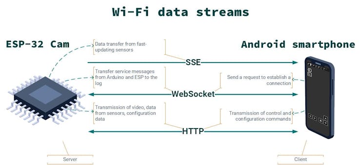
Data transfer protocols. Data exchange between the tank and the control terminal occurs via three protocols:
HTTP – only the client can start a communication session, the server cannot address itself first to the client. It transmits data from sensors, control and configuration commands.WebSocket (WS) – allows you to send data in two directions from the server to the client and vice versa. It is used as an initial "ping" to establish the communication mode and to transfer data from ESP and Arduino to the log.Server-Sent Events (SSE) – works on the principle of client-server subscription, but works only one way, from the server to the client. Transmits to the terminal some data from the sensors, which are quickly updated.
The main protocol used is HTTP. WebSocket and SSE I chose to gather experience with them. So, the use cases are a bit far-fetched, you could easily do without them. Also, the native asynchronous web server is pretty fast.
The choice of WS and SSE is based on two factors:
They allow you to send data from the server to the client directly. With HTTP, the client would have to poll the server.In theory, they work faster than HTTP, due to less data redundancy and unnecessary communication sessions.
Data update rate on ESP-32. The ESP has a certain limit on the amount of data it can handle approximately 15 packets/sec. If this limit is exceeded, the data is discarded with an "ERROR: Too many messages queued" entry in the UART. Note that the number of connections per second has more influence here than the amount of data.
Since I wanted a faster transfer, I decided to try to bypass this with WS and SSE. My traffic is almost always homogeneous, so everything was tested in the same conditions. Here are the results I got:
WebSocket - the connection amount limit is similar to the HTTP server. There are no benefits other than transferring from server to client directly.SSE - allows you to slightly increase the transmission limit by 3-5 packets per second.Both protocols are less stable than the HTTP server. For example, sometimes, ESP-32, may reboot or freeze when there is heavy traffic through them, as a reminder: "don’t mess with bypassing the limits". If you don't overdo it, you can use it.
The response speed of all three protocols is the same, you can't say that HTTP is slower than WS or SSE when transferring the same data. This means that the final implementation is more important than choosing any of these protocols for control or anything else that requires low latency.
The principle of data transfer. The data is transmitted as strings. Some of it is packed into JSON format, and some of it transmitted as it is.
The ESP-32 hosts an asynchronous HTTP server. It communicates via HTTP GET requests. The terminal transmits control commands to through request. In the parameter of which there is a digit, which corresponds to the movement side of the tank. Camera or Arduino settings are transmitted in a similar way. The terminal polls the data from the sensors periodically, receiving in response from ESP the last received sensor readings in JSON format.
WebSocket - sends service messages to the terminal to log and confirm that the Arduino settings have been accepted.
SSE is used for one purpose: to send rapidly updated sensor data to the terminal as soon as it is received from the Arduino.
Transmit data from sensors. The sensors are divided into two groups:
Slow sensors - updated at a certain interval and transmitted from the Arduino to the ESP. The control terminal (application) periodically asks for this data. Frequency of update is once in two seconds. Transmission via HTTP GET requests.Fast sensors - updated at a certain interval (faster than slow sensors) and transmitted by the Arduino to the ESP, then sent immediately to the control terminal. The update rate is 2.5 times per second. Transmission via SSE.
Internal communication. Arduino - ESP. The Arduino board and the ESP-32-Cam use the UART protocol for communication. At first, I made my own solution for data transfer, but when there was too much data to manage, I realized that it is much better to use ready-made solution.
This solution is the wonderful library SerialTrasfer, it takes the "dirty" work of data transmission: organizing the correct transmission of packets, checksum counting and allows you to transfer simple data types and structures, which is exactly what I needed, because I store data from sensors in the structure.
ESP-32 has several hardware UARTs on board, which, unlike the Arduino, can easily be reconfigured to other pins. UART_0 remains for debugging and flashing firmware and UART_1 for Arduino communication.
The UART speed for data transfer is set to 76800 baud/s. At this speed, there are the fewest transmission errors due to the 16 MHz clock frequency of the Arduino microcontrollers and the 320 MHz of the ESP. This solution makes it possible to largely guarantee the delivery of correct data between ESP and Arduino, without having to check and possibly duplicate them.
Because of the different architecture of the Arduino Nano microcontrollers (ATmega328) - 8 bit and ESP-32 - 32 bit, you need to use memory alignment so that the data (enumerations, structures) will be accepted correctly on both platforms. I use the attribute "attribute((packed))" for this purpose.
Given the different voltages of the ESP-32 (3.3V) and Arduino (5V) logic levels, the UART between them is connected through a level shifter.
The principle of data transmission via UART:
The data is transmitted in pairs: "Data type" and "Useful data", and the last one can be absent, because sometimes it is enough just the presence of the fact of transmission, for example the signal that it is necessary to update the wathdog timer.A total of 8 data types: "Sensor readings", "Control command", "Beep type", "Wathdog", "Log message", "Fast sensor readings", "Arduino settings", "Read Arduino settings".On the sending side prepares a message with the type of data in the beginning, followed by the useful data, if it is needed.The receiver receives the message and depending on the message type, there may be: some action or unpacking data.
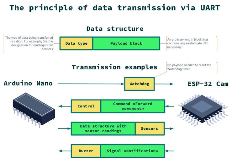
This simple system of data transfer is easily scalable, allowing you to transfer different types of data and introduces a little redundancy because the data types are only Enum, i.e., the usual numbers.
You can use not only UART, for example SPI, or I2C, or other data transfer protocol. I chose UART because of its good documentation, the ease of working with it, and the fact that it would still be needed - for debugging.
Sensors
There are a huge number of sensors for all occasions, they are needed to measure all existing and non-existing physical quantities. They are the "eyes and ears" of your device. With them, your device can perceive reality.
There are a number of sensors on the tank:
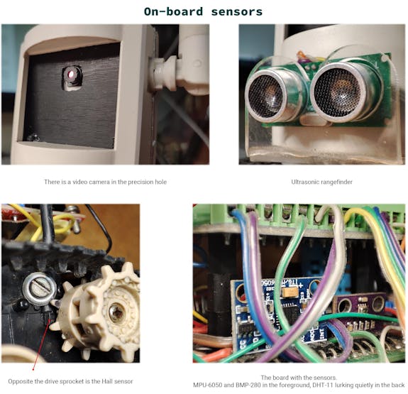
DHT-11 module thermometer and hygrometer. Not very accurate, but cheap and easy to work with. I think that on a tank (with telemetry) there should be a classic sensor - a thermometer.Hall sensor A3144, as tachometer. A small neodymium magnet is mounted on the drive sprocket on the left track and a Hall sensor is placed near it on the hull. The sensor reads each magnet that pass over it and by that calculate the number of revolutions of the drive sprocket. Knowing the diameter of the sprocket, you can find out exactly what distance the tank has passed and at what speed. The accuracy of this improvisation makes you to wish better, but it works coolly.Barometer BMP-280. Allows you to get the atmospheric pressure and based on that the altitude above sea level. The sensor has many operating modes for all occasions, but it is a bit complicated to set up.MPU-6050 accelerometer and gyroscope module. A good, fast sensor for measuring orientation in space. Uses complex mathematics to work, but this is compensated for by the many available libraries.US-025 ultrasonic rangefinder (analog of HC-SR04). It is used to display the distance to the nearest obstacle in front of the tank.
Funny bug with the I2C bus
Some sensors (MPU-6050, BMP-280) are connected via I2C. Sometimes because of this bus the Arduino Nano microcontroller can freeze up. I watched with an oscilloscope what was going on there on the bus and instead of the approximately flat rectangular shapes I saw horrible distorted fronts of signals, which were more like triangles or even random noise. I checked on several boards and without the tank but the result was the same. I never figured out what was causing it. Maybe it was because of cheap Arduino parts or maybe something else. A strong pull-up of the bus to the power supply via 1.3 kOhm helped.
Readings from the sensors can be processed directly on the Arduino or ESP, and heavy calculations can be processed on the control terminal (app). At the moment, the sensors have no practical purpose and are installed for training and as a basis for further tank upgrades, besides, they make the tank look like a "serious" device.
Camera, video receiving. The ESP-32-Cam module has a 2MP OV2640 video camera. The camera can capture the surrounding world in an amazing range of resolutions from 96x96 to 1600x1200. On the tank I use three resolutions: HVGA - 480x320; VGA - 640x480; SVGA - 800x600. The choice of these resolutions is due to: fast formation and transfer of this size frame, which gives a stable 25 FPS. Resolution higher than that is too big for a stable frame rate, and low-resolution cause too much image quality loss.
The basis of the code (the one on ESP) to work with the camera is the standard example "CameraWebServer". There is a separate HTTP server for the camera which, when connected to it, gives the client an endless stream of JPEG pictures from the camera - we get MJPEG stream. The camera server (not to be confused with the server for the data transfer) can only work simultaneously with one client, but I've seen examples of work with a large number of clients, I do not need it, so I did not bother.
Receiving frames is not a difficult task because the MJPEG stream is an endless transfer of JPEG images, it is enough to catch special markers (bytes). A marker always starts with the byte 0xFF, followed by a byte that denotes the marker type. Markers can denote different things, but we are interested in two types of markers: frame start - 0xD8 and frame end - 0xD9.
Unity cannot support MJPEG streaming by its own. I searched the net and found code examples but some of them didn't work, or were out of date, or had memory leaks. I didn't consider any paid solutions. Having looked through all of the examples that I found, I realized that nothing good for my task was available. I decided to make my own wheel. Since I used Unity for everything, I decided to use their UnityWebRequest method and their standard “multi‑threading” mechanism– Coroutine.
The principle of image reception is simple:
I made my own implementation of a handler (DownloadHandler), which just pulls an event every time passing a bunch of bytes (JPEG) there the moment the frame came in.Next the frame goes to the method (LoadImage), which tries to convert JPEG bytes into texture (Texture2D).If the method succeeds, the texture is stretched over the object in the scene. It is rendered and we can see it on the screen.
Corrupted MJPEG frame detection on Unity
The LoadImage method may fail to load a texture because it receives a corrupted frame. Although it should return false but it always returns true for some reason. But I took advantage of the fact that when it cannot load a texture, it gives instead a white texture with a red question mark, it is exactly 8 by 8 pixels in size. And I don't use that size in my tank, so a simple check for texture size on the output lets me know that a corrupted texture came in and avoids the epileptic's dream - a suddenly appearing white texture that would blink between normal frames. By the way, clever Web-browsers know how to render that part of the frame in this case, but I don't, so I have to use this elegant hack.
Camera frame rate on ESP-32. The camera itself is quite fast and fairly gives the manufacturer's claimed 25 frames in SVGA resolution, but there are nuances:
It is necessary to have PSRAM - it is an external RAM, it can store frames. Without it you cannot select a higher resolution and frame buffer size. Most of the ESP-32-Cam boards already have such memory.XCLK signal frequency - I don't know exactly what this parameter is for. As I understood the clocking signal for what internal needs of the camera. If I understand correctly from the documentation, it can be in the range from 6 to 24 MHz. But on the internet, they advise to set it to 10 or 20 MHz. I set it to 20 MHz. You have to be careful with this setting as it may not work correctly with some resolutions.The number of frame buffers - allows you to increase the FPS that the camera shoots. To increase the number of these buffers is exactly why you need PSRAM. Each buffer multiplies the FPS. I use 2 buffers.JPEG quality - the level of compression of the image can be in the range from 0 to 63. But in practice, with values below 10, the frame will be cut off because of its large size when transmitted over the network. I mostly adjust in the range from 16 to 63 quality. This setting allows you to significantly increase FPS on poor connections, at the cost of square artifacts in the image.
Even with a well-configured camera, you may see terribly low FPS on the receiving end. This happens because due to network delays, frames do not have time to change at the needed frequency. FPS depends a lot on the state of the connection, even more than it does on the right camera setup. For example, while you can receive 5 frames over the network, the camera can make 60 of them, but will not transmit more than you can receive. Therefore, it is necessary to be very attentive to the organization of communication.
Video Setting. The video has a lot of settings, some of which I made it possible to adjust directly from the application:
Resolution - three to choose from HVGA, VGA, SVGA.Quality - JPEG compression level.Gain ceiling - allows you to amplify the signal from the camera for better visibility in low light conditions, in exchange giving a lot of noise in the frame.
Auto-tune video. The ability to transmit high-quality video signal, and most importantly a stable frame rate falls as the signal deteriorates. In order not to mess with the camera settings each time manually, I made a function that adjust settings instead of me. The principle is simple:
Knowing the number of frames that come per second you can find out the FPS.As soon as FPS falls below a certain threshold, we lower the picture quality (JPEG quality), if there is no place to lower the quality, then lower the resolution.If the FPS is above a certain threshold, everything happens exactly the same way, only the quality and resolution increase.
It works not perfectly, but it is quite effective. This system is improvable. For example, you can more accurately determine the moment of "bad video signal" and expand the resolution range.
In my case the cheapest version of the camera is installed. For those who will do something similar with a first-person view (FPV), I recommend buying a camera version with a lens of 120°of view, because the usual with 66°has very sad result – it simply lacks field of view.
Actuators
This is what makes your device alive. For example, on my tank it is the two motors that drive it. It could also be some kind of laser and servos to point it.
Often actuators consume a significant portion of the on-board power. Since the microcontroller can only pass a small current through itself, it is necessary to control such devices through special "adapters" - drivers.
The driver is the board to which the microcontroller, actuator, and power are connected. The idea is that the microcontroller sends only control signals like "do this or that" and the driver itself figures out how to properly actuate the actuator. You can also generate the signal from the microcontroller, but then you have to make all the circuitry and implement the control algorithm. It is much more efficient and faster to use a ready-made specialized device - a driver.
For the tank I used the L298N driver. It would be possible to use newer and more efficient drivers. But I like to use such old stuff, which has a brutal look and a big, and most importantly warm heatsink after work - it gives the spirit of the tank and fits perfectly into its "built from what was on the table" design.
There are a total of 9 control commands:
"Movement": forward, backward."Turn": left, right."Moving with a twist": forward and left, forward and right, back and left, back and right."Stop."
Considering that the tank has slightly different motors, they have different maximums of PWM signals (maximum speed of the motors) for rectilinear movement.
The principle of motor control:
"Stop" command - a signal is sent to the driver to stop the motors."Move" command - the driver spins both motors forward or backward."Turn" command - the engine on the turn side rotates backwards, and the second engine forwards. This achieves a quick turn on the spot."Moving with a turn" command - the motor of the track opposite to the turn works at 100%, and the motor on the turn side reduces the revolutions, for example 70%. This results in a smooth turn to the side of the braking caterpillar.
It is possible to use more aggressive braking tactics, such as reversing or locking the motor, but given the small mass of my tank and the almost complete absence of inertia, this is excessive. In addition, the gearbox resists spontaneous movement, and also such a brake consumes a lot of energy for a short time.
To turn, you can shut off (stop) the track engine on the side of the turn. In this way you can achieve a nice radius turn on the spot around the track-brake.
As you can see there is nothing complicated about controlling an actuator. You just need to choose the driver that is suitable for your tasks, depending on the current consumption and the type of device you want to control.
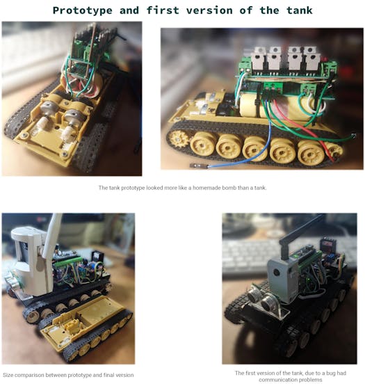
Photo presentation
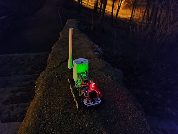
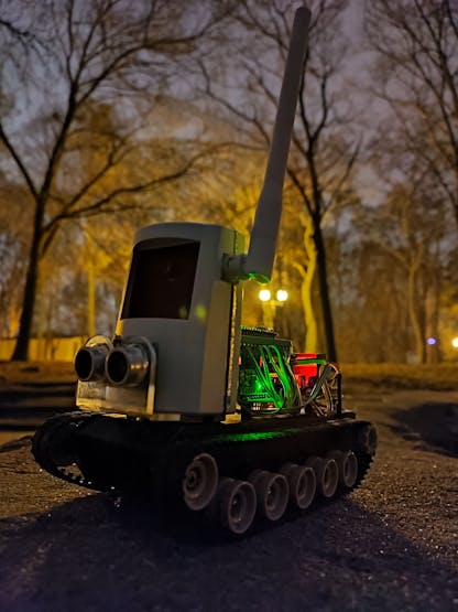
Bonus photo
Conclusions
All source code of Arduino firmware, ESP-32 and Unity application I posted in the repository on GitHub, don't be surprised if you find "interesting solutions". My goal is to show you the principle itself, the best way is to figure it out for yourself and make something of your own based on the knowledge you get.
Writing this article helped me to lay out all the experiences that I had when creating the tank. And to remember the solutions to all those bugs and flaws that arose during the process, which you can avoid and focus finding your own unique bugs to share them with the community. I really hope I can inspire someone to create a cool thing like this.
Schematics
Power network

Wi-Fi tank shematic diagram

Code
Wi-Fi-controlled-tank
Here are full firmware for Arduino and ESP32-Cam and application code on unity


