
Measure angle of your tool
Things used in this project
Hardware components
Story
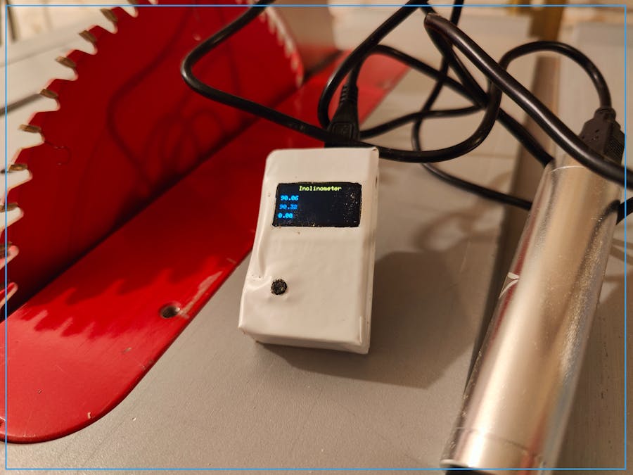
An inclinometer is an instrument used for measuring angles of an object with respect to a base. It is also known as a level gauge or bevel meter. In my case, I need get a very precise angle of the cuttings from my table saw. You can buy a level gauge, or create a simple one by yourself.
https://www.waltswooddesign.com/wp-content/uploads/2022/07/Spresense-Inclinometer.mp4
The Sony Spresense runs on 3v, which saves a lot of battery power, and is fine for the gyroscope + OLED.
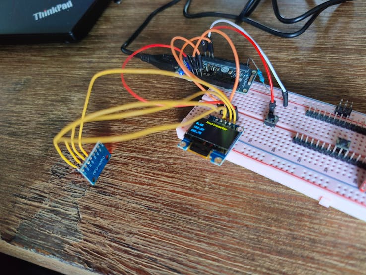
The two devices (gyroscope and display) are communicating using I2C. You can wire them in parallel, to address both at the same time. An additional resistor is not required for the Sony Spresense.
OLED
#include <SPI.h>
#include <Wire.h>
#include <Adafruit_GFX.h>
#include <Adafruit_SSD1306.h>

#define OLED_RESET     -1    // Reset pin # (or -1 if sharing Arduino reset pin)
#define SCREEN_WIDTH   128   // OLED display width, in pixels
#define SCREEN_HEIGHT  64    // OLED display height, in pixels
#define SCREEN_ADDRESS 0x3C  // 0x3D for 128x64, 0x3C for 128x32

Adafruit_SSD1306 display(SCREEN_WIDTH, SCREEN_HEIGHT, &Wire, OLED_RESET);
void initializeDisplay();
void loopDisplay();
void printAngle();

void setup(){
  Serial.begin(9600);
  initializeDisplay();
}

void loop(){
  loopDisplay();
  printAngle();
  delay(10);
}

void initializeDisplay() {
  if(!display.begin(SSD1306_SWITCHCAPVCC, 0x3C)) { // Address 0x3D for 128x64
    Serial.println(F("SSD1306 allocation failed"));
    for(;;);
  } else {
    Serial.println(F("OLED display found"));
  }

  display.clearDisplay();

  display.setTextSize(4);
  display.setTextColor(WHITE);
  display.setCursor(0, 0);
  display.println("Hello, world!");
  display.display();
}

void loopDisplay() {
}
Gyroscope
#include <SPI.h>
#include <Wire.h>

void initializeGyros();
void loopGyros();
const int MPU_addr=0x68;
int16_t AcX,AcY,AcZ,Tmp,GyX,GyY,GyZ;
int minVal=265;
int maxVal=402;
double x;
double y;
double z;

void setup(){
  Serial.begin(9600);
  initializeGyros();
}

void loop(){
  loopGyros();
  delay(10);
}

void initializeGyros() {
  Wire.begin();
  Wire.beginTransmission(MPU_addr);
  Wire.write(0x6B);
  Wire.write(0);
  Wire.endTransmission(true);
}

void loopGyros() {
  Wire.beginTransmission(MPU_addr);
  Wire.write(0x3B);
  Wire.endTransmission(false);
  Wire.requestFrom(MPU_addr,14,true);
  AcX=Wire.read()<<8|Wire.read();
  AcY=Wire.read()<<8|Wire.read();
  AcZ=Wire.read()<<8|Wire.read();
  int xAng = map(AcX,minVal,maxVal,-90,90);
  int yAng = map(AcY,minVal,maxVal,-90,90);
  int zAng = map(AcZ,minVal,maxVal,-90,90);

  x= RAD_TO_DEG * (atan2(-yAng, -zAng)+PI);
  y= RAD_TO_DEG * (atan2(-xAng, -zAng)+PI);
  z= RAD_TO_DEG * (atan2(-yAng, -xAng)+PI);

  Serial.print(x);
  Serial.print(",");
  Serial.print(y);
  Serial.print(",");
  Serial.println(z);

  readings[readIndex] = z;
  readIndex++;
  if (readIndex == numReadings) { readIndex = 0; }
}
Button
The button is used to set the base (default) angle. A simple smooth algorithm is used to flatten the readings.
#define BUTTON_PIN     27    // input for button

const int numReadings  = 20;
double readings [numReadings];
int readIndex  = 0;
double smooth();

void setup(){
  Serial.begin(9600);
  initializeButton();
}

void loop(){
  loopButton();
  printAngle();
  delay(10);
}

void initializeButton() {
  pinMode(BUTTON_PIN, INPUT);
}

void loopButton() {
  bool clicked = digitalRead(BUTTON_PIN);
  if (clicked) {
    offset = smooth();
  }
}

void printAngle() {
  double real = abs(smooth() - offset);
  if (real > 180) { real = real - 180; }
  Serial.println(real);
}

double smooth() {
  double average;
  for (int i = 0; i < numReadings; i++) {
    average += readings[i];
  }
  average = average / numReadings;
  return average;
}
Finalize
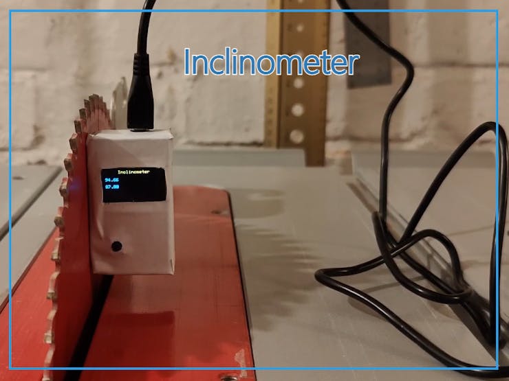
Create a box to fit all components inside and use an USB power station to provide the power.
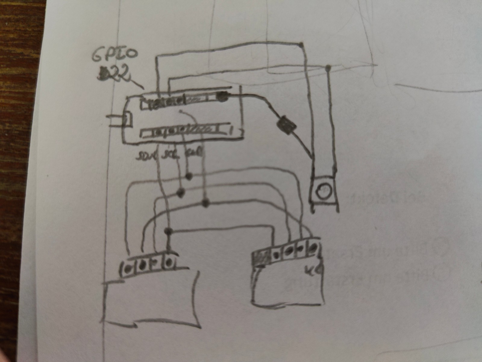
Schematics
Schematics
Code
main.ino
Arduino
#include <SPI.h>
#include <Wire.h>
#include <Adafruit_GFX.h>
#include <Adafruit_SSD1306.h>

#define OLED_RESET     -1    // Reset pin # (or -1 if sharing Arduino reset pin)
#define SCREEN_WIDTH   128   // OLED display width, in pixels
#define SCREEN_HEIGHT  64    // OLED display height, in pixels
#define SCREEN_ADDRESS 0x3C  // 0x3D for 128x64, 0x3C for 128x32
#define BUTTON_PIN     27    // input for button

Adafruit_SSD1306 display(SCREEN_WIDTH, SCREEN_HEIGHT, &Wire, OLED_RESET);
void initializeDisplay();
void loopDisplay();
void printAngle();

void initializeGyros();
void loopGyros();
const int MPU_addr=0x68;
int16_t AcX,AcY,AcZ,Tmp,GyX,GyY,GyZ;
int minVal=265;
int maxVal=402;
double x;
double y;
double z;

void initializeButton();
void loopButton();
double offset = 0;

const int numReadings  = 20;
double readings [numReadings];
int readIndex  = 0;
double smooth();

void setup(){
  Serial.begin(9600);

  initializeButton();
  initializeDisplay();
  initializeGyros();
}

void loop(){
  loopButton();
  loopGyros();
  loopDisplay();
  printAngle();
  delay(10);
}

// >>>>>>>>>>>> Display >>>>>>>>>>>>>>>

void initializeDisplay() {
  if(!display.begin(SSD1306_SWITCHCAPVCC, 0x3C)) { // Address 0x3D for 128x64
    Serial.println(F("SSD1306 allocation failed"));
    for(;;);
  } else {
    Serial.println(F("OLED display found"));
  }

  display.clearDisplay();

  display.setTextSize(4);
  display.setTextColor(WHITE);
  display.setCursor(0, 0);
  display.println("Hello, world!");
  display.display();
}

void loopDisplay() {
}

// <<<<<<<<<<<< Display <<<<<<<<<<<<<<<
// >>>>>>>>>>>> Gyros   >>>>>>>>>>>>>>>

void initializeGyros() {
  Wire.begin();
  Wire.beginTransmission(MPU_addr);
  Wire.write(0x6B);
  Wire.write(0);
  Wire.endTransmission(true);
}

void loopGyros() {
  Wire.beginTransmission(MPU_addr);
  Wire.write(0x3B);
  Wire.endTransmission(false);
  Wire.requestFrom(MPU_addr,14,true);
  AcX=Wire.read()<<8|Wire.read();
  AcY=Wire.read()<<8|Wire.read();
  AcZ=Wire.read()<<8|Wire.read();
  int xAng = map(AcX,minVal,maxVal,-90,90);
  int yAng = map(AcY,minVal,maxVal,-90,90);
  int zAng = map(AcZ,minVal,maxVal,-90,90);

  x= RAD_TO_DEG * (atan2(-yAng, -zAng)+PI);
  y= RAD_TO_DEG * (atan2(-xAng, -zAng)+PI);
  z= RAD_TO_DEG * (atan2(-yAng, -xAng)+PI);

  Serial.print(x);
  Serial.print(",");
  Serial.print(y);
  Serial.print(",");
  Serial.println(z);

  readings[readIndex] = z;
  readIndex++;
  if (readIndex == numReadings) { readIndex = 0; }
}

// <<<<<<<<<<<< Gyros <<<<<<<<<<<<<<<
// >>>>>>>>>>>> Button >>>>>>>>>>>>>>>

void initializeButton() {
  pinMode(BUTTON_PIN, INPUT);
}

void loopButton() {
  bool clicked = digitalRead(BUTTON_PIN);
  if (clicked) {
    offset = smooth();
  }
}

// <<<<<<<<<<<< Button <<<<<<<<<<<<<<<

void printAngle() {
  double real = abs(smooth() - offset);
  if (real > 180) { real = real - 180; }
  display.clearDisplay();
  // display.getInterface().flipHorizontal();
  display.setTextSize(1);
  display.setCursor(29, 0);
  display.println(F("Inclinometer"));
  display.setTextSize(1);
  display.setCursor(0, 16);
  display.println(real);
  display.setCursor(0, 32);
  display.println(z);
  display.setCursor(0, 48);
  display.println(offset);
  display.display();
}

double smooth() {
  double average;
  for (int i = 0; i < numReadings; i++) {
    average += readings[i];
  }
  average = average / numReadings;
  return average;
}
The article was first published in hackster, Jul 28, 2022
cr: https://www.hackster.io/walwode/inclinometer-with-sony-spresense-90e211
author: Walter Heger


