
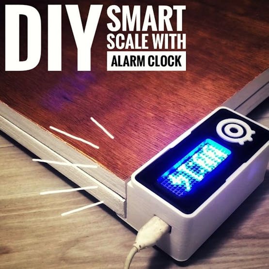
A DIY smart scale with alarm clock. No more snoozing: the alarm will go on until you stand on the scale and give up going back to bed!

Things used in this project
Hardware components
Software apps and online services
Autodesk Fusion 360: https://www.hackster.io/autodesk/products/fusion-360?ref=project-200d98
Adafruit.io
Hand tools and fabrication machines
3D Printer (generic)
Story

In my previous project, I developed a smart bathroom scale with Wi-Fi. It can measure user's weight, display it locally and send it to the cloud. You can get more details about this on link below:
https://www.hackster.io/igorF2/diy-wi-fi-smart-scale-with-esp8266-adafruit-io-and-ifttt-fc68d1
This solved part of my problems: how to keep a record of my weight and track my gain (or loss) of weight. And then I decided to tackle a second problem: how to wake up earlier (and stay awake)!
Smartphones' alarm clocks typically comes with snooze function. With the push of a button there goes another 10 minutes... and since it is impossible to press the snooze button only once, there goes an hour!
So I thought: how do I make sure I get out of bed (and maybe don't come back) after the ringing of my alarm clock? A normal person might think about putting the alarm clock more distant (or to add several alarms), however I preferred to attack the problem in the makerstyle: using a bit of electronics, programming and Wi-Fi!
In this project I turned my smart balance into an alarm clock. Now, in addition to the features already developed, it has an integrated clock (synchronized with an internet server) and a buzzer. Once the alarm is triggered, it continues to ring until the user can gather enough courage to get out of the bed and stand for a few seconds on the scale.
There are several ways to use this tutorial. You can use it to:
Learn how to program an ESP8266 using the Arduino IDE; Practice your 3d printing, electronics, programming, soldering skills, etc; Learn some tricks using an ESP8266 (using displays, a buzzers, etc.); Learn how to use IFTTT and Adafruit.io on your projects; Make some experiments with woodworking; Follow it to the end and create your own gadget!
Liked that project? Please consider supporting my future projects with a small Bit/coin donation! :D BTC Deposit Address: 1FiWFYSjRaL7sLdr5wr6h86QkMA6pQxkXJ
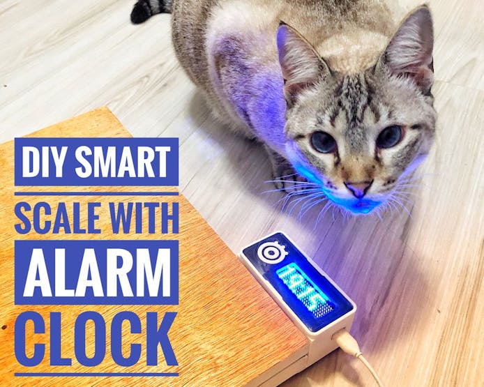
P.s. #1: it's not meant to be used as a cat scale! But, since they were always by my side, they had their place in this tutorial.
P.s. #2: no cats were harmed durring the this project!
Step 1
The following tools and materials were used in this project:
Tools and materials:
3D printer (link). It was used for printing the case where the electronics are encloused. Solder iron and wire. Some of the components (ESP8266 Firebeetle and LED matrix cover, for instance) doesn't come with soldered terminals. I needed to solder some wires or pins in order to connect those devices. Shrinking tube (link / link).l also had to solder the wires of each load cell. A piece of shrinking tube might be used for a better isolation of the conductors. Screwdriver. The structure is mounted using some screws. A set of screwdrivers was used. Screws. I used some screws to attach the 3D printed parts to the base of the scale. M2x6mm Bolts. They were used for mounting the electronics inside the case. 1.75mm PLA (link / link / link) of any color you want. FireBeetle ESP8266 dev board. It's really easy to use and program using Arduino IDE. It has built-in Wi-Fi module, so you can use it in a variaty of projects. It has a connector for a 3.7V battery, which was really usefull for assembling this project. I has also a built-in battery charger. It will recharge the battery when connected to an USB plug. You can also use other ESP8266 based bords (link / link / link) if you wish. Deppending on the board you choose, it would be a little more difficult to connect and recharge the battery, or to connect the LED matrix. The dimensions of the case will also need to be verified. Firebeetle covers - 24x8 LED matrix. This module easilly fits on top of the Firebeetle ESP8266 dev board. I used it to display the values measured by microcontroller, display some status, etc. You can also use other kinds of display if you wish, like ordinary LCD displays (link / link) or OLED displays (link / link). HX711 module (link / link / link). This works as a load cell amplifier. Four strain gauge load cells are connected to this module, and it communicates on a serial communication with the ESP8266 microcontroller. 50kg load cell (x4); (link / link). They are used to measure the weight of the user. Four of them were used for a maximum weight of 200kg. Buzzer (link). This was used for creating annoying noises and wake me up! Micro USB cable; 6 female-female jumper wires (link / link); 2 x 15 mm plywood sheet (30 x 30 cm). It was used for the base of the scale.
The links described above are only a suggestion of where you can find the items used in this tutorial (and support my future hacks). Feel free to search for them elsewhere and buy at your favourite store.
I used a FireBeetle ESP8266 dev board, which was kindly supplied by DFRobot. It worked perfectly!
Did you know you can buy a Anet A8 3D printer for only $139.99? Get yours! http://bit.ly/2kqVOdO
Step 2: 3D Modeling
In this project I used the same 3D printed parts designed for my DIY Wi-Fi Smart Scale project.
The smart scale was desgined using Fusion 360 CAD software. The model is composed of three different 3D printed parts: cover, case and foot.
A 3D printed case provides an enclosure for the electronics, protecting them from physical contact. Electronics are attached in the cover part (using some bolts). This part has a front visor, where the display is attached. Load cells fit into the foot part, which allows the sensors to be attached to the base.
Step 3: 3D Printing and Woodworking
You can download all the stl files on the following websites:
https://www.thingiverse.com/thing:2934791
https://pinshape.com/items/45555-3d-printed-diy-wi-fi-smart-scale
https://www.youmagine.com/designs/diy-wi-fi-smart-scale
https://cults3d.com/en/3d-model/gadget/diy-wi-fi-smart-scale
https://www.myminifactory.com/object/3d-print-diy-wi-fi-smart-scale-66654
I printed the whole structure in PLA, usign two different colors. The whole print took me around 5h30, using 0.2 mm resolution and 10% infill. No supports needed.
This is a experimental prototype. Notice that it was designed for a given ESP8266 dev board model (the ESP8266 Firebeetle).
If you don't have a 3D printer, here are some things you can do:
Ask a friend to print it for you; Find a hacker/maker space nearby. The parts used in this model can be printed quickly. Some hacker/maker spaces will only charge your for the materials used; Buy your own 3D printer. You can find the Creality3D CR10 for only $389.99! Get yours at http://bit.ly/2JIUVrfImprovise! You can try to assemble a structure without 3D printed parts.
The base of my scale was mede of two 15mm 30 x 30 cm sheets of plywood.
I made some whole using a screwdriver for passing the wires of the load cells, and for attaching the 3D printed parts.
Step 4: Assembling the Scale
You can find detailed instructions on how to assemble the scale on my previous tutorial (link). This time I'll focus on the changes I had to make on the hardware and software to add the new features (a internet synced clock with alarm buzzer). I suggest you to read my previous project before moving on, specially if you want to make the complete gadget.
Long story short, I had to do the following:
Solder some components; Fit the load cells inside the 3D printed foot parts and attached them to the first wooden panel using some screws; Attach the display, HX-711 module and ESP8266 Firebeetle to the 3D printed cover part; Use some screws to mount the case to the wooden panel; Connect the wires (more on this later); Close 3D printed case with 3D printed cover Install the second wooden pannel on the top of the first one; Painted the wooden panels and add some details to the case for a better finishing.
Step 5: Preparing the Electronics and Wiring Up the Circuits
At this stage, the scale was already fully assembled and functional. I'll describe here the changes I had to make to add a buzzer.
First I had to disassemble part of the structure. Front cover was removed in order to access microcontroller's pins. A couple of jumpers were connected to digital pins D3 and D5. One of them will provide a GND reference to the buzzer, while the other one will provide frequency signal and create the sounds.
No soldering was required this time. I used female-female jumpers for the connections between the GPIO pins and buzzer pins.
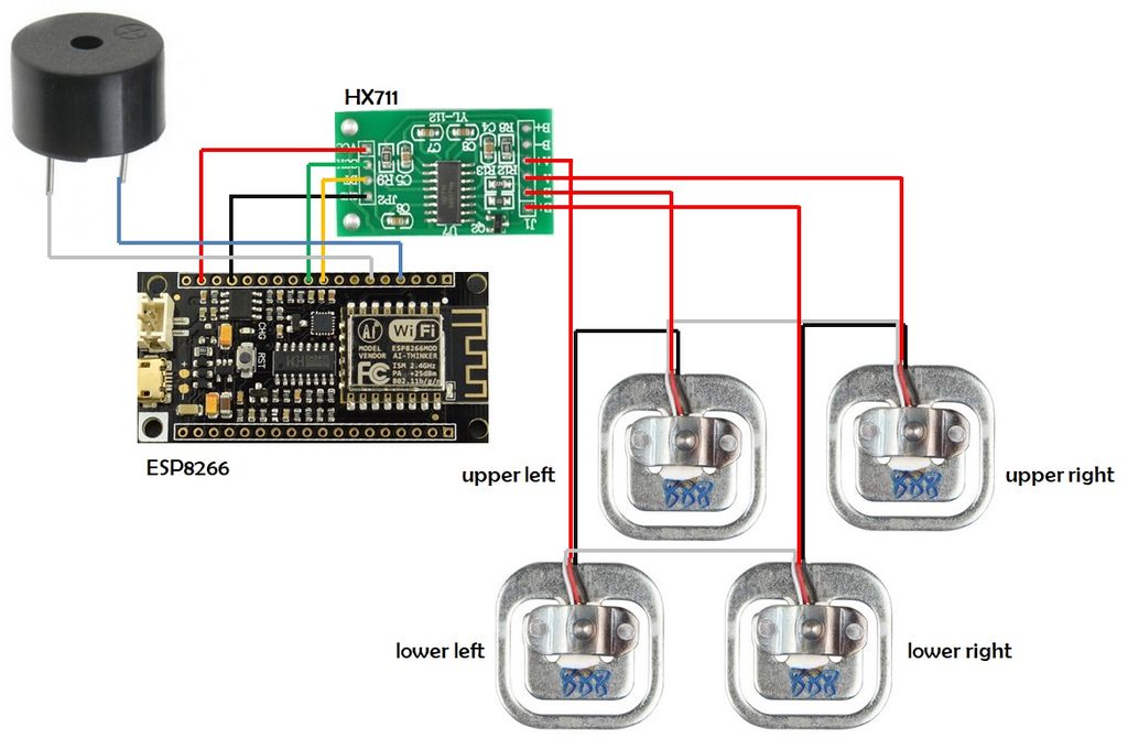
In the end, I had the following connections:
HX711 - input:
Upper left load cell signal (red wire) => HX711 E- pin Lower left load cell signal (red wire) => HX711 A+ pin Upper right load cell signal (red wire) => HX711 A- pin Lower right load cell signal (red wire) => HX711 E+ pin
HX711- output: (used female-female jumper wires)
HX711 Vcc pin => ESP8266 3.3V pin HX711 GND pin => ESP8266 GND pin HX711 SCK pin => ESP8266 GPIO 12 (pin D9) HX711 DT pin => ESP8266 GPIO 0 (pin D8)
Buzzer: (used female-female jumpers)
Buzzer positive pin => ESP8266 GPIO 10 (pin D3) Buzzer negative pin => ESP8266 GPIO 2 (pin D5)
Display module:
Connect it on the top of the Firebeetle ESP8266
Notice I used pin D5 as a GND for my buzzer. Once all the ground pins of my ESP8266 board were already taken, I used this pin as an output, set to LOW, so that it would work as a GND pin. The current consumed by the buzzer is limited, so it's ok.
The sound of this buzzer isn't that loud. After all, it's only a cheap 5V buzzer, powered from a 3.3V pin. But it's certainly enough for waking me up (considering I put it next to my bed).
Once the connections were checked, the case was closed again. Now let's move on to the Arduino code!
Step 6: Setup FireBeetle ESP8266 on Arduino IDE

As before, I used Arduino IDE for programming my ESP8266. It's the easier way if you've already used an Arduino before, and you won't need to learn a new programming language, like Python or Lua for instance.
If you've never done this before, first you'll have to add ESP8266 board support to the Arduino software.
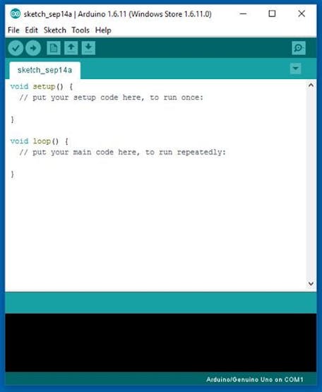
1. Download and install Arduino IDE latest version
You can find the latest version for Windows, Linux or MAC OSX on Arduino's website: https://www.arduino.cc/en/main/software
Download it for free, install it on your computer and launch it.
2. Adding ESP8266 board
Arduino IDE already comes with support to a lot of different boards: Arduino Nano, Mine, Uno, Mega, Yún, etc. Unfortunatly ESP8266 isn't by default among those suported development boards. So in order to upload your codes to a ESP8266 base board, you'll have to add its properties to Arduino's software first.
Navigate to File > Preferences (Ctrl +, on Windows OS); Add the following URL to Additional Boards Manager textbox (the one on the bottom of the Preferences window): https://raw.githubusercontent.com/DFRobot/FireBeetle-ESP8266/master/package_firebeetle8266_index.jsonIf the text box wasn't blank, it means had already add other boards before on Arduino IDE before. Add a comma at the end of the previous URL and the one above. Hit "Ok" button and close the Preferences Window. Navigate for Tools > Board > Boards Manager for adding your adding your Firebeetle ESP8266 board. Type "Firebeetle-ESP8266" on the search text box, select "FireBeetle-ESP8266 by DFRobot" and install it.
Now your Arduino IDE will be ready to work with the Firebeetle ESP8266 development board.
3. Adding the libraries
The following libraries will be used for our Arduino code. Download the following libraries:
Adafruit NeoPixel library (https://github.com/adafruit/Adafruit_NeoPixel) Arduino http client library (https://github.com/arduino-libraries/ArduinoHttpClient) Arduino IO library (https://github.com/adafruit/Adafruit_IO_Arduino) Adafruit MQTT library (https://github.com/adafruit/Adafruit_MQTT_Library) HX711 library (https://github.com/bogde/HX711) Firebeetle LED matrix library (https://github.com/Chocho2017/FireBeetleLEDMatrix)
Navigate to Sketch -> Include Library -> Manage Libraries... on your Arduino IDE and add the libraries above.
Connect the ESP8266 module to your PC's USB port and we are ready for some code!
Step 7: Adafruit.IO Configuration

But first, let's configure our Adafruit.io feed.
There are a lot of datalogging services available for communicating a microcontroller to the web. With those services you can upload/download data to/from the cloud, and do a lot of cool stuff. Take a look on my tutorial on how to use an Arduino + ESP8266 to send data from a mini-weather station for Thinkgspeak for instance.
Adafruit.IO is one of those free services. It's really easy to use and promises to bring internet of things to everyone!
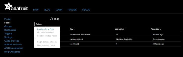
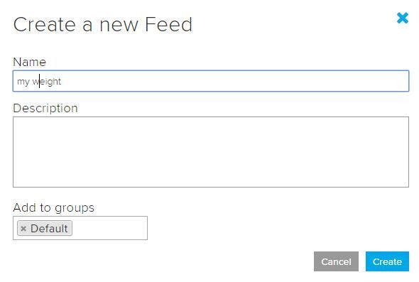
Create Adafruit IO Web Feed
Under Feeds > Create a new Feed add a new feed named "my weight". It will create a database, and we will use it store measured weight received from the gadget.
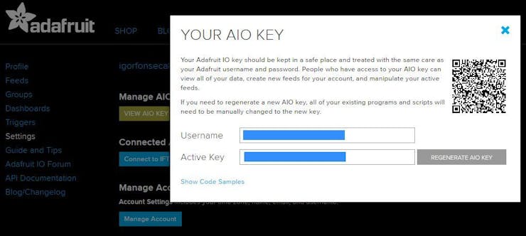
Sign in at https://io.adafruit.com/ Create another feed named "alarm clock". This one was used for the configuration of the alarm clock;Copy your Adafruit.IO key, which will be later used for allowing your device accessing the database. Navigate for Settings > View AIO key and copy the active key code. You'll need it for your Arduino (NodeMCU) code later.
On my previous project (link) I also present how to configure IFTTT service for the communication between Adafruit.io and some fitness tracking plaform (Fitbit, Strava, iOS Health or Misfit). This time I'll focus on the alarm clock part of the code, so I'll skip the details on how to configured IFTTT.
Step 8: ESP8266 Code
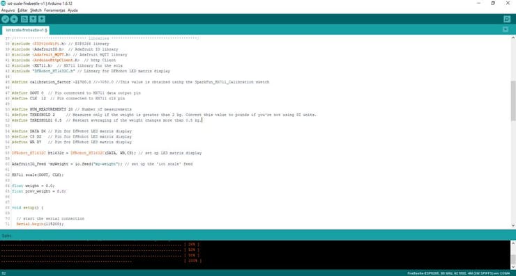
At this point the gadget is almost finished!
Download the Arduino code and open it on the Arduino IDE. The following parameters will have to be updated:
WIFI_PASS: enter your Wi-Fi network password here
IO_KEY: Adafruit.io key should be entered here
TIMEZONE: the time zone you live in (for clock adjustment)
bedtimehour and bedtimeminute: the time you usually go to bed
WIFI_SSID: enter your Wi-Fi router SSID here
IO_USERNAME: this is your Adafruit.io user name
calibration_factor: this constal is used for the calibratiob of the scale
Configure them, and upload the code to the ESP8266. The code will start running immediately.
The smart scale will try to connect the WiFi network and Adafruit.io service. On the first use you'll have to setup the alarm time. Go to https://io.adafruit.com/username/feeds/alarm-clock and click Actions > Add data. Enter the time to be used by the alarm clock (use hh:mm format) and send. This value will be received by the scale and stored in its EEPROM memory.
Every minute the clock will be updated, based on values received from Google server. You can find more details about that on here. If bed time is reached, the display will turn of (but the scale will keep running). On alarm time, buzzer will start ringing until someone (or something) is on the scale.
If the weight measured rises above a given value (THRESHOLD), it will read the weight a given number of times (NUM_MEASUREMENTS) and calculate the average weight. If the weight changes more than a certain value (THRESHOLD1) between two consecutive measures, the process will be restarted. After the average value is determined, it will be displayed on the LED matrix and transmitted to Ardafruit.io. The scale will wait until the user steps out, and restart.
To calibrate the scale, put a know weigth object on the top of the scale, and adjust its factor until it indicates the right value. You can measure your own weight on another scale you trust, them measure your weight again on the IoT scale and adjust the factor accordingly.
Step 9: Usage
Once the scale is powered, it will automatically connect the Wi-Fi router and try to reach Adafruit.io. This way it will be ready to send some data (measured weight) and receive some information (alarm clock trigger time).
Then it will connect Google server and read current time. It will be displayed, and the gadget will periodically sync the time again.
Alarm time is received from Adafruit.io. Whenever the feed is updated, this value will be sent to the scale, and it will store it on it's EEPROM memory. This way, if the connection is lost, or if it's powered down for some reason, it won't lose this information.
When alarm time is reached, the buzzer will start ringing. It will remain that way until someone step on it for weight measurement. This value will be recorded on Adafruit.io.
Display will be turned off at a given time, so that it won't bother you durring bed time. Once the alarm is triggered (in the morning) the display will be on again.
Step 10: Final Considerations
I put a lot of effort into this project, to make it as clear and educational as possible. If you liked it, please don't forget to 'like' and 'share' it. Your support is very important to me! :D
If you still don't follow my tutorials, take a look at those other projects in which I explain a little bit about internet of things, robotics and 3D printing. I hope you enjoy them too!
https://www.hackster.io/igorF2/iot-smart-wallet-with-firebeetle-esp32-and-arduino-ide-4513f9
https://www.hackster.io/igorF2/iot-air-freshener-w-nodemcu-arduino-adafruit-io-ifttt-dcf959
https://www.hackster.io/igorF2/minimalist-iot-clock-using-esp8266-adafruit-io-and-ifttt-65f297
https://www.hackster.io/igorF2/3d-printed-articulating-led-lamp-91df63
https://www.hackster.io/igorF2/nunchuk-controlled-robotic-arm-with-arduino-b1c0fa
Liked any of my projects? Please consider supporting my future projects with a small Bit/coin donation! :D
BTC Deposit Address: 1FiWFYSjRaL7sLdr5wr6h86QkMA6pQxkXJ
Schematics
Code
The article was first published in hackster, August 7, 2018
cr: https://www.hackster.io/igorF2/diy-smart-scale-with-alarm-clock-200d98
author: Igor Fonseca Albuquerque


