
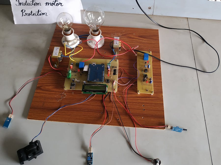
Project to Protect the Single Phase Induction Motor from faults like Over Voltage, Under Voltage, Over Current, Vibrations, Flame, Float.
Things used in this project
Hardware components
Story
ABSTRACT
In this project we give a special idea of industrial automation, and fault monitoring. Induction motors are the nerves of many industries. Hence industrial automation is required for precise and accurate operation. The project Arduino-based parameter monitoring system for induction motor proposes a control and monitoring system for induction motor based on Arduino communication protocol for safe and economic data communication in industrial fields. The current, voltage, and temperature of the induction motors are very important parameters for its control system. The performance of an induction motor is directly affected by these fundamental quantities. However, during continuous operation, it is difficult to control the machines. Arduino system is used for collecting and storing data and generate control signals to start or stop the induction machine. We measure the different types of fault such as Over Voltage, Over Current, and Over Temperature.
Nowadays, the induction motor has remained the most popular type of motor for industrial applications. Monitoring and controlling of induction motor parameters are very essential in many applications and also for reliable operation there are several techniques available for the same. This paper deals with the monitoring of various parameters & control of three-phase induction motor remotely based on the Internet Of Things [IOT]. A module of sensor and transducers monitors the parameters like temperature, current, and voltage of induction motor and send to the processing unit which will display parameter on the server. The system also presents the automatic and manual control methods to stop or start the induction motor to avoid any system failures through the server gateway. The Implementation of this scheme will increase the working efficiency of machines by continuously monitor to avoid breakdowns and also to determine the preventive maintenance.
INTRODUCTION
In an industrial environment the single phase induction motors are being used to drive mechanical system and in many production processes. The performance of the motor directly affects the product quality and quantity hence it is necessary to monitor its performance. Nowadays, the wireless systems are often applied for monitoring and control in many areas such as manufacturing processes, robotics, building automation, and so on. Some implementations of wireless monitoring in industry for robots and manipulation systems are being used. An industrial real-time measurement and monitoring system based on Wi-Fi standard is presented. An increased interest in this standard for building automation has been registered recently.
Remote systems are also suitable for monitoring of various parameters such as humidity, temperature, vibration, current and speed especially for monitoring of electric devices. With the modern developments in wireless technologies and devices, wireless sensor networks become very popular for a variety of practical applications. Wireless devices using standards like Arduino kits are widely used in measurement equipment.
The choice is because of their low energy consumption and capabilities, easy maintenance and data collection etc. Another benefit of this method is that it keeps continuous track of the devices for the change in parameters and displays relevant reading continuously. The high degree of protection can be given by alerting the user by giving suitable message so that the operator can take initiation so as to protect the motor.
Hence the portable device also gives provision to save entire system from various errors or unexpected fault occurring in the system by turning OFF the main supply. Automation is the use of motors, control systems and information technologies to optimize productivity in the production of goods and delivery of services. Automation essentially involves leveraging the power of technology to reduce the dependency on human presence and decision making for any process.
Automation also helps reduce peak hour power consumption by enabling people to turn off appliances. Automation greatly decreases the need for human sensory and mental requirements while increasing the speed and repeatability of the process. Automation includes Home automation, industrial automation etc. Earlier systems were mainly based on the use of telephone lines, such as phone-based system for automation and control system using hardware remote controller and an intelligent system.
OBJECTIVES
In this project the concept of the Internet of Things for monitoring motor system parameters remotely · The project uses the Thigs Speak platform.· Early detection of motor failure.· The system has the specific advantage of less maintenance.
PROBLEM STATEMENT
The main types of external faults experienced by an induction motor are over-loading, single phasing, unbalanced supply voltage, locked rotor, phase reversal, ground faults, and under/over voltage.
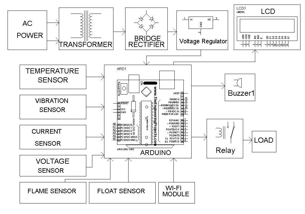
BLOCK DIAGRAM
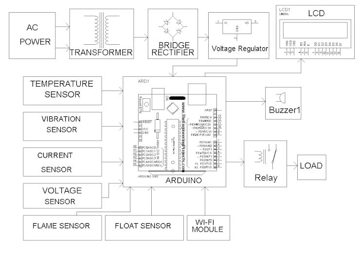
BLOCK DIAGRAM
WORKING PRINCIPLE
8266 wifi module connected to server we can observe all parameters on things speak application or website. This project we are using Things speak app to observe all parameter like temperature, voltage, current, vibration, flame and water level detection.
Whenever it is connected to server there is no limit of distance, we can observe all parameters from any way. After circuit is connected to application all parameters are displayed on LCD.
Relay will be on whenever all paramteres are correct.
Relay will be off whenever temperature increases above 40 degree or current increases above 1A or voltage exceeds 250 or drops below 180.
HARDWARE COMPONENTS
ARDUINO ATMEGALCD DISPLAYCURRENT SENSORRELAYFLOAT SENSORFLAME SENSORDHT11 HUMIDITY SENSORVOLTAGE TRANSFORMERBRIDGE RECTIFIERVOLTAGE REGULATORRESISTORSLEDCAPACITORSPOTENTIOMETERBUZZERVIBRATION SENSOR
SOFTWARE REQUIREMENTS
Arduino IDEThingSpeak Web
CODE
#include <String.h>
#include<LiquidCrystal.h>
LiquidCrystal lcd(4, 5, 6, 7, 8, 9);
#include <SoftwareSerial.h>
SoftwareSerial espSerial = SoftwareSerial(2, 3);
#include "DHT.h" //include DHT library
#define DHTPIN 11 //define as DHTPIN the Pin 3 used to connect the Sensor
#define DHTTYPE DHT11 //define the sensor used(DHT11)
DHT dht(DHTPIN, DHTTYPE);
String apiKey = "MGTA2LIWRLRDSBL1"; // replace with your channel's thingspeak WRITE API key
String ssid = "DEMO"; // Wifi network SSID
String password = "DEMO123456"; // Wifi network password
boolean DEBUG = true;
int buf[10];
int h, t, W, m1, m2;
//int buf[10];
//int h,t,W,m1,m2;
int temperature, humidity, volt, current;
int w = 0;
int s = 0;
int buzzer = 12;
int relay = 10;
const int digitalInPin = A4; //vibrator sensor
int sensorValue = 0;
int voltage = A0; //pot connection
int current1 = A5; //current sensor
int cur = 0, vb = 0 , b = 0;
int v, c, vol, temp;
float s1, s2;
float t1, t2, t3, t4;
//int TempCel;
void setup()
{
Serial.begin(9600);
lcd.begin(16, 2);
lcd.setCursor(0, 0);
lcd.print("WEL COME");
pinMode(buzzer, OUTPUT);
digitalWrite(buzzer, LOW);
dht.begin();
pinMode(relay, OUTPUT);
digitalWrite(relay, HIGH);
delay (1000);
lcd.clear();
lcd.setCursor(0, 0);
lcd.print("CONNECTING WI-FI");
delay (500);
//lcd.clear();
espSerial.begin(9600); // enable software serial
espSerial.println("AT+CWMODE=1"); // set esp8266 as client
showResponse(3000);
espSerial.println("AT+CWJAP=\"" + ssid + "\",\"" + password + "\""); // set your home router SSID and password
showResponse(8000);
lcd.clear();
lcd.setCursor(0, 0);
lcd.print("WI-FI CONNECTED");
delay(500);
if (DEBUG) Serial.println("Setup completed");
lcd.clear();
}
void showResponse(int waitTime)
{
long t = millis();
char c;
while (t + waitTime > millis())
{
if (espSerial.available())
{
c = espSerial.read();
if (DEBUG) Serial.print(c);
}
}
}
boolean thingSpeakWrite(int value1, int value2, int value3, int value4)
{
String cmd = "AT+CIPSTART=\"TCP\",\""; // TCP connection
cmd += "184.106.153.149"; // api.thingspeak.com
cmd += "\",80";
espSerial.println(cmd);
if (DEBUG) Serial.println(cmd);
if (espSerial.find("Error")) {
if (DEBUG) Serial.println("AT+CIPSTART error");
return false;
}
String getStr = "GET /update?api_key="; // prepare GET string
getStr += apiKey;
getStr += "&field1=";
getStr += String(value1);
getStr += "&field2=";
getStr += String(value3);
getStr += "&field3=";
getStr += String(value2);
getStr += "&field4=";
getStr += String(value4);
/*getStr += String(value6);
getStr +="&field7=";
getStr += String(value7);
getStr +="&field8=";
getStr += String(value8);*/
getStr += "\r\n\r\n";
// send data length
cmd = "AT+CIPSEND=";
cmd += String(getStr.length());
espSerial.println(cmd);
if (DEBUG) Serial.println(cmd);
delay(100);
espSerial.print(getStr);
if (espSerial.find(">")) {
// espSerial.print(getStr);
Serial.print(">>>>>>>>>>>>");
if (DEBUG) Serial.print(getStr);
}
else {
espSerial.println("AT+CIPCLOSE");
// alert user
if (DEBUG) Serial.println("AT+CIPCLOSE");
return false;
}
return true;
}
void data()
{
if (isnan(t1) || isnan(t2) || isnan(t3) || isnan(t4))
{
if (DEBUG) Serial.println("Failed to read from sensor");
thingSpeakWrite(t1, t2, t3, t4);
}
else
{
if (DEBUG) Serial.println("S1=" + String(t1) + "");
if (DEBUG) Serial.println("S2=" + String( t3) + "");
if (DEBUG) Serial.println("S3=" + String( t2) + "");
if (DEBUG) Serial.println("S4=" + String(t4) + "");
// if (DEBUG) Serial.println("S2="+String(myBPM)+"");
//if (DEBUG) Serial.println("S3="+String(ldr)+"");
//if (DEBUG) Serial.println("S3="+String(m1)+"");
//if (DEBUG) Serial.println("S3="+String(m2)+"");
Serial.println("thingsspeak write");
thingSpeakWrite(t1, t2, t3, t4); // Write values to thingspeak
}
// thingspeak needs 15 sec delay between updates,
delay(1600);
}
void loop()
//=====FIRST WHILE=========//
{
b = 0;
//======
//  Reading sensors data
//====
h = dht.readHumidity();
t = dht.readTemperature();
volt = analogRead(voltage);
s1 = (volt / 3.788);
current = analogRead(current1);
s2 = (current / 544.35);
sensorValue = digitalRead(digitalInPin);
//========================================
// Displaying all data on LCD and blynk
//========================================
lcd.setCursor(0, 0); lcd.print("T:"); lcd.setCursor(2, 0); lcd.print(t);
lcd.setCursor(5, 0); lcd.print("C:"); lcd.setCursor(7, 0); lcd.print(s2);
lcd.setCursor(11, 0); lcd.print("V:"); lcd.setCursor(13, 0); lcd.print(s1);
//lcd.setCursor(0,1); lcd.print("C:"); lcd.setCursor(3,1); lcd.print(s2);
//lcd.print("--");
delay(2000);
t1 = t;
t2 = s1;
t3 = s2;
t4 = sensorValue;
//========================================
// Action
//========================================
if (sensorValue == HIGH )
{
lcd.setCursor(0, 1);
lcd.print("VIB:1");
v = 1;
b = 1;
}
else
{
lcd.setCursor(0, 1);
lcd.print("VIB:0");
v = 0;
}
if (t > 35)
{
lcd.setCursor(6, 1);
lcd.print("OT");
temp = 1;
b = 1;
}
else
{
lcd.setCursor(6, 1);
lcd.print("NT");
temp = 0;
}
if (s1 >= 250)
{
lcd.setCursor(9, 1);
lcd.print("OV");
vol = 1;
b = 1;
}
else if (s1 <= 180)
{
lcd.setCursor(9, 1);
lcd.print("UV");
vol = 1;
b = 1;
}
else
{
lcd.setCursor(9, 1);
lcd.print("NV");
vol = 0;
}
if (s2 > 1 || cur == 1)
{
lcd.setCursor(13, 1);
lcd.print("OC");
digitalWrite(relay, LOW);
b = 1;
c = 1;
cur = 1;
}
else
{
lcd.setCursor(13, 1);
lcd.print("NC");
c = 0;
}
if (b == 1)
{
digitalWrite(buzzer, HIGH);
}
else
{
digitalWrite(buzzer, LOW);
}
t1 = t;
t2 = s1;
t3 = s2;
t4 = sensorValue;
w++;
if (w > 8)
{
lcd.clear();
lcd.setCursor(0, 0);
lcd.print("Uploading.....");
data();
delay(2000);
w = 0;
lcd.clear();
}
}
RESULT
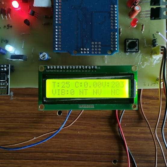
Result
LCD Displaying the Normal conditions on the Motor. Here Temperature is about 25* Celsius, Current is 0.00, Voltage is about 203V, Vibrations are zero and motor is in Normal Voltage, Current and Temperature Condition.
DISCUSSION
Fault Detection in Induction Motor for various parameters like Voltage, Current, Temperature, Float, Flame, Vibration etc using Arduino and Sensors which is interphase with the Things Speak Web through Wifi Module. So we can get resultant output on LCD and the Things Speak Wesite.
ADVANTAGES
· Induction motors are simple and rugged in construction....· Induction motors are cheaper in cost due to the absence of brushes, commentators, and slip rings.· They are maintenance free motors unlike dc motors and synchronous motors due to the absence of brushes, commutated’ s and slip rings.
DISADVANTAGES
· A single phase induction motor, unlike a 3 phase induction motor, does not have a self-starting torque....· During light load conditions, the power factor of the motor drops to a very low value.· Speed control of an induction motor is very difficult to attain.
CONCLUSION
A portable monitoring and controlling unit for electrical motor is implemented using Arduino controller. The unit makes use of ESP 8266 wireless module for transfers of data from Arduino to remote monitoring unit like Mobile phone. Various parameters like voltage, current, temperature and speed of the induction motor are displayed in remote unit. The abnormalities in the system can be easily be identified by the user and controlling of motor from remote unit is verified and found working satisfactorily. Hand held unit makes use of Things speak app and provide graphical view and tabular view of data. This concept uses low cost electronic components and hence affordable. This will help the operator and maintenance peoples to diagnose the failure or causes very easily. The interactive message and display on the screen encourage the operator to initiate innovative operational practices or intelligent mode of operation of motor to conserve energy and life of motors. To control more motors the unit need similar added hardware and networking.
FUTURE SCOPE
In the future lot of scope is there for IoT applications. Worldwide wide all overuse the IoT application for human life sophisticated. In 2025 millions of things connect to the cloud. A lot of research also done on IoT and it's more uses for human life's easiest purpose. Some research works on defense services for security and surveillance, some on automatic vehicle control and traffic signal control, some on the medical field for body control and health care, some on electronic devices, smart home, etc.
Schematics
BLOCK DIAGRAM OF PROJECT
project block diagram
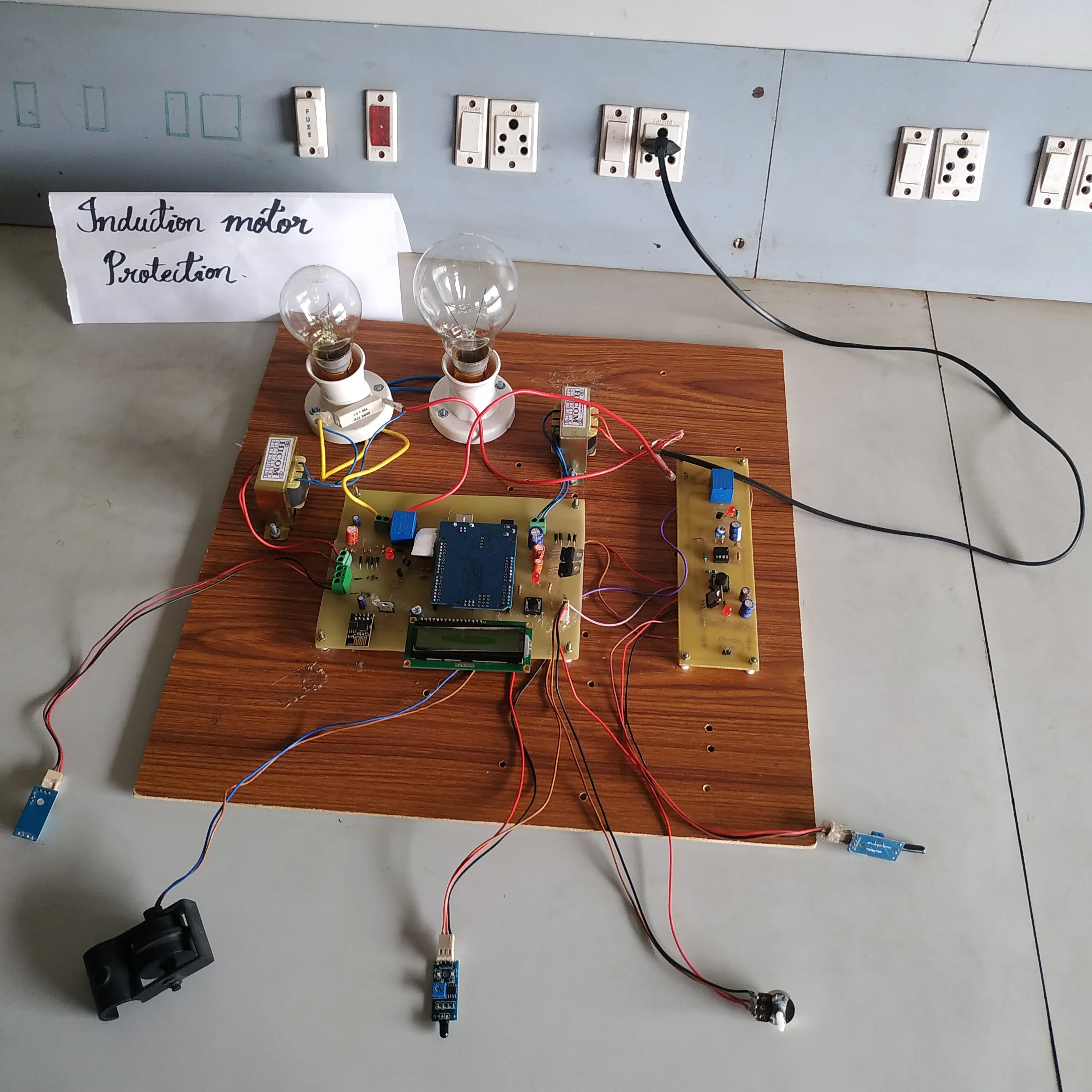
Project Kit
The article was first published in hackster, September 10, 2022
cr: https://www.hackster.io/kykhaveri/induction-motor-protection-0e862d
author: Khudabaksh•yk _6


