
The hydroMazing system manages your growing environment by making localized data-driven decisions so that you don't have to worry.

Things used in this project
Hardware components
Hand tools and fabrication machines
Soldering iron (generic)
Story
It wasn’t my intention to make a product. I simply wanted to solve a common problem. I want to grow plants indoors or under controlled conditions. How can I create an optimum environment for plants to thrive using commonly available electronics and household items? Which is best, soil or hydroponics?
hydroMazing is a tool for making it easier to provide optimum growing conditions for successfully growing plants at home. An independent data collection system and web interface located on your own device not a remote cloud.
~
Learning how to grow plants can be complicated and costly. Plants are resilient, but just one innocent oversight can ruin your crop. You can avoid these costly mistakes by letting a smart gardening system do the hard work for you!
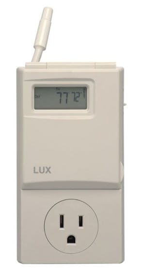
Lux Thermostat
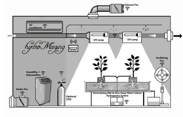
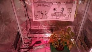
Typical Grow Environment and hydroMazing
It was two years ago when I decided to try using an Arduino Uno microcontroller to replace my individual Lux WIN100 Heating & Cooling Programmable Outlet Thermostat. These outlets control an appliance, such as a small heater or, in this case, a ventilation fan. A device that is plugged into the outlet turns on and off the appliance by using temperature settings that you manually program into each device. This technique for controlling the ventilation fans is effective, yet uses several extension cords. The temperature outlet controllers use old-fashioned relays to switch the state of the device. My initial attempt was to hack an extension box inserting my own relays into it and connecting them to the Arduino Uno. It wasn’t very long before there was a mess of wires with lots of connector nuts and I was left feeling discouraged.
Home Automation

Me, trying to figure out why the demo isn't working :-)


A home automation idea that I had bouncing around in my head for a while was to use wirelessly controlled AC outlets that use a hand-held remote-control. Hacking the remote control to send the signal for the ON or OFF button selected by a corresponding pin on the Arduino Uno shouldn’t be too difficult, right? The nagging concern that was preventing me from testing this idea was the fear that the signal would not be reliable and the Uno might “think” it had turned on a device when it actually failed. Eventually, I was able to convince myself that the best way to find out is to just try and see what happens. Unfortunately, the results of this test wasn’t much better than the relay attempt.
A search on the web for nearly any sensor or electronic doo-dad with “Arduino” will result in a number of products being sold for a few bucks. In this case, I found the 315Mhz and 433Mhz transmitter and receiver pairs that are within the frequency range of most commercial wirelessly controlled outlets. The greatest advantage to using the Arduino family of microcontrollers for these types of projects, is that you can find open-source software to get started. Another search on the web for an “Arduino library” and in this case, transmitter and receiver or tx/rx pair. Now, it was getting exciting for me. I could read the codes coming out of the remote-control, record them, and then program the Arduino to control the corresponding outlets. Designing the software to operate on the Arduino Uno became the challenge. The examples that come with the Arduino software and the examples included with libraries are an excellent start to a project. In my experience, once you start combining and making modifications to the examples it doesn’t take very long before you hit a wall. I don’t think I’m a good programmer, I think I’m a stubborn perfectionist.
In one of my favorite books, Zen and the Art of Motorcycle Maintenance the author, Robert Pirsig, speaks of the gumption trap. Essentially, the gumption trap is an event or mindset that can cause a person to lose enthusiasm and become discouraged from starting or continuing a project. Knowing when to push through the discomfort and frustration and when to take a break and walk-away from the project are personal challenges. There have been times when if I had taken a break, I might not have come-up with an excellent solution to a conflict in my source code. Contrary, there have been times when I have walked-away for a month and worked on a completely different type of project feeling reinvigorated. Perhaps, if the project is important enough, we will be compelled to return to work on it. The trap is convincing ourselves that the project isn’t worth returning to even when it could be amazing. Maybe it really isn’t worth returning to complete and this is where many projects end.
Programming
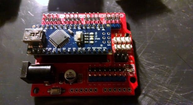
Arduino Nano on Expansion Board
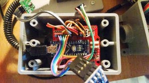
hydroMazing with the lid off
The software I have developed has been programmed into the microcontroller and features a set of base parameters for timing, managing, transmitting, and receiving “sensor” objects and “appliance” objects. Control of appliances is achieved through a set of algorithms I have named “TheDecider, ” which makes decisions based on sensor readings and pre-programmed thresholds and prompts the microcontroller to turn on or off the wirelessly controlled outlets. I wanted the system to be easily modified to work with other environments including aquaponics, growing mushrooms, and anything where control is achieved by reading sensors and operating appliances based on programmed rules. The wirelessly controlled outlets proved to be a reliable method of controlling the fans using the Arduino to send the signals depending on the temperature sensor’s readings. It didn’t take long for the source-code to evolve into a beast. The Arduino family of microcontrollers is limited in how many instructions it can run and hitting the program size limit doesn’t take very long when you want to control more than a few blinking LEDs. I have found that the size limitation has forced me to write better, more efficient code than I initially do. Even with creative variable handling and custom libraries, eventually, there is a need for another microcontroller or to move to a larger one.
Wireless Monitoring w/o Internet
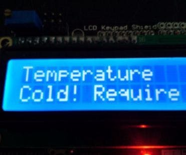
hydroMazing Alert
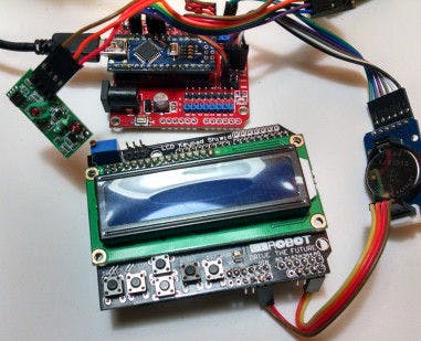
hydroMazing Monitoring Unit
There are several ways that the microcontrollers can communicate with each other. The least expensive wireless method I could find is the nRF24L01 wireless radio transceiver. The module is a low-power, lightweight variety of bluetooth giving hydroMazing the ability to communicate with a monitoring unit.
I decided to add another Arduino Uno with an Liquid Crystal Display shield so that I could display what the sensors were reading, the state of appliances, and alerts with notifications.
I made my own open and adaptable platform that can be custom tailored to a wide variety of gardening needs and conditions; yet, also a self-contained wireless system. The open-architecture of the system allows for ease of integrating Internet connectivity and web services.
Internet Monitoring
generic picture of Raspberry Pi B+
Enter the Raspberry Pi connected with an nRF24L01 module.
I was able to modify much of my Arduino Source code to listen for incoming transmissions and then write that data out to a few files. First, a log file that captures all communications between the Pi and the hydroMazing Monitor. Next, I have the program write out the current state of all sensor objects and a file for all of the appliance objects. When an alert occurs the program will create a file containing that alert. I then added a PHP script to read in the data object’s from their respective files and display live on the Pi’s Apache server.
Next, I wrote a Python script to read the directory for the alerts file and if it exists, read the file, parse out the pertinent information and then email or through SMS text the user. In addition to sending an email or text alert, the python script moves the alert file into position for the PHP script to read and display. Using the log files that are created, I am able to import the data into a database. Once the hydroMazing’s data is recorded into a database residing on the Raspberry Pi we can start performing analytics and generate some reports. Monitoring and controlling the system is mostly done for us, but when the hydroMazing needs to alert us to a problem it can now by using the Raspberry Pi.
The hydroMazing Garden Wizard that guides you through your entire grow! The system provides feedback and tips for how to manage the issues that hydroMazing identifies. http://www.hydroMazing.com
Nutrient Solution Monitoring
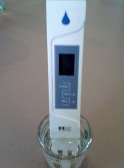
Electroconductivity Probe
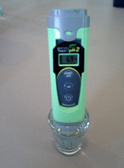
pH probe

The nutrient solution level of the hydroponics container system must be monitored.
As the nutrient solution level decreases it needs to be replenished with fresh water, otherwise the nutrient solution becomes more concentrated and some plants won’t respond well. The hydroMazing Nutrient Controller can activate a pump that adds fresh water to bring the concentration back to the level it was when started, often referred to as “topping-off.” The hydroMazing Nutrient Controller will also monitor your pH and EC, activating pumps to manage the solution, and notifying you when you need to make changes.
hydroMazing Completed
hydroMazing set and the demo tent at the Portland Mini Maker Faire, September, 2016.
hydroMazing Smart Garden System
Want More?
Existential Crisis - Arduino Role-Playing Game SimulatorWhy DIY when you could buy?What is a “Smart” Garden?Starting a Smart Indoor GardenDigging Deeper into Indoor GardeningIndoor Gardening: What can go wrong?Managing Nutrient Solution SystemsWhy Arduino when you can Pi?
Schematics
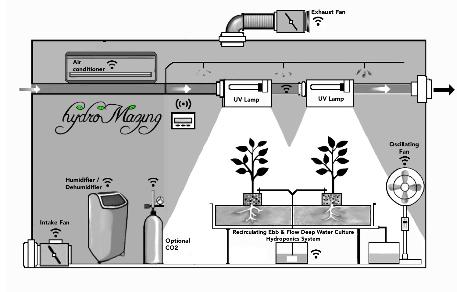
Typical Growroom Environment
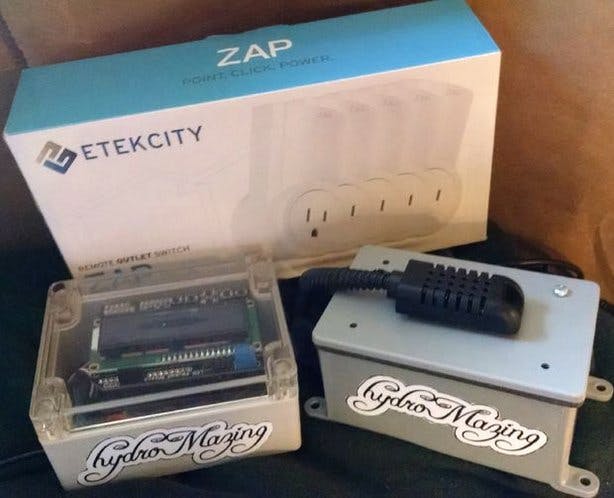
Intake and exhaust fans, grow lights, heaters, dehumidifiers, and pumps automatically controlled via wireless AC outlets
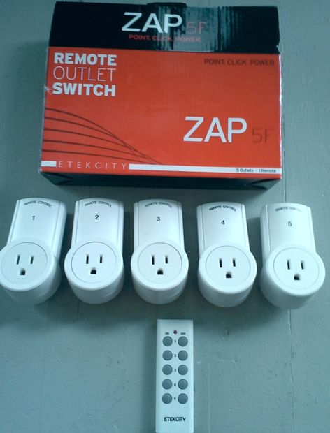
common wirelessly controlled AC outlets
common wirelessly controlled AC outlets used in this project.
hydroMazing Garden Controller and Monitoring System
Assembled and testing
.jpg)
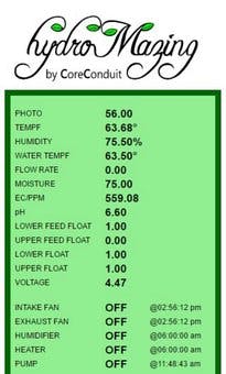
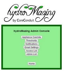
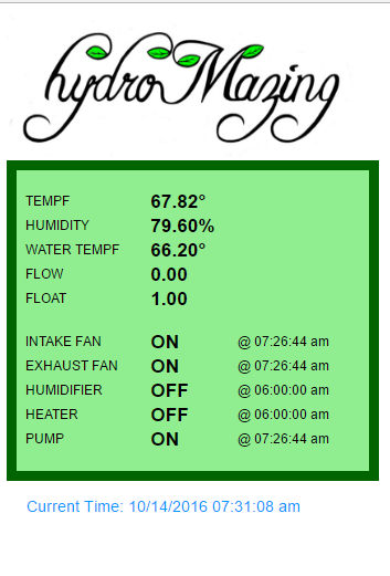
hydroMazing prototype Web Interface
hydroMazing prototype Web Interface
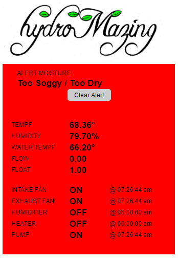
hydroMazing Alert Notification
hydroMazing prototype web Interface for alert notifications.
Code
Settings of objects
C/C++
The CoreSettings.h file contains many critical settings including the nRF network, the AC outlet remote switch codes, the Timer, Appliance, and Sensor object definitions used by the hydroMazing system.
/*
* @file CoreSettings.h
* Copyright (C) 2015 Cory J. Potter - All Rights Reserved
* You may use, distribute and modify this code under the
* terms of the LICENSE.txt
* NOT INTENDED FOR COMMERCIAL USE!
* You should have received a copy of the LICENSE.txt with
* this file. If not, please write to: <[email protected]>
*/

#ifndef __CORESETTINGS_H__
#define __CORESETTINGS_H__

#ifdef ARDUINO

// RX_PIN 3 in use by Dallas Temperature Probe
#define RX_PIN 103
#define TONE_PIN 104
#define TX_PIN 8

// What is our address 1 or 2
uint8_t node_address = 1;
uint8_t totalNodes = 3;
unsigned long lastRxTimeStamp = 0;

const uint64_t nRFbaseAddress = 1034834473100;
uint8_t nRFaddress = 0; // 00 - 255

// NOTE: the "LL" at the end of the constant is "LongLong" type
// 1034834473185, 1034834473170
// const uint64_t tx_pipes[5] = { 0xF0F0F0F0E1LL, 0xF0F0F0F0D2LL, 0xF0F0F0F141LL, 0xF0F0F0F1B0LL, 0xF0F0F0F1BBLL };
// const uint64_t rx_pipes[5] =  { 0xF0F0F0F22ALL, 0xF0F0F0F299LL, 0xF0F0F0F308LL, 0xF0F0F0F377LL, 0xF0F0F0F3E6LL };

// uint64_t tx_pipes[3] = { 0xF0F0F0F0E8LL, 0xF0F0F0F0E7LL, 0xF0F0F0F0E6LL };
// uint64_t rx_pipes[3] =  {0xF0F0F0F0E1LL, 0xF0F0F0F0E2LL, 0xF0F0F0F0E3LL };

uint64_t tx_pipes[3] =  { 0xF0F0F0F0F8LL, 0xF0F0F0F0F7LL, 0xF0F0F0F0F6LL };
uint64_t rx_pipes[3] =  { 0xF0F0F0F0F1LL, 0xF0F0F0F0F2LL, 0xF0F0F0F0F3LL };

/************************************************************************/
// Wirelessly Controlled Outlet Switches
/************************************************************************/
// ETEKCITY #1401
// unsigned long mySwitchOn[] = { 24, 1398067,1398211,1398531 };
// unsigned long mySwitchOff[] = { 24, 1398076,1398220,1398540 };
// ETEKCITY #1405
// unsigned long mySwitchOn[] = { 24,1135923,1136067,1136387 };
// unsigned long mySwitchOff[] = { 24,1135932,1136076,1136396 };
// ETEKCITY #1406
// unsigned long mySwitchOn[] = { 24,4281651,4281795,4282115 };
// unsigned long mySwitchOff[] = { 24,4281660,4281804,4282124 };
// ETEKCITY #1407
// unsigned long mySwitchOn[] = { 24,87347,87491,87811 };
// unsigned long mySwitchOff[] = { 24,87356,87500,87820 };
// ETEKCITY #1411
// unsigned long mySwitchOn[] = { 24,283955,284099,284419 };
// unsigned long mySwitchOff[] = { 24,283964,284108,284428 };
// ETEKCITY #1415
// unsigned long mySwitchOn[] = { 24,21811,21955,22275,23811,29955 };
// unsigned long mySwitchOff[] = { 24,21820,21964,22284,23820,29964 };
// ETEKCITY #1419
// unsigned long mySwitchOn[] = {24,333107,333251,333571,335107,341251};
// unsigned long mySwitchOff[] = {24,333116,333260,333580,335116,341260};
// ETEKCITY #0319
uint8_t totalSwitches = 5;
unsigned long mySwitchOn[] = {24,333107,333251,333571,335107,341251};
unsigned long mySwitchOff[] = {24,333116,333260,333580,335116,341260};

/************************************************************************/
/*	I2C Communications                                                  */
/************************************************************************/
const int MY_ADDRESS = 42;
const int SEND_TO_ADDRESS = 22;
/************************************************************************/
/*  Timers			                                            		*/
/************************************************************************/
//Timer Object = { (type), (interval in millis), ready, triggered, timestamp, (pointer to next object)
Timer Timer_txData 			= { TIMER_TX_DATA, 30000UL, true, false, 0, NULL };
// Timer Timer_Lcd 			= { TIMER_LCD, 12000UL, true, false, 0, &Timer_Log };
// Timer Timer_Lcd_Cycle 		= {	TIMER_LCD_CYCLE, 6000UL, true, false, 0, &Timer_Lcd };
// Timer Timer_Lcd_Scroller 	= { TIMER_LCD_SCROLLER, 500UL, true, false, 0, &Timer_Lcd_Cycle };
//Timer Timer_Ping			= { TIMER_SENSOR_READINGS, 10UL, true, false, 0, &Timer_Log };
//Timer Timer_Lite			= { TIMER_LITE, 180000UL, true, false, 0, &Timer_Ping };
Timer Timer_Save_Settings 	= {	TIMER_SAVE_SETTINGS, 3600000UL, true, false,  0, &Timer_txData };
//Timer Timer_Sensor_Read		= { TIMER_SENSOR_READINGS, 7000UL, true, false,  0, &Timer_Save_Settings };
//Timer Timer_Alerts			= { TIMER_ALERTS, 45000UL, true, false,  0, &Timer_Sensor_Read };
Timer Timer_rxData			= { TIMER_RX_DATA, 6000UL, true, false, 0, &Timer_Save_Settings };

/************************************************************************/
//  Initialize Appliances
/************************************************************************/
Appliance Appliance_Light_1		= {101, 1, APPLIANCE_LIGHT, DEFAULT_TIME, true, false, OFF, NULL };
// Appliance Appliance_Light_2		= {102, 0, APPLIANCE_LIGHT, DEFAULT_TIME, true, false, OFF, &Appliance_Light_1 };
// Appliance Appliance_Light_3		= {103, 0, APPLIANCE_LIGHT, DEFAULT_TIME, true, false, OFF, &Appliance_Light_2 };
Appliance Appliance_IntakeFan   = {104, 1, APPLIANCE_INTAKE_FAN, DEFAULT_TIME, true, false, OFF, &Appliance_Light_1 };
Appliance Appliance_ExhaustFan  = {103, 1, APPLIANCE_EXHAUST_FAN, DEFAULT_TIME, true, false, OFF, &Appliance_IntakeFan };
Appliance Appliance_Humidifier  = {102, 0, APPLIANCE_HUMIDIFIER, DEFAULT_TIME, true, false, OFF, &Appliance_ExhaustFan };
Appliance Appliance_Heater		= {101, 0, APPLIANCE_HEATER, DEFAULT_TIME, true, false, OFF, &Appliance_Humidifier };
//Appliance Appliance_AirPump		= {PIN4, 2, APPLIANCE_PUMP, DEFAULT_TIME, true, false, OFF,  &Appliance_Heater };
Appliance Appliance_FeedPump	= {105, 1, APPLIANCE_PUMP, DEFAULT_TIME, true, false, OFF,  &Appliance_Heater };
uint8_t totalAppliances = 6;

/************************************************************************/
// Initialize Sensors
/************************************************************************/
//Sensor: = { pin; node_address; SENSOR_TYPE; freq; minVal; maxVal; UL timestamp; float value; struct Sensor *next; }
// NULL for the first - We cannot point to an object hasn't been created yet.
Sensor Sensor_Photocell		= { PIN_A0, 1, SENSOR_PHOTO, 100, 50, 100, 0, 25, NULL };
Sensor Sensor_Temp			= { PIN7, 1, SENSOR_TEMPF, 50, 70, 80, 0, 75, &Sensor_Photocell };
Sensor Sensor_Humidity		= {PIN7, 1, SENSOR_HUMIDITY, 50, 40, 70, 0, 50, &Sensor_Temp };
Sensor Sensor_WaterTemp		= {PIN3_INT1, 1, SENSOR_WATER_TEMPF, 100, 50, 70, 0, 65, &Sensor_Humidity };
Sensor Sensor_Flow			= {PIN2_INT0, 2, SENSOR_FLOW, 100, 50, 50, 0, 75, &Sensor_WaterTemp };
//Sensor Sensor_Microphone	= {PIN_A1, 0, SENSOR_SOUND, 60, 10, 100, 0, 75, &Sensor_Flow };
//Sensor Sensor_Ultrasonic	= {PIN_A2, 0, SENSOR_ULTRASONIC, 60, 10, 100, 0, 75, &Sensor_Microphone };
//Sensor Sensor_PIR			= {PIN_A2, 0, SENSOR_PHOTO, 60, 10, 100, 0, 75, &Sensor_Microphone };
//Sensor Sensor_Moisture	= {PIN_A2, 0, SENSOR_MOISTURE, 60, 10, 100, 0, 75, &Sensor_Flow };
Sensor Sensor_Float			= {PIN_A2, 1, SENSOR_FLOAT, 100, 0, 1, 0, 1, &Sensor_Flow };
Sensor Sensor_Voltage		= {PIN1_TX, 1, SENSOR_VOLTAGE, 100, 0, 100, 0, 50, &Sensor_Float };
uint8_t totalSensors = 7;

/************************************************************************/
The article was first published in hackster, December 27, 2015
cr: https://www.hackster.io/bitsandbots/the-hydromazing-smart-garden-system-a802e5
author: rajeshjiet


