
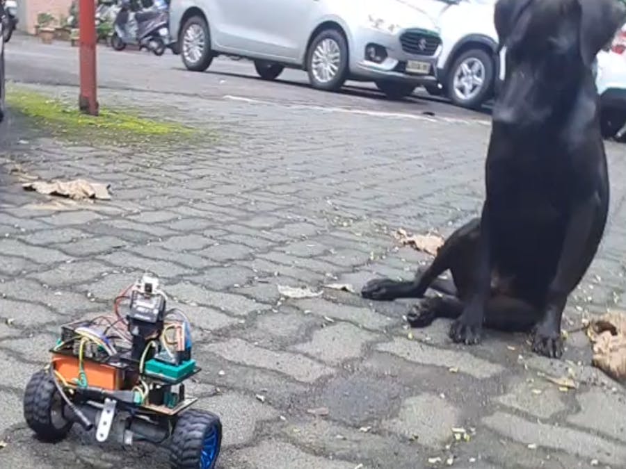
This self balancing mobile robot with pan & tilt camera can be navigated remotely from host PC without the need to be in line of sight.
Things used in this project
Hardware components
Software apps and online services
Computer Aided Simulation Program (CASP)
Story
Self-balancing mobile robots (SBMRs) are unique among others, just because of their ability to balance on a given fixed position. A typical SBMR measures inclination angle with the combination of accelerometer and gyroscope measurements and corrects itself by moving forward or backward to make the angle zero. Proportional-Integral-Derivative (PID) controller is used for deciding how much movement is required and at what rate to quickly correct the angle drift and stabilize the robot. Things become challenging when such a robot is to be navigated (moved or rotated) manually from remote location.
This project demonstrates how to build a basic WiFi remote controlled 2 wheeled SBMR that has an on-board WiFi camera mounted on a servos powered pan & tilt assembly. It is manually controlled by the user from host PC through WiFi. Because of the live video feed available from the on-board camera, the SBMR need not be inline of sight from the user.
Getting Started
Step 1: Build the hardware as described in the ‘Hardware Development’ section.
Step 2: Install latest version of CASP from this link: https://aadhuniklabs.com/?page_id=550. Please go through this link: https://aadhuniklabs.com/?page_id=554 for video tutorials on CASP. Please note that CASP version 0.9.5.3 dated 19.09.2022 and above is required for this project.
Step 3: Download example project on ‘Self Balancing Remote Controlled Mobile Robot with On-board Camera’ at this link: https://aadhuniklabs.com/casp-examples/#robotics and follow the steps mentioned in the ‘Software Development’ section.
Step 4: Some adjustments as described in ‘Adjustments’ section are required for tuning the software to match your developed hardware. You may also further enhance the performance of the robot by modifying the source code from the custom blocks.
Step 5: Finally, keyboard and mouse controls to control the SBMR are described in ‘Control Methodology’ section.
Please write to us at https://aadhuniklabs.com/contact for any queries & suggestions related to this project.
Hardware Development
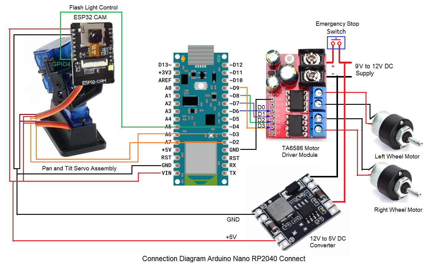
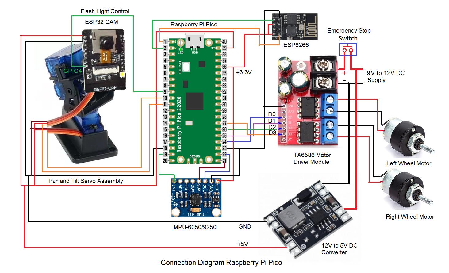
Two DC motors are fitted to a suitable base frame along with the wheels. Pan & tilt assembly (fitted with two micro servos) is mounted at suitable location of the frame. A 12V battery is mounted on the base frame. Required electronic modules are suitably placed on the base frame and are connected as per the connection diagram shown in ‘Schematic’ section.Typical arrangement is shown in below figure
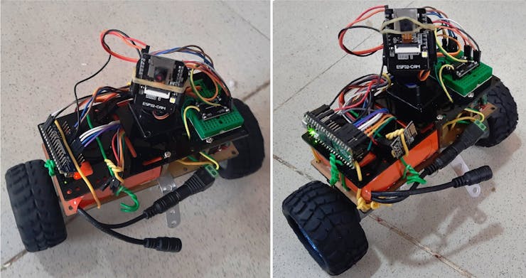
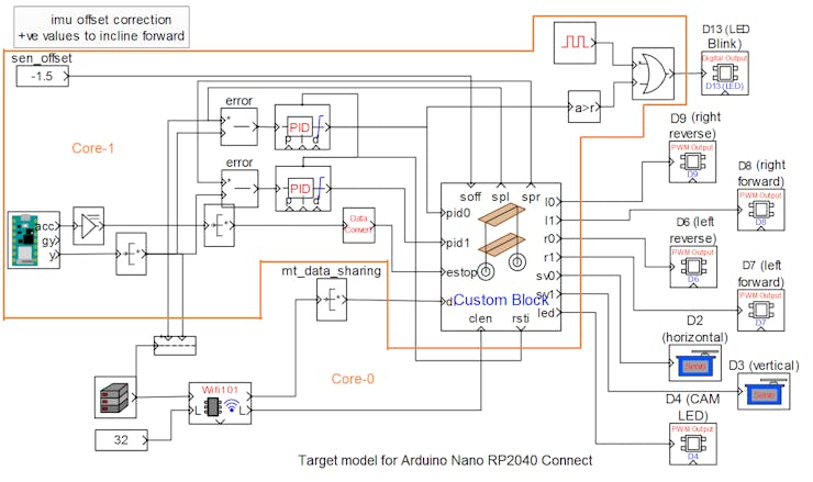
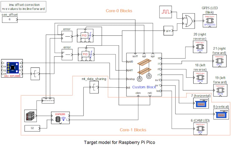
Typical arrangement - Arduino Nano RP2040 Connect (left) and Raspberry Pi Pico (right)
This project is build and tested separately on two micro-controllers, Arduino RP2040 Connect and Raspberry Pi Pico. These micro-controller boards are used as the main controller for the robot. They are used in dual core mode and are over clocked to 200MHz and 250MHz for Arduino RP2040 and Raspberry Pi Pico respectively to meet the response times required for balancing the robot and simultaneously communicating with the host PC through WiFi.
Arduino RP2040 is having on-board IMU and WiFi, as such external components required are minimum. Core-0 is used for WiFi communication and all PWM blocks for driving wheels and camera pan & tilt servos. Core-1 is extensively used for IMU and blocks required for balancing the robot.
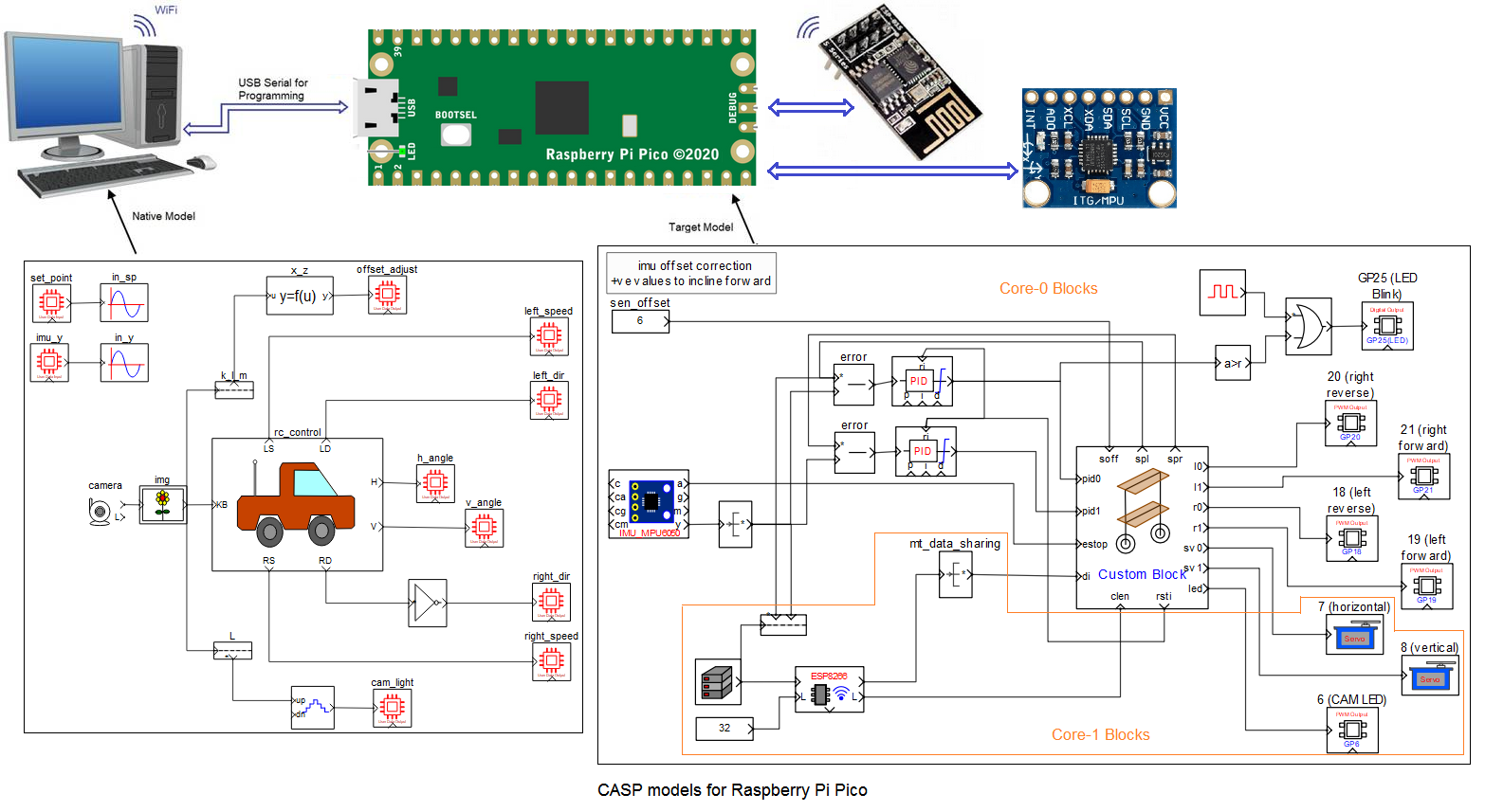
For Raspberry Pi Pico, Core-0 is used for the blocks required for balancing the robot and core-1 is used for blocks involved in remote communication and manual control of the robot and camera assembly. Inertial measurement unit (IMU) MPU-6050 (or MPU-9250) is used for sensing the inclination (here roll angle because of the mounting direction of IMU) angle of the robot. It communicates with the on-board micro-controller using I2C interface. ESP8266 WiFi module is used for communicating with remote host PC through WiFi. It communicates with the on-board micro-controller using serial interface.
ESP32 Camera module is mounted on the pan & tilt assembly for capturing live video and stream to the host PC. Flashlight present on the ESP32-CAM module is controlled manually from the host PC during low light conditions.
A 9V to 12V battery is used to power the entire circuitry on the robot. A 9V/12V to 5V DC step down converter is used to provide required 5V supply to power the micro-controller, servos and ESP32camera module.
Software Development
A) Configuring ESP32 Camera
ESP32 Camera shall be properly programmed with valid IP address before using it in the project. Please refer to our ESP32-CAM example for details on how to program the module. User may also refer to abundant material available on the internet regarding this subject.
B) Software for micro-controller and native targets
CASP software is used to quickly create models and generate binary code for the on-board micro-controller target and native PC. This software enable users to graphically visualize the signal at any point of the model in real time. This feature is extensively used while tuning the PID controller.
A part from normal CASP blocks two custom blocks (one in the target model and the other in the native model) are used in the models to develop logics that are not possible through normal CASP blocks and to reduce total block count. Source code for the custom blocks is available to the user.
Custom block used in the native model on the host PC generates required control signals when user presses certain keys for controlling the movements of the robot.
Custom block used in the target model modify the inclination angle set point (that is fed to the error block) for navigating the robot based on the user commands from the host PC and also conditions the PID controllers output signals before driving the motors. User can take a look at the configuration and source code of these custom blocks and learn how to integrate the blocks in CASP models along with other blocks. User can go through our video tutorial on how to create a custom block at this link.
Two models are developed to achieve desired objective.
B.1) Target Model that runs on Arduino RP2040 Connect and Raspberry Pi Pico consists of
1) Blink logic that indicates the system is running as well as whether the IMU is working properly or not.
2) IMU, PID controller custom block and other supporting blocks that maintain the balance of the robot.
3) WiFi and supporting blocks that receives required control signals from host PC.
4) PWM and servo blocks that are mapped to the pins of the micro-controller.
Following are the steps to properly program the target board.
1) Connect the target to the host PC via a USB cable.
2) Note the serial port number to which the board that is connected to the host PC, from the host operating system.
3) Run CASP and load the ‘rc_target_arduino’ project for Arduino RP2040 target or ‘rc_target_rpi’ project for Raspberry Pi target. Open the workspace file and adjust various block parameters as described in the Adjustments section.
4) The WiFi communication block is set to Station mode. User may need to enter SSID and password of the network to which the device should be connected. The Local IP address parameter shall be configured as assigned by the network DHCP client of the network.
5) Open Home->Simulation->Setup Simulation Parameters menu item. Under TargetHW->General tabs set ‘Target Hardware Programmer Port’ parameter to the serial port to which the board is connected.
6) Build the model and program the board by clicking on Run button.
B.2) Native Model that runs on Host PC consists of
1) Camera block that receives live video from the ESP32 Camera. IP address of the ESP32 Camera shall be entered in block parameters of this block.
2) Image display block to display the live video received from the camera. It is also configured to output keyboard and mouse signals.
3) RC control block: It is a custom block that receives keyboard and mouse signals from the image display block and generates suitable control signals for controlling the robot motion and its head (pan & tilt) movements.
4) GPIO blocks that maps to the target model via the WiFi communication channel.
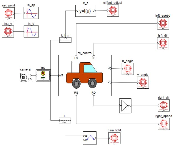
Native model that runs on host PC
Following are the steps to run the native model on the host PC
1) Before continuing, the host PC shall be connected to the same network as the device is connected. The robot should be up and running.
2) Load the ‘rc_native’ project.
3) Click on Home->Simulation->Configure Simulation IO menu item.
4) ‘Configure Simulation Hardware’ window will open. Under Native Nodes and GPIO Device Nodes, change the IP addresses marked in the below figure (by double clicking on the item) to respective local and device IP addresses.
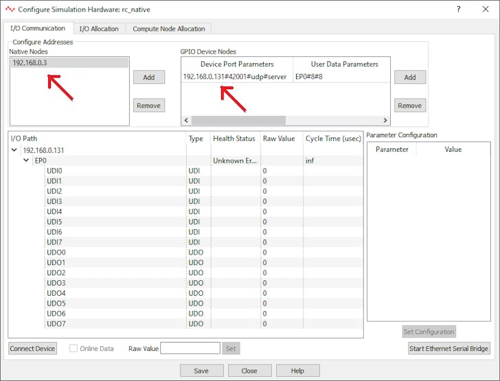
Configure Simulation Hardware window to change IP addresses of native node (host PC) and GPIO device (Raspberry Pi Pico)
5) Click on ‘Connect Device’ button and check the ‘Online Data’ check box. The program should now communicate with the target with cycle time around 30msecs. Target board is now available as end point ‘EP0’ to the native model. Native model can use this end point to connect to respective IOs on the target.
6) Click on ‘Save’ button to save the configuration and close the window.
7) Run the model by clicking on the Run button. A simulation panel window should open and communicate with the board.
8) Screen shot of the output simulation panel running on host PC is shown below.
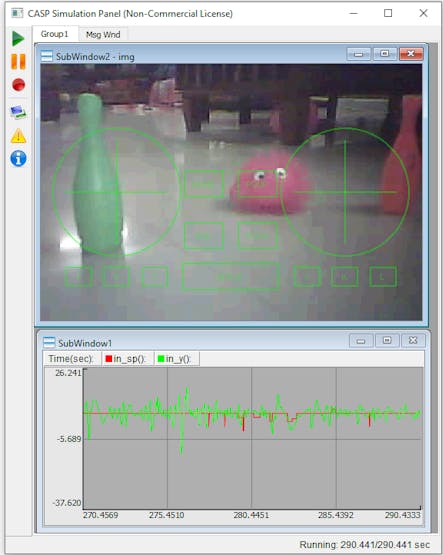
Simulation Panel Window with on-board camera live video
Adjustments
On-board Micro-controller Target
1) IMU sensor offset value (sen_offset block) is required to be adjusted if the center of gravity of the robot is shifted towards one side and/or floor is having some slope.
2) Proportional, integral and derivative parameters of the PID controllers shall be tuned based on the robot wheel diameter, wheel backlash, driving motor gear ratio, IMU sensor location, robot weight, height and center of gravity.
3) ‘PWM Minimum Offset’ parameter of the custom block shall be adjusted to match with the minimum value required to just rotate the motors on load.
4) Any other required logics to improve the performance of the robot may be done in the source code of the custom block.
5) Wheel motor connections may be reversed to get forward or backward movement when W and S are pressed.
Native Target
1) Logics for generating forward and reverse motor rotation are developed to match with the motor driver IC i.e. TA6586 used in the project. User may modify the logics suitably if other driver IC is used.
2) Servo motors may require some alignments to face towards robot forward direction for the default angle specified in the rc_control block parameters.
3) Base speed, speed limits and other parameters related to the navigation are adjustable from the rc_control block parameters.
Control Methodology
1) The simulation panel window shown above accepts keyboard & mouse inputs when it is active.
2) User can use keys W – to move forward, S – to move backward, A – to rotate left on center and D – to rotate right on center.
3) Combination of keys W/S & A/D can be used to take left and right turns while moving forward or backward.
4) Speed can be increased temporarily by using the shift key along with the above keys. Base speed can be adjusted by using Page Up & Page Down keys.
5) Keys K and M can be used to adjust the offset inclination angle where the robot stabilizes at a given location. This value is required if the center of gravity of the robot is shifted towards one side and/or floor is having some slope.
6) Vertical and horizontal servo angles (from -90 to +90 deg) for head position control can be controlled by mouse movements.
7) Key ‘G’ is used to position both servos at default angle.
8) Key 'L' is used to ON/OFF the flash LED light of the ESP32 camera.
Schematics
Connection Diagram for Arduino Nano RP2040 Connect
Connection Diagram for Raspberry Pi Pico
Models for Arduino Nano RP2040 Connect
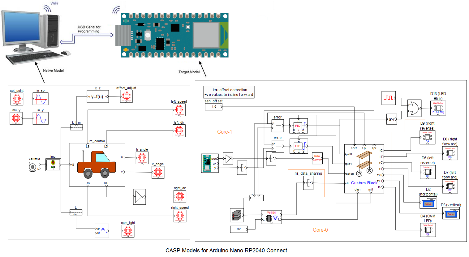
Models for Raspberry Pi Pico
The article was first published in hackster, September 17, 2022
cr: https://www.hackster.io/aadhuniklabs/self-balancing-wifi-controlled-robot-with-pantilt-camera-4b5762
author: aadhuniklabs


