
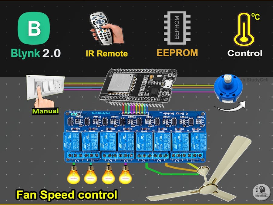
Make IoT-based Home Automation using ESP32 Blynk with the Fan Speed control, sensor, and IR remote control relay with real-time feedback.
Things used in this project
Hardware components
Hand tools and fabrication machines
Soldering iron (generic)
Story
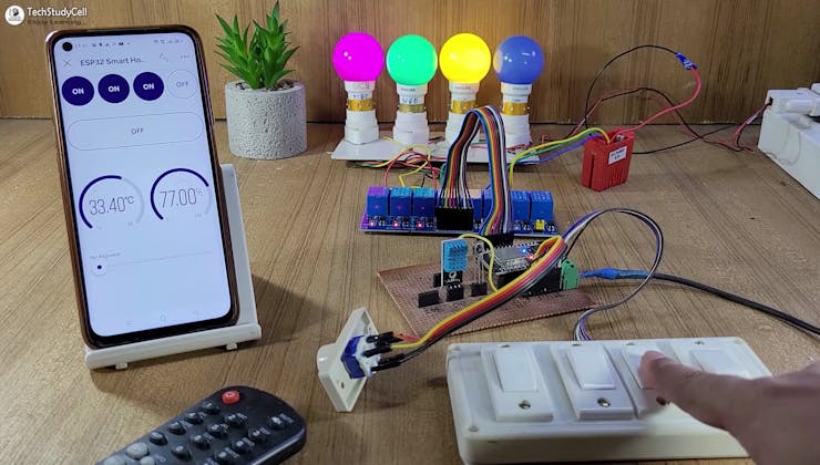
In this IoT project, I have shown how to make IoT-based Smart Home Automation using ESP32 Blynk with the Fan Speed control, sensor, and IR remote control relay with real-time feedback.

So, you can easily make this home automation project at home just by using an ESP32 and relay module. Or you can also use a custom-designed PCB for this project.
Tutorial Video on IoT Project using ESP32 & Blynk
In the tutorial video, I have shown all the steps to make this Blynk home automation system.
This Blynk ESP32 control smart relay has the following features:
Control home appliances with WiFi (Blynk IoT App). Control ceiling fan speed with Blynk, IR Remote, & selector switch. Control home appliances with an IR remote. Control home appliances with manual switches or push buttons. Save thelast GPIO state in ESP32 flash memory. Monitor real-time room temperature in the Blynk IoT App Monitor real-time feedback in the Blynk IoT App. Control appliances, and fan speed without WiFi.
Required components for the ESP32 Project
So, you can easily make this home automation project at home just by using an ESP32 and relay module. Or you can also use a custom-designed PCB for this project.
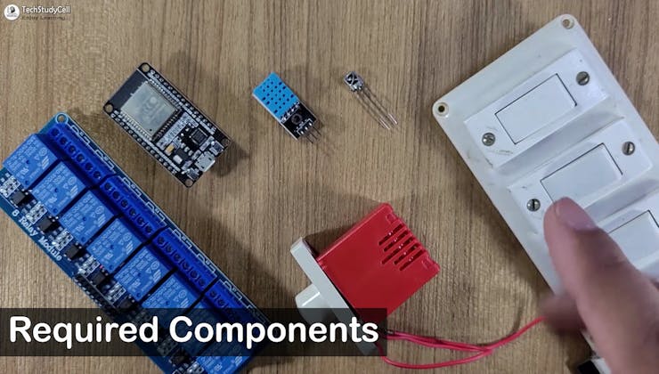
Required components:
ESP32 DevKIT V14-channel 5V SPDT Relay ModuleDHT11 SensorTSOP1838 IR Receiver (with metallic case)Switches or PushbuttonsAny IR Remote4-step Fan RegulatorOR (2.2uf & 3.3uf 250V Capacitor, 2.2-ohm 1/2W Resistors, 220k 1/4W Resistors, and 4-step selector switch)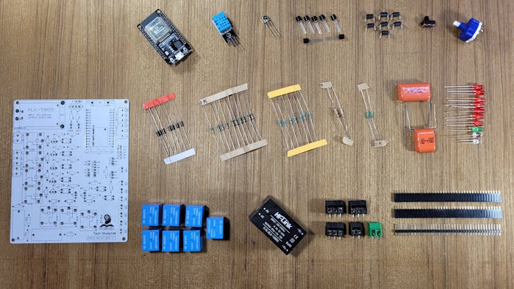
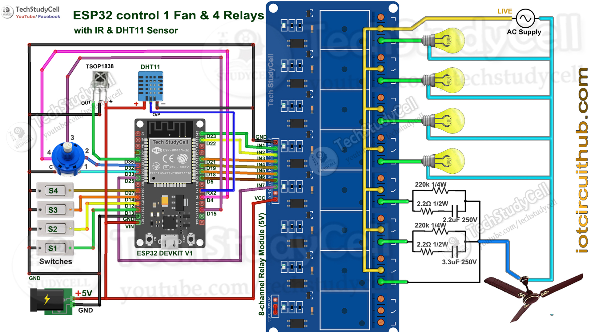
Circuit Diagram of the ESP32 IoT Project

The circuit is very simple, I have used the GPIO pins D23, D22, D21 & D19 to control the 4 relays.
And the GPIO pins D13, D12, D14 & D27 are connected with switches, and GPIO D33, D32, D15 & D4 are connected with a 4-step selector switch to control the 4 relays manually.
I used the INPUT_PULLUP function in Arduino IDE instead of the pull-up resistors.
IR remote receiver (TSOP1838) connected with D35. And the DHT11 sensor is connected to RX2 (GPIO-16).
I have used a 5V mobile charger to supply the smart relay module.
Please take proper safety precautions while working with high voltage.
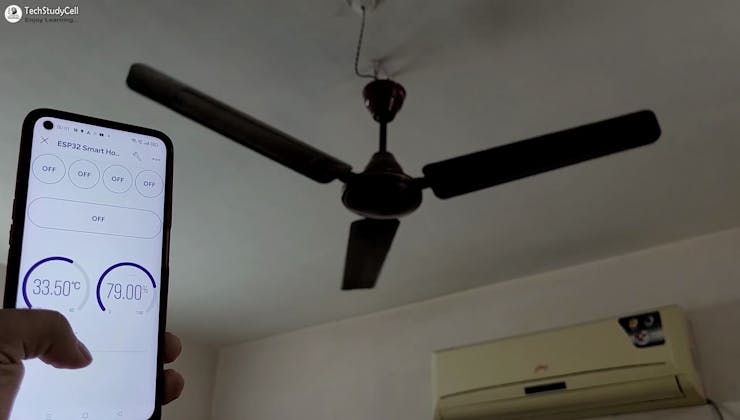
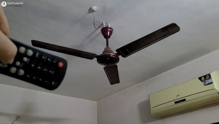
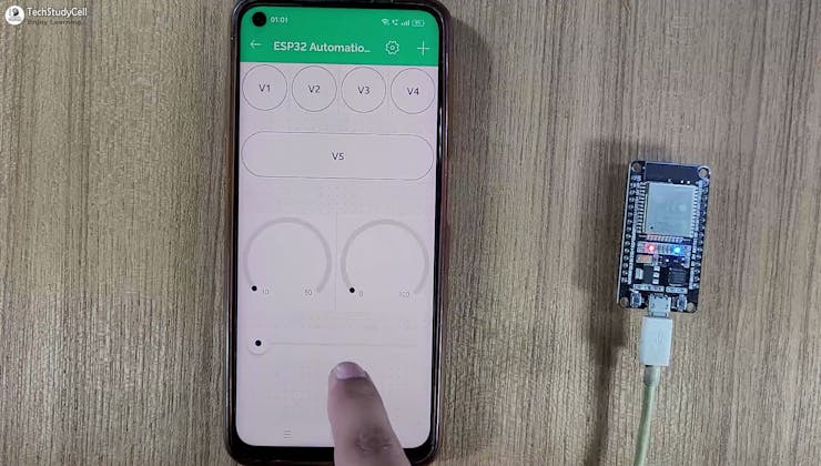
Control Fan Speed With Blynk IoT App

Control the speed of the ceiling fan from anywhere in the world from the Blynk IoT App. If the WiFi is connected, you can also monitor the real-time feedback in the Blynk.
Control Fan Speed With IR Remote and Selector Switch
You can use any IR remote to control the fan speed. I have used 2 buttons to increase and decrease the fan speed from the IR remote.
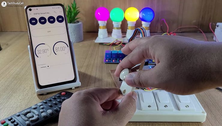
You can also use a selector switch to control the fan speed manually if the WiFi is not connected.
Control Relays With Blynk, IR Remote, and Manual Switch
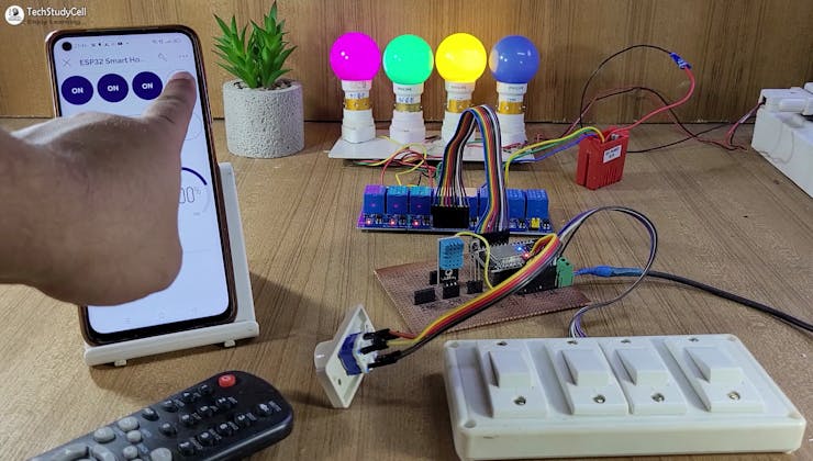
If the ESP32 is connected to WiFi, you can control the home appliances from Blynk IoT App.
You also use multiple smartphones to control the appliances with Blynk App. For that, you have to log in same Blynk account from all the smartphones.
This way, all smartphones will be in the sink to the Blynk server. You can control, and monitor the real-time status of the relays, room temperature & humidity from anywhere in the world in the Blynk IoT App.
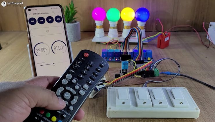
You can always control the relays from the IR remote or switches. For this project, you can use any IR remote.
You can monitor the real-time feedback in the Blynk IoT App if the WiFi is connected.
I have explained how to get the IR codes (HEX codes) from any remote in the following steps.
Please refer to the circuit diagram to connect the switches.
Design the PCB for This Smart Home System
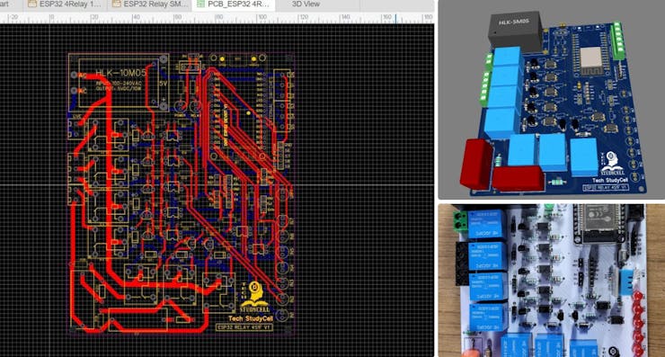
To make the circuit compact and give it a professional look, I designed the PCB after testing all the features of the smart relay module.
You can download the PCB Gerber, BOM, and "pick and place" files of this ESP32 control relay PCB from the following link:
GitHub link to Download PCB Gerber File
For this project, I have the JLC SMT Service while ordering the PCB.
Create Blynk Cloud FREE Account & Blynk Template
For this smart house project, I have used the Blynk IoT Cloud Free plan.
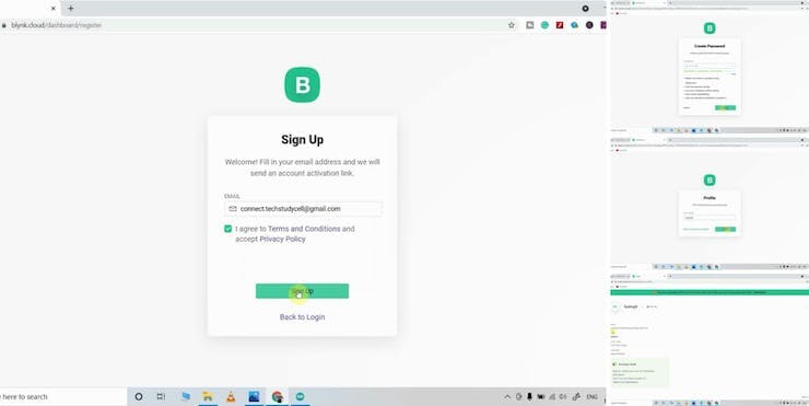
Click on the following link to create a Blynk Cloud account.
https://blynk.cloud/dashboard/register
Enter your email ID, then click on "Sign Up". You will receive a verification email. Click on Create Password in the email, Then set the password, and click on Next. Enter your first name, and click on Done.
After that Blynk cloud dashboard will open.
Create a New Template in Blynk Cloud
First, you have to create a template in the Blynk cloud.
Click on New Template. Enter a template name, select the hardware as ESP32, and the connection type will be WiFi.Then click on DONE.
You will get the BLYNK_TEMPLATE_ID and BLYNK_DEVICE_NAME after creating the temple.
Create a Datastream in Blynk Cloud
After that, you have to create Datastreams. Here I will control 4 relays, so I have to create 4 Datastreams. And for Fan Speed Control 1 Datastream.
Steps to add Datastreams.
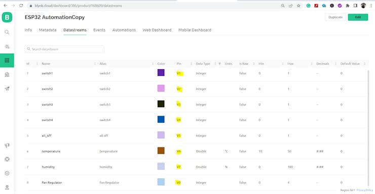
Go to the Datastreams tab. Click on New Datastream and select Virtual Pin. Enter a name, select the virtual pin V1, and the datatype will be Integer. Then click on Create.
In a similar way, create 4 datastreams with virtual pin V1 to V4. And 1 datastream (V5) to turn off all the relays. And for Fan Speed Control 1 Datastream (V0) with MAX value 4 & MIN value = 0.
And for the Temperature and humidity, I have used V6, & V7 (Please refer to the picture or tutorial video).
Set Up Blynk Cloud Web Dashboard
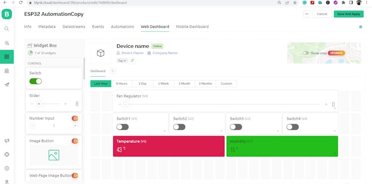
Now go to the Web Dashboard tab.
Drag and drop 4 Switch widgets, 1 Slider widget, and 2 Level widgets.
Go to the settings of each widget, and select a Datastream.
Please refer to the tutorial video for more details.
Then click on Save to save the template.
Add Device Using Template in Blynk IoT
Steps to add a device in the Blynk IoT cloud:
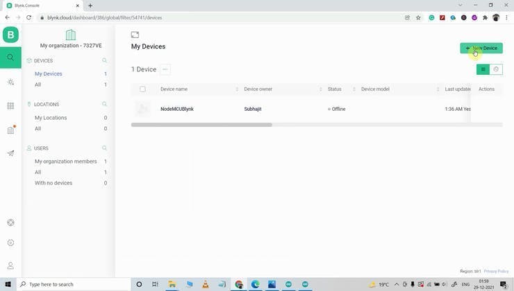
First, go to Device, then click on "New Device".
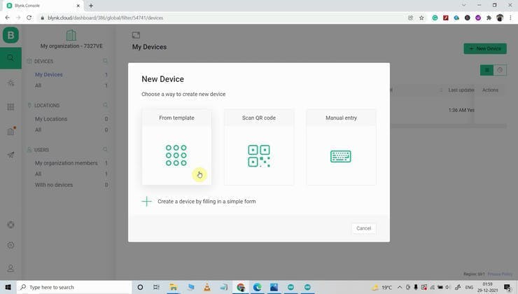
Click on "From template".
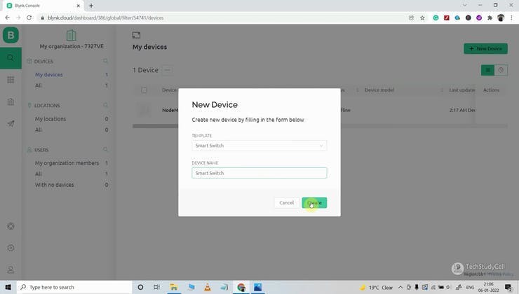
Select the Template, and give the device name. Click on Create.
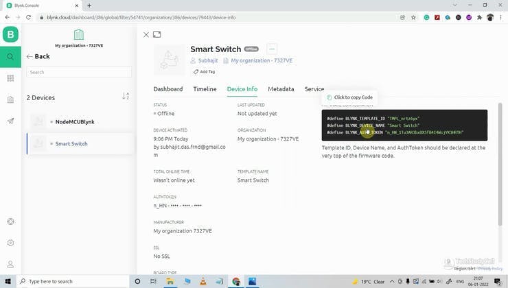
Then in the device info tab, you will get the Blynk Auth Token, Template ID, and Device Name. All these details will be required in the code.
Get the IR Codes (HEX Code) From the Remote
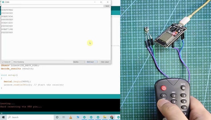
Now, to get the HEX codes from the remote, first, we have to connect the IR receiver output pin with GPIO D35.
And give the 5V across the VCC and GND. The IR receiver must have a metallic casing, otherwise, you may face issues.
Then follow the following steps to get the HEX codes
Install the IRremote library in Arduino IDE Download the attached code, and upload it to ESP32. Open Serial Monitor with Baud rate 9600. Now, press the IR remote button. The respective HEX code will populate in the serial monitor.
Save all the HEX codes in a text file.
Program the ESP32 for This Blynk Project
GitHub Link to download the Source Code
Download and install the following libraries in Arduino IDE
Blynk Library (1.1.0): https://github.com/blynkkk/blynk-library AceButton Library (1.9.2): https://github.com/bxparks/AceButton IRremote Library (3.6.1): https://github.com/Arduino-IRremote/Arduino-IRremote DHT Library (1.4.3): https://github.com/adafruit/DHT-sensor-library
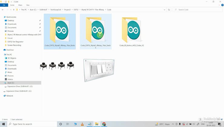
Now open the main sketch (code).
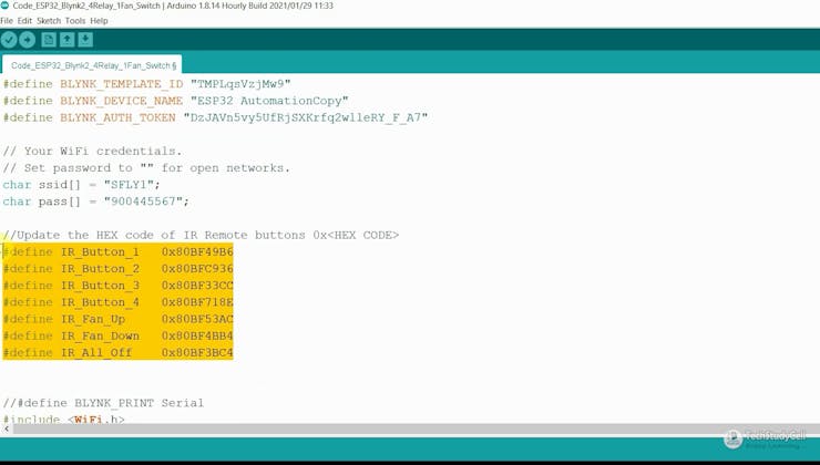
In the code, you have to update the BLYNK_TEMPLATE_ID, BLYNK_DEVICE_NAME, Auth Token, WiFi Credentials.Then update the HEX codes of the IR remote as shown in the tutorial video. After that, select the DOIT ESP32 DEVKIT V1 board and proper PORT. Then upload the code to ESP32 Board.
While uploading the code to ESP32, if you use the PCB then you will see the "Connecting....___" text, then press and hold the BOOT button and then press the EN button, after that release both buttons.
Install Blynk IoT App to Configure Mobile Dashboard
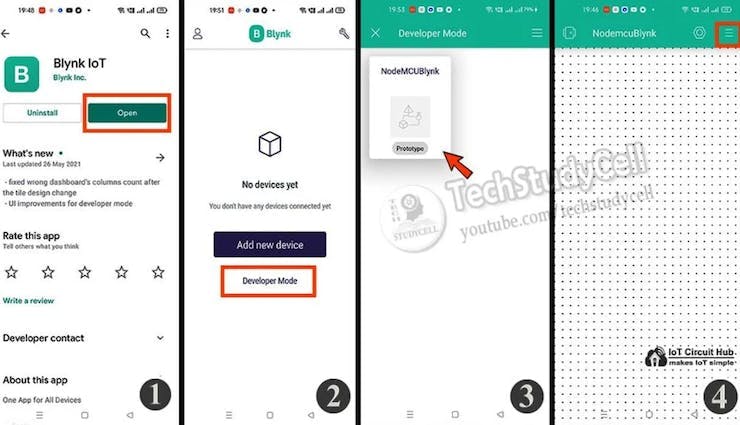
Install the Blynk IoT app from Google Play Store or App Store. Then log in. Go to Developer Mode. Tap on the template that you have already made. Now go to the Widget box (on the right) to add widgets. Add 5 Button widgets, 1 Slider, and 2 Gauge widgets from Widget Box. Go to the Button widget settings. Enter the name, select Datastream, Mode will be Switch. Then exit.
After setting all the Buttons tap on exit.
Finally!! the Blynk Smart Home System Is Ready

Now you can control your home appliances in a smart way.
I hope you have liked this new Blynk IoT home automation project. I have shared all the required information for this project.
I will really appreciate it if you share your valuable feedback. Also if you have any queries please write in the comment section.
Thank you & Happy Learning.
Schematics
Circuit of the ESP32 IoT Project with Blynk IoT
Circuit of the ESP32 IoT Project with Blynk IoT
Code
Source Code for the ESP32 IoT Project
https://github.com/techstudycell/ESP32-Blynk-With-Fan-Speed-Control-Sensor/tree/main/Code


