
Just a simple Arduino-based RFID system to control stepper motor in a prototype circuit.
Things used in this project
Hardware components
Story
RFID-based control system design is based on microcontroller control system which by using Arduino UNO that works with ATmega328P microchip which is fully suitable for such applications, the RFID module used is MFRC522RFID module which is a reliable and compatible component to work with Arduino's boards, for door control a 28BJY-48 stepper motor is used that can be controlled in both directions and also number of steps and speed can be controlled, the stepper motor is derived using ULN2003 high voltage, high current Darlington array Integrated circuit. A 16x2 LCD display is used as output component to show different situations of the system, also an electric buzzer or a piezo transducer is used to generate system sounds and alarming indifferent situations, a LED is used as indicators also with different situations, and finally a push bottom is used for admin to erase the EEPROM of the microcontroller, the implementation also uses some wires, jumpers, and breadboards for testing the functionality of the system. the system block diagram below shows the system components that used in design and implementation of the proposed RFID access control system.
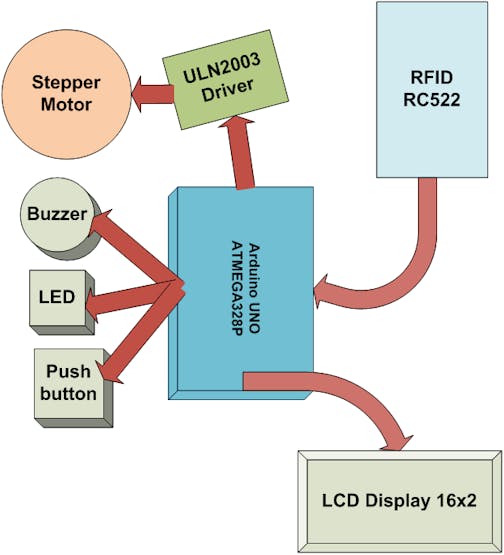
RFID System block diagram
See it here :
System components
The actual system components used in the implementation as follow:
Ø Arduino UNO board with ATmega328P microcontroller.
Ø MFRC522 RFID Module with tags.
Ø 28BJY-48 stepper motor.
Ø ULN2003 stepper driver Module.
Ø 16x2 LCD display.
Ø 1xBuzzer.
Ø 1xLED.
Ø 1xPush button.
Ø 10kΩ variable resistor & 330Ω resistor.
Arduino UNO board
The Arduino Uno is one of the most common and widely used Arduino processor boards. There are a wide variety of shields (plug in boards adding functionality).
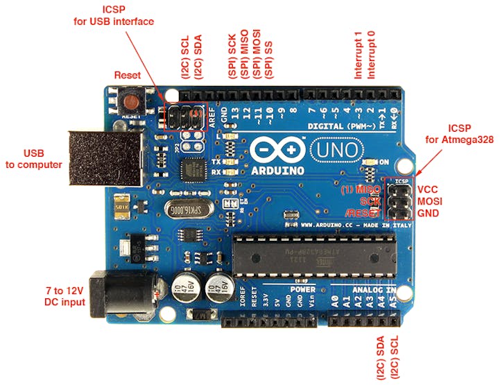
Arduino UNO board
The board can be powered from the USB connector (usually up to 500 ma for all electronics including shield), or from the 2.1 mm barrel jack using a separate power supply when you cannot connect the board to the PC’s USB port.the Arduino UNO has the following specifications:
Ø Microcontroller: ATmega328
Ø Operating Voltage: 5V
Ø Uno Board Recommended Input Voltage: 7 – 12 V
Ø Uno Board Input Voltage Limits: 6 – 20 V
Ø Digital I/O Pins: 14 total –6 of which can be PWM
Ø Analog Input Pins: 6
Ø Maximum DC Current per I/O pin at 5VDC: 40ma
Ø Maximum DC Current per I/I pinat 3.3 VDC: 50ma
Ø Flash Memory: 32KB (0.5KBused by bootloader)
Ø SRAM Memory: 2KB
Ø EEPROM: 1KB
Ø Clock Speed: 16 MHz
The main processor on Arduino UNO is an ATmega328 microcontroller which includes the following features:
Ø Two 8-bit Timer/Counters with Separate Prescaler and Compare Mode
Ø One 16-bit Timer/Counter with Separate Prescaler, Compare Mode, andCapture Mode
Ø Real Time Counter with Separate Oscillator
Ø Six PWM channels
Ø Six channel 10 bit ADC including temperature measurement
Ø Programmable Serial USART
Ø Master/Slave SPI Serial Interface
Ø Byte-oriented 2 wire Serial Interface (Philips I2C compatible)
Ø Programmable Watchdog Timer with Separate On-chip Oscillator
Ø On-chip Analog Comparator
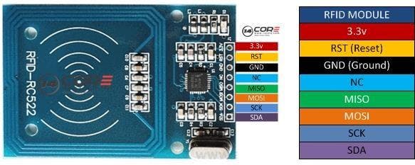
MFRC522 RFIDModule
RFID means radio-frequency identification. RFID useselectromagnetic fields to transfer data over short distances. RFID is useful toidentify people, to make transactions, etc…
RFID system can be used to open a door. For example, only theperson with the right information on his card is allowed to enter. An RFIDsystem uses:
Ø tags attached to the object to be identified, in figure keychainand an electromagnetic card. Each tag has his own identification (UID).
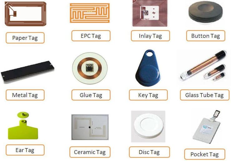
RFID tags
Ø two-way radio transmitter-receiver, the reader, that send a signal to the tag and read its response as shown:
RFID Transceiver
MF RC522 is used in highly integrated 13.56MHz contactlesscommunication card chip to read and write, of NXP for “three†and theapplication launched a low voltage, low cost, small size, non-contact card chipto read and write, intelligent instruments and portable handheld devicesdeveloped better.
The MF RC522 use of advanced modulation and demodulation conceptcompletely integrated in the 13.56MHz all kinds of passive contactlesscommunication methods and protocols. 14443A compatible transponder signal. Thedigital part handles the ISO14443A frames and error detection. Inaddition, support Quick CRYPTO1 encryption algorithm, the term verificationMIFARE series. MFRC522 support MIFARE series of high-speed non-contactcommunication, two-way data transfer rates up to 424kbit / s. As 13.56MHzhighly integrated card reader series chip new family, the MF RC522 MF RC500 MFRC530 there are many similarities, but also have many of the characteristicsand differences. Communication between it and the host SPI mode, helps toreduce the connection, reduce PCB board volume and reduce costs.
MF522-AN module uses Philips MFRC522 original chip design circuitcard reader, easy to use, low cost, and suitable for equipment development, thedevelopment of advanced applications reader users, the need for RF cardterminal design / production users. This module can be directly loaded into thevariety of reader molds. Module uses voltage of 3.3V, simple few lines throughthe SPI interface directly with any user CPU board is connected to thecommunication module can guarantee stable and reliable work, reader distance.MF RC522 introduces the following specifications:
Ø Working Current: 13—26mA/ DC 3.3V
Ø Standby Current: 10-13mA/DC 3.3V
Ø Sleeping Current: <80uA
Ø Peak Current: <30mA
Ø Working Frequency: 13.56MHz
Ø Card Reading Distance: 0~60mm(mifare1 card)
Ø Protocol: SPI
Ø Data Communication Speed: Maximum 10Mbit/s
Ø Card Types Supported: mifare1 S50, mifare1 S70, mifare UltraLight, mifare Pro, mifare Desfire
Ø Working Temperature: -20—80 degree
Ø Storage Temperature: -40—85 degree
Ø Humidity: relevant humidity 5%—95%
Ø Max SPI Speed: 10Mbit/s
Ø Dimensions: 40mm×60mm
Figure(3-5): RC522 RFID ModuleSchematic
StepperMotor
A stepper motor is an Electromechanical device which converts electrical pulses into discrete mechanical movements. The shaft or spindle of a stepper motor rotates in discrete step increments when electrical command pulses are applied to it in the proper sequence. The motors rotation has several direct relationships to these applied input pulses. The sequence of the applied pulses is directly related to the direction of motor shafts rotation.The speed of the motor shafts rotation is directly related to the frequency of the input pulses and the length of rotation is directly related to the number of input pulses applied. One of the most significant advantages of a stepper motor is its ability to be accurately controlled in an open loop system. Open loop control means no feedback information about position is needed. This type of control eliminates the need for expensive sensing and feedback devices such as optical encoders. the position is known simply by keeping track of the input step pulses.
Stepper motor
Features ofstepper motors:
1) The rotation angle of the motor is proportional to the input pulse.
2) The motor has full torque at standstill(if the windings are energized).
3) Precise positioning and repeatability of movement since good stepper motors have an accuracy of – 5% of a step and this error is non cumulative from one step to the next.
4) Excellent response to starting/stopping/reversing.4.
5) Very reliable since there are no contact brushes in the motor. Therefore the life ofthe motor is simply dependant on the life of the bearing.
6) The motors response to digital input pulses provides open-loop control, making the motor simpler and less costly to control.
7) It is possible to achieve very low speed synchronous rotation with a load that is directly coupled to the shaft.
8) A wide range of rotational speeds can be realized as the speed is proportional to the frequency of the input pulses.
28BYJ-48Stepper motor specifications
Ø Rated voltage : 5VDC
Ø Number of Phase : 4
Ø Speed Variation Ratio : 1/64
Ø Stride Angle : 5.625° /64
Ø Frequency : 100Hz
Ø DC resistance : 50O±7%(25℃)
Ø Idle In-traction Frequency : > 600Hz
Ø Idle Out-traction Frequency : > 1000Hz
Ø In-traction Torque >34.3mN.m(120Hz)
Ø Self-positioning Torque >34.3mN.m
Ø Friction torque : 600-1200 gf.cm
Ø Pull in torque : 300 gf.cm
Ø Insulated resistance >10MO(500V)
Ø Insulated electricity power :600VAC/1mA/1s
Ø Insulation grade :A
Ø Rise in Temperature <40K(120Hz)
Ø Noise <35dB(120Hz, No load, 10cm)
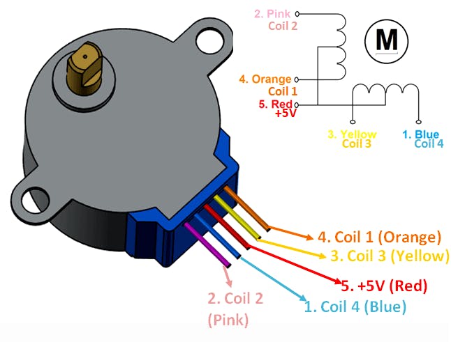
The bipolar stepper motor usually has four wires coming out of it.Unlike unipolar steppers, bipolar steppers have no common center connection.They have two independent sets of coils instead. We can distinguish them from unipolar steppers by measuring the resistance between the wires. You should findtwo pairs of wires with equal resistance. If you’ve got the leads of your meter connected to two wires that are not connected (i.e. not attached to the samecoil), you should see infinite resistance (or no continuity).
Figure(3-7): 28BYJ-48 Stepper motor pins wiring
The simplest way of interfacing a unipolar stepper to Arduino is touse a breakout for ULN2003A transistor array chip.
Table(3-1): Operating sequence of stepper motor
ULN2003Stepper motor driver
The ULN2003A contains seven Darlington transistor drivers and is somewhat like having seven TIP120 transistors all in one package. The ULN2003A can pass up to 500 mA per channel and has an internal voltage drop of about 1V when on. It also contains internal clamp diodes to dissipate voltage spikes when driving inductive loads. To control the stepper, apply voltage to each of the coils in a specific sequence.
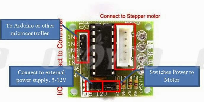
ULN2003 driver module
The driver board accepts a four bit command from any microcontroller and in turn applies the necessary power pulse to step the motor. At the heart of the driver is a ULN2003AN integrated circuit. The board can supply between 5V to 12V to the motor from an independent power supply. It also has a bank of LED’s that correspond to the input signals received from the controller. They provide a nice visual when stepping. Some typical stepper motor details:
Ø Model: 28KYJ-48
Ø Voltage: 5VDC
Ø Phase: 4
Ø Step Angle: 5.625° (1/64)
Ø Reduction ratio: 1/64
It takes 4096 steps to rotate the spindle 360°. It is impossible to see a single step. When testing it pays to have something distinct on the spindle to show it is turning. Physically connecting a microcontroller to the driver board is straight forward. Pick a free GPIO pin on an expansion header and run a wire from it to one of the input pins on the driver board. The driver board requires power. Power supply has to be sufficient power to drive the stepper motor. It is usually a good idea to use a separate power source to the one that is driving the microcontroller. Having wired a GPIO pins to the driver board we can test the interface. Set the GPIO pin high and the corresponding LED on the driver board will illuminate. Set it low and the LED turns off.
The motor steps when a specific combination of inputs are driven from the microcontroller. This is just a pulse of power, just enough to get the motor to step. This driver uses a very simple protocol. Applying a signal to an input pin causes power to be sent to the motor on a corresponding wire.
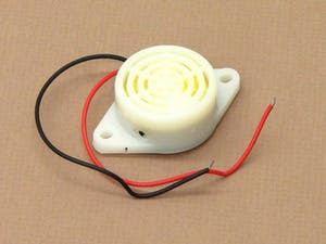
Buzzer
A buzzer or beeper is an audio signaling device, which may be mechanical, electromechanical, or piezoelectric. Typical uses of buzzers and beepers include alarm devices, timers and confirmation of user input such as a mouse click or keystroke.
Buzzer is an integrated structure of electronic transducers, DC power supply, widely used in computers, printers, copiers, alarms, electronic toys, automotive electronic equipment, telephones, timers and other electronic products for sound devices. Active buzzer 5V Rated power can be directly connected to a continuous sound, this section dedicated sensor expansion module and the board in combination, can complete a simple circuit design, to"plug and play."
Buzzer
The buzzer used here for generating sounds that indicates different situations of the system as in alarming, which has the following features:
Ø Buzzer diameter 1.15" x 0.58" thick
Ø Base 1.89" long with two mounting holes 0.13" in diameter
Ø Connecting wires 4" long
Ø Strong plastic housing
Ø Clear and loud
Ø Strong plastic construction with distinct and clear sound. These Buzzers are an essential electrical part for use in Physics electrical circuits and Sound experiments and other general lab use.
LED &Push button
The Light Emitting Diode is a device that converts electric current into optical energy which is used here as an indicator for different system situations, a Push button is a mechanical device that switches between two cases either LOW or HIGH which is used as input from admin to erase the EEPROM.
EEPROM
EEPROM (Electrically Erasable Programmable ROM) offer users excellent capabilities and performance. A single power supply is required. Write and erase operations are performed on a byte per byte basis.
The EEPROM cell is composed of two transistors. The storage transistor has a floating gate(similar to the EPROM storage transistor) that will trap electrons. In addition, there is an access transistor, which is required for the erase operation.
To have productselectrically compatible, the logic path of both types of product will give a“1†for erase state and a “0†for a programmed state.
SerialPeripheral Interface (SPI)
Serial Peripheral Interface (SPI) is an interface bus commonly used to send data between microcontrollers and small peripherals such as shift registers, sensors, and SD cards. It uses separate clock and data lines, along with a select line to choose the device you wish to talk to.
In SPI, only one side generates the clock signal (usually called CLK or SCK for Serial ClocK). The side that generates the clock is called the“masterâ€, and the other side is called the “slaveâ€. There is always only one master (which is almost always your microcontroller), but there can be multiple slaves (more on this in a bit).
When data is sent from the master to a slave, it’s sent on a dataline called MOSI, for “Master Out / Slave Inâ€. If the slave needs to send a response back to the master, the master will continue to generate a prearranged number of clock cycles, and the slave will put the data onto a third data line called MISO, for “Master In / Slave Outâ€.
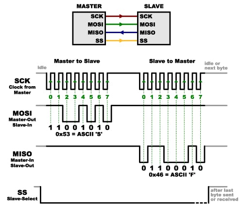
1 / 2 • SPI communication
Notice we said “prearranged†in the above description. Because the master always generates the clock signal, it must know in advance when a slave needs to return data and how much data will be returned. This is very different than asynchronous serial, where random amounts of data can be sent in either direction at any time. In practice this isn’t a problem, as SPI is generally used to talk to sensors that have a very specific command structure. For example, if you send the command for “read data†to a device, you know that the device will always send you, for example, two bytes in return. (In cases where you might want to return a variable amount of data, you could always return one or two bytes specifying the length of the data and then have the master retrieves the full amount).
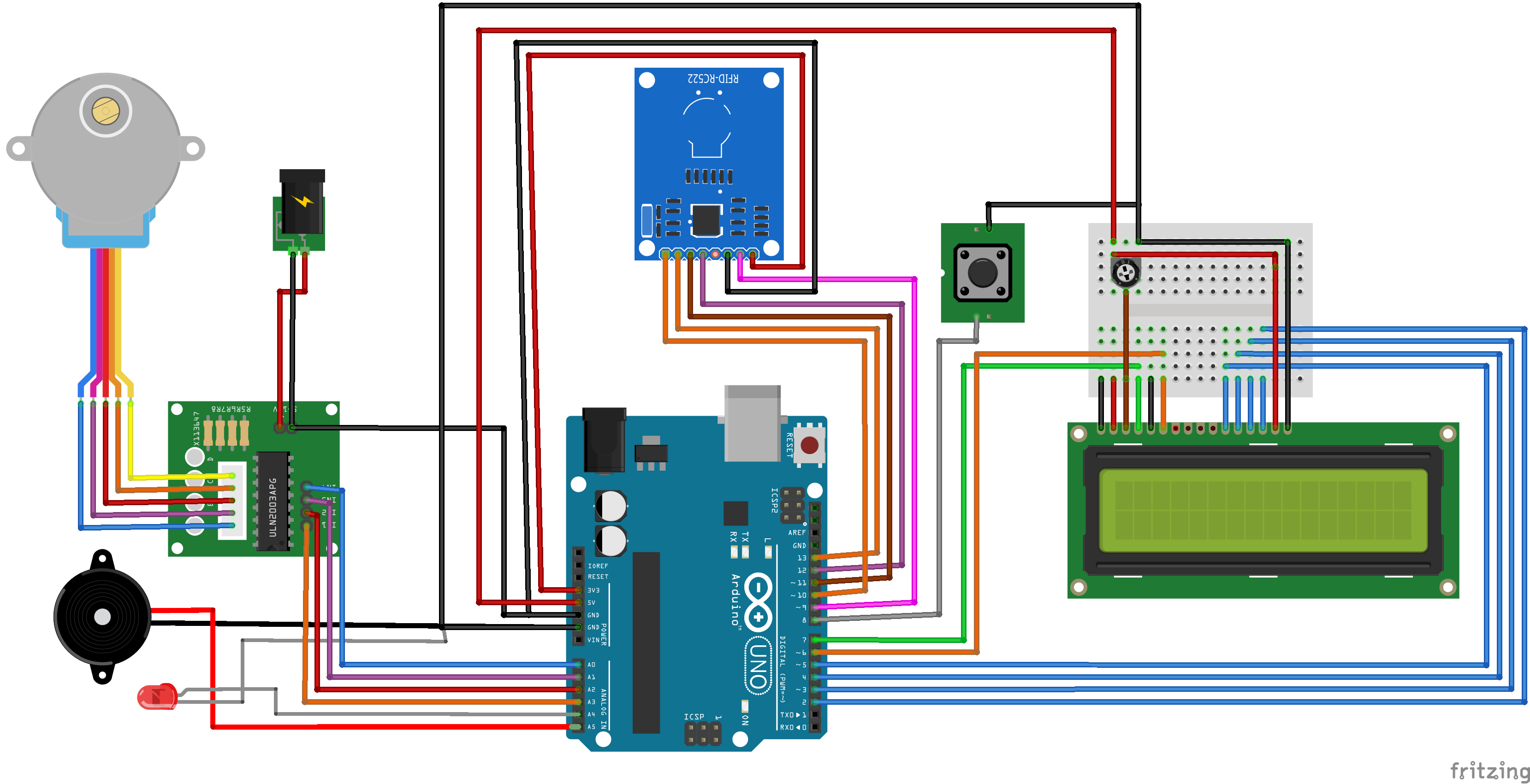
Circuit Schematic
The system connection in breadboard and wiring schematic used is shown in figure (3-16) below which show that RFID is connected to digital I/Orelated to SPI interface in Pins 9, 10, 11, 12, and 13. and the LCD uses six digitalI/O pins which are pins 2, 3, 4, 5, 6, and 7. the ULN2003 stepper driver is connected to analog I/O A0, A1, A2, and A3. the LED and buzzer is connected to A4and A5 pin, and the push button is connected to digital pin 8.
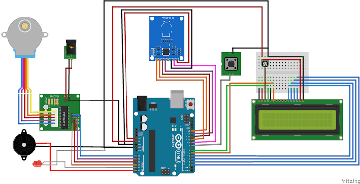
Circuit Schematic
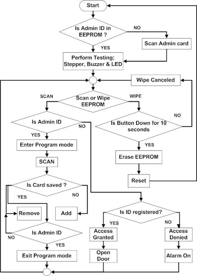
System Flow chart
The system first starts with check if there is previously saved Admin card in the EEPRM, if yes the system will continue and perform testing routine for LED, Buzzer, and stepper. and after test the system enters the normal mode which enables scanning RFID tags or Admin can push the wipe button to wipe the EEPROM, in normal mode scanning is performed normally if a tag ID scanned is saved previously then Access is granted and the stepper motor will turn on to open the door and turn back to close the door, if ID is not saved then alarm will go ON and access is denied. in normal mode if Admin card is detected then the system enters the programming mode which enables adding or removing IDs from the EEPROM by scanning the tag if the tag ID is already saved then it will be removed and if the tag is not registered before then it will be added, admin can exit the programming mode by scanning the Admin card again and the system will return to normal mode. if Admin press the push button it will indicates that it has to be hold on for 10 seconds to confirm the erasing routine and if button is released wiping operation will be cancelled otherwise the Wipe operation will be performed. this routine can be easly observed as in the flowchart in the following figure.
Results
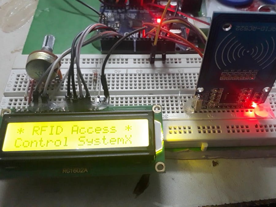
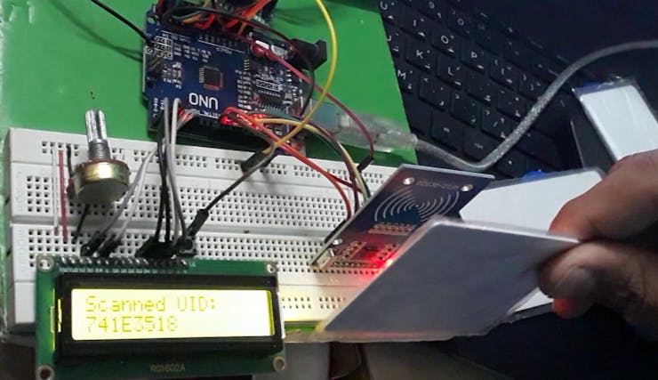
figure below shows the final implementation of the system in prototyped circuit using breadboard and all components used.
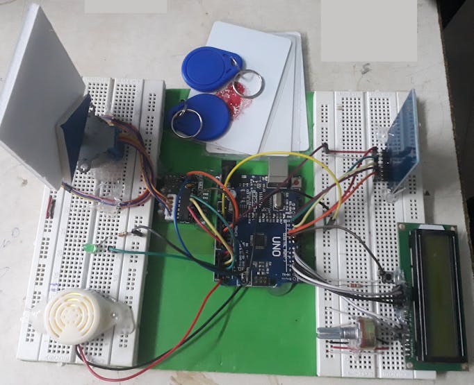
prototyped circuit
some pictures
1 / 2
Conclusion
In this project an RFID system based on Microcontrollers is proposed and implemented, the system is developed using Arduino UNO microcontroller board with RC522 RFID module the design was simple and efficient to meet the objective of the project, a stepper motor derived with ULN3003 is used to simulate door lock motor for opening and closing the door, an alarm sounds and indications is performed for different cases is applied by using a buzzer and LED. the system has two main users; Admin and normal user, admin can Wipe the EEPROM and add or remove a UID by entering the programming mode, a Normal user can check its tag and if the UID is registered before the access is granted and door open and close again, or if the scanned tag was not registered then the access will be denied and warning alarm will be generated by the buzzer. the system was successfully designed and implemented using Arduino IDE with C++ programming and all functions are tested correctly.
References
[1] Arduinoweb site: http://www.arduino.cc/
[2] ArduinoUno overview and image source: http://arduino.cc/en/Main/arduinoBoardUno#.UxNpBk2YZuG
[3] ATMega 328 datasheet: http://www.atmel.com/Images/doc8161.pdf
[4] MF RC522RFID module datasheet https://www.nxp.com/docs/en/data-sheet/MFRC522.pdf
[5] Steppermotor and ULN2003 http://eeshop.unl.edu/pdf/Stepper+Driver.pdf
[6] EEPROMTechnology http://smithsonianchips.si.edu/ice/cd/MEM96/SEC09.pdf
C++ Code for Arduino
#include <LiquidCrystal.h>
#include <X113647Stepper.h>
#include <EEPROM.h> // We are going to read and write PICC's UIDs from/to EEPROM
#include <SPI.h> // RC522 Module uses SPI protocol
#include <MFRC522.h> // Library for Mifare RC522 Devices
#define ON HIGH
#define OFF LOW
static const int STEPS_PER_REVOLUTION = 64 * 32; // steps per revolution for stepper motor
int i = 0; // Counter for alarm
int val = LOW, pre_val = LOW; // Alarming variables
const int Buzz = A5;
const int greenLed = A4;
const int wipeB = 8; // Button pin for WipeMode
bool programMode = false; // initialize programming mode to false
uint8_t successRead; //Variable integer to keep if we have Successful Read from Reader
byte stobuzzerCard[4]; // Stores an ID read from EEPROM
byte readCard[4]; //Stores scanned ID read from RFID Module
byte masterCard[4]; //Stores master card's ID read from EEPROM
// Create MFRC522 Pins.
constexpr uint8_t RST_PIN = 9;
constexpr uint8_t SS_PIN = 10;
MFRC522 mfrc522(SS_PIN, RST_PIN);
LiquidCrystal lcd(7, 6, 5, 4, 3, 2); // LCD Pins connectionRs,E,D4,D5,D6,D7
X113647Stepper myStepper(STEPS_PER_REVOLUTION, A0, A1, A2, A3);//stepper on pins A0 through A3
// Creat a set of new characters
byte smiley[8] = {0b00000, 0b00000, 0b01010, 0b00000, 0b00000,0b10001, 0b01110, 0b00000};
byte armsUp[8] = {0b00100, 0b01010, 0b00100, 0b10101, 0b01110,0b00100, 0b00100, 0b01010};
byte frownie[8] = {0b00000, 0b00000, 0b01010, 0b00000, 0b00000,0b00000, 0b01110, 0b10001};
void setup() {
pinMode(Buzz, OUTPUT);//Buzzer pin as Output
pinMode(greenLed,OUTPUT);// buzzer Led pin as Output
digitalWrite(Buzz, OFF);
digitalWrite(greenLed,OFF);
 pinMode(wipeB, INPUT_PULLUP); // Enable pin's pull up resistor
myStepper.setSpeed(6.5);// set the speed in rpm
lcd.begin(16, 2); // initialize the lcd
lcd.createChar (0,smiley); // load character to the LCD
lcd.createChar (1, armsUp); // load character to the LCD
lcd.createChar (2,frownie); // load character to the LCD
lcd.clear();
lcd.home (); // go home
lcd.print("* RFIDAccess *");
lcd.setCursor ( 0, 1); // go to the next line
lcd.print ("ControlSystemX");
delay(2000);
Serial.begin(9600); // Initialize serial communications with PC
SPI.begin(); // MFRC522 Hardware uses SPIprotocol
mfrc522.PCD_Init(); // Initialize MFRC522 Hardware
//If you set AntennaGain to Max it will increase reading distance
mfrc522.PCD_SetAntennaGain(mfrc522.RxGain_max);
Serial.println(F("RFID Access Control System")); // For debugging purposes
// ShowReaderDetails(); // Show details of PCD - MFRC522 Card Readerdetails
//Wipe Code - If theButton (wipeB) Pressed while setup run (powebuzzer on) it wipes EEPROM
if (digitalRead(wipeB)== LOW) { // when button pressed pinshould get low, button connected to ground
lcd.clear();
lcd.home (); // go home
lcd.print("Wiping10 sec");
lcd.setCursor ( 0, 1); // go to the next line
digitalWrite(Buzz,ON); // buzzer Led stays on to inform user we are going to wipe
Serial.println(F("Wipe Button Pressed"));
Serial.println(F("You have 10 seconds to Cancel"));
Serial.println(F("This will be remove all records and cannot beundone"));
bool buttonState =monitorWipeButton(10000); // Give user enough time to cancel operation
if (buttonState ==true && digitalRead(wipeB) == LOW) { // If button still be pressed, wipe EEPROM
 Serial.println(F("Starting WipingEEPROM"));
for (uint16_t x = 0;x < EEPROM.length(); x = x + 1) { //Loop end of EEPROM address
if (EEPROM.read(x)== 0) { //If EEPROM address0
// do nothing,already clear, go to the next address in order to save time and reduce writesto EEPROM
}
else {
EEPROM.write(x,0); // if not write 0 to clear, ittakes 3.3mS
}
}
Serial.println(F("EEPROM Successfully Wiped"));
lcd.print("EEPROMWiped");
lcd.print(char(1));
digitalWrite(Buzz,OFF); // visualize a successful wipe
delay(200);
digitalWrite(Buzz,ON);
delay(200);
digitalWrite(Buzz,OFF);
delay(200);
digitalWrite(Buzz,ON);
delay(200);
digitalWrite(Buzz,OFF);
}
else {
Serial.println(F("Wiping Cancelled")); // Show some feedbackthat the wipe button did not pressed for 10 seconds
lcd.print("Wiping Cancelled.");
digitalWrite(Buzz,OFF);
 delay(1000);
}
}
// Check if master carddefined, if not let user choose a master card
// This also useful tojust redefine the Master Card
// You can keep otherEEPROM records just write other than 143 to EEPROM address 1
// EEPROM address 1should hold magical number which is '143'
if (EEPROM.read(1) !=143) {
Serial.println(F("No Master Card Defined"));
Serial.println(F("Scan A PICC to Define as Master Card"));
lcd.clear();
lcd.home (); // go home
 lcd.print("No Admin card");
lcd.setCursor ( 0, 1); // go to the next line
do {
successRead =getID(); // sets successReadto 1 when we get read from reader otherwise 0
digitalWrite(greenLed, ON); //Visualize Master Card need to be defined
delay(200);
digitalWrite(greenLed, OFF);
delay(200);
}
while(!successRead); //Program will not go further while you not get a successful read
for ( uint8_t j = 0; j< 4; j++ ) { // Loop 4 times
EEPROM.write( 2 + j,readCard[j] ); // Write scanned PICC'sUID to EEPROM, start from address 3
}
EEPROM.write(1,143); // Write to EEPROMwe defined Master Card.
Serial.println(F("Master Card Defined"));
delay(3000);
lcd.clear();
lcd.home (); // go home
lcd.print("Admincard OK");
delay(1000);
}
Serial.println(F("-------------------"));
Serial.println(F("Master Card's UID"));
lcd.clear();
 lcd.home (); // go home
lcd.print("Admincard UID:");
lcd.setCursor ( 0, 1); // go to the next line
for ( uint8_t i = 0; i< 4; i++ ) { // Read MasterCard's UID from EEPROM
masterCard[i] =EEPROM.read(2 + i);  // Write it tomasterCard
Serial.print(masterCard[i], HEX);
lcd.print(masterCard[i], HEX);
}
Serial.println("");
Serial.println(F("-------------------"));
Serial.println(F("Everything is ready"));
Serial.println(F("Waiting PICCs to be scanned"));
cycling();
delay(2000);
lcd.clear();
lcd.home (); // go home
lcd.print("Systemis Ready");
lcd.setCursor ( 0, 1); // go to the next line
testing123();
}
// the loop function runs over and over again forever
void loop() {
do {
lcd.clear();
lcd.home (); // go home
lcd.print("*Scanor Wipe");
lcd.setCursor ( 0, 1);
successRead =getID(); // sets successRead to 1 whenwe get read from reader otherwise 0
// When device is inuse if wipe button pressed for 10 seconds initialize Master Card wiping
if (digitalRead(wipeB)== LOW) { // Check if button is pressed
// Visualize normaloperation is iterrupted by pressing wipe button buzzer is like more Warning to user
digitalWrite(Buzz,ON); // Make sure led is off
digitalWrite(greenLed, OFF); //Make sure led is off
// Give somefeedback
lcd.clear();
lcd.home (); // go home
lcd.print("Wiping 10 sec");
lcd.setCursor ( 0, 1); // go to the next line
Serial.println(F("Wipe Button Pressed"));
Serial.println(F("Master Card will be Erased! in 10seconds"));
bool buttonState =monitorWipeButton(10000); // Give user enough time to cancel operation
if (buttonState ==true && digitalRead(wipeB) == LOW) { // If button still be pressed, wipe EEPROM
EEPROM.write(1,0); // Reset MagicNumber.
Serial.println(F("Master Card Erased from device"));
 Serial.println(F("Please reset tore-program Master Card"));
lcd.print("*RESET NOW...");
while (1);
}
Serial.println(F("Master Card Erase Cancelled"));
lcd.print("Wiping Cancelled.");
}
if (programMode) {
cycling(); // Program Mode cycles throughbuzzer Green green waiting to read a new card
}
else {
normalModeOn(); // Normal mode, green Power LED is on, allothers are off
}
}
while(!successRead); //the program will notgo further while you are not getting a successful read
if (programMode) {
if (isMaster(readCard) ) { //When in program mode check First If master cardscanned again to exit program mode
Serial.println(F("Master Card Scanned"));
Serial.println(F("ExitingProgram Mode"));
Serial.println(F("-----------------------------"));
lcd.clear();
lcd.home (); // go home
lcd.print("ExitProg. Mode");
lcd.setCursor ( 0, 1); // go to the next line
programMode = false;
delay(2000);
return;
}
else {
if (findID(readCard) ) { // If scanned card is known delete it
Serial.println(F("I know this PICC, removing..."));
lcd.clear();
lcd.home (); // go home
lcd.print("Removing Card!");
lcd.setCursor ( 0,1 );
deleteID(readCard);
delay(2000);
lcd.print("Scanning...");
Serial.println("-----------------------------");
Serial.println(F("Scana PICC to ADD or REMOVE to EEPROM"));
}
else { // If scanned card is notknown add it
Serial.println(F("I do not know this PICC, adding..."));
lcd.clear();
lcd.home (); // go home
lcd.print("Adding Card!");
lcd.setCursor ( 0,1 );
writeID(readCard);
lcd.print("Scanning...");
Serial.println(F("-----------------------------"));
Serial.println(F("Scan a PICC to ADD or REMOVE to EEPROM"));
}
}
}
else {
if (isMaster(readCard)) { // If scannedcard's ID matches Master Card's ID - enter program mode
programMode = true;
Serial.println(F("Hello Master - Entebuzzer Program Mode"));
lcd.clear();
lcd.home (); // go home
lcd.print("Hello Admin A*");
lcd.print(char(0));
lcd.setCursor ( 0, 1);
uint8_t count =EEPROM.read(0); // Read the first Byteof EEPROM that
lcd.print(String(count));
lcd.print("cards in");
Serial.print(F("I have ")); // stores the number of ID's in EEPROM
Serial.print(count);
Serial.print(F(" record(s) on EEPROM"));
Serial.println("");
delay(10000);
lcd.clear();
lcd.home (); // go home
lcd.print("*ADDor REMOVE");
lcd.setCursor ( 0, 1);
lcd.print("ScanA* to Exit");
Serial.println(F("Scan a PICC to ADD or REMOVE to EEPROM"));
Serial.println(F("Scan Master Card again to Exit ProgramMode"));
Serial.println(F("-----------------------------"));
}
else {
if (findID(readCard) ) { // If not, see if the card is in the EEPROM
Serial.println(F("Welcome, You shall pass"));
 lcd.clear();
lcd.home (); // go home
lcd.print("*YOU ARE WELCOME");
// granted(300); // Open the door lock for 300 ms
goooo();
myStepper.step(STEPS_PER_REVOLUTION); // step one revolution in one direction:
delay(500);
myStepper.step(-STEPS_PER_REVOLUTION); // step one revolution in theother direction:
delay(1000);
}
else { // If not, show that the ID was not valid
Serial.println(F("You shall not pass"));
lcd.clear();
lcd.home (); // go home
lcd.print("*ACCESS DENIED");
// denied();
whooop(); // RunAlarm on
}
}
}
}
void testing123() {
lcd.clear();
lcd.home (); // go home
lcd.print("Testing...");
lcd.setCursor ( 0, 1 );
myStepper.step(STEPS_PER_REVOLUTION); // step one revolution in one direction:
lcd.print("1");
delay(500);
myStepper.step(-STEPS_PER_REVOLUTION); // step one revolution in theother direction:
lcd.print("2");
delay(1000);
whooop(); // Run Alarmon
lcd.print("3");
lcd.setCursor ( 15, 1 );
lcd.print (char(2));
delay (2000);
lcd.setCursor ( 15, 1 );
lcd.print ( char(1));
delay (2000);
lcd.setCursor ( 15, 1 );
lcd.print ( char(0));
delay (2000);
lcd.print("4");
goooo();
delay (2000);
lcd.print("5");
}
void goooo() {
for (i = 0; i < 255;i = i + 2)
{
analogWrite(greenLed,i);
analogWrite(Buzz, i);
delay(10);
}
for (i = 255; i > 1;i = i - 2)
{
analogWrite(greenLed,i);
analogWrite(Buzz, i);
delay(5);
}
for (i = 1; i <= 10;i++)
{
analogWrite(greenLed,255);
analogWrite(Buzz,200);
delay(100);
analogWrite(greenLed,0);
analogWrite(Buzz, 25);
delay(100);
}
// pre_val = val;
}
void whooop() {
for (int j = 0; j <3; j++) {
// Whoop up
for (int hz = 440; hz< 1000; hz++) {
int light = map(hz,440, 1000, 0, 255);
analogWrite(greenLed,light);
tone(Buzz, hz, 30);
delay(2);
}
noTone(Buzz);
// Whoop down
for (int hz = 1000; hz> 440; hz--) {
int light = map(hz,1000, 440 , 255, 0);
analogWrite(greenLed, light);
tone(Buzz, hz, 30);
 delay(2);
}
noTone(Buzz);
}
}
void cycling() {
digitalWrite(Buzz,OFF); // Make sure buzzer LED is off
digitalWrite(greenLed,ON); // Make sure green LED is on
delay(200);
digitalWrite(Buzz,ON); // Make sure buzzer LED is off
digitalWrite(greenLed,OFF); // Make sure green LED is off
delay(200);
digitalWrite(Buzz,OFF); // Make sure buzzer LED is on
digitalWrite(greenLed,OFF); // Make sure green LED is off
delay(200);
}
bool monitorWipeButton(uint32_t interval) {
uint32_t now =(uint32_t)millis();
while((uint32_t)millis() - now < interval) {
// check on every halfa second
if(((uint32_t)millis() % 500) == 0) {
if(digitalRead(wipeB) != LOW)
return false;
}
}
return true;
}
///////////////////////////////////////// Get UID///////////////////////////////////
uint8_t getID() {
// Getting ready forReading PICCs
if ( !mfrc522.PICC_IsNewCardPresent()) { //If a new PICC placed to RFID readercontinue
return 0;
}
if ( ! mfrc522.PICC_ReadCardSerial()){ //Since a PICC placed get Serial andcontinue
return 0;
}
// There are MifarePICCs which have 4 byte or 7 byte UID care if you use 7 byte PICC
// I think we shouldassume every PICC as they have 4 byte UID
// Until we support 7byte PICCs
Serial.println(F("Scanned PICC's UID:"));
lcd.clear();
lcd.home (); // go home
lcd.print("ScannedUID:");
lcd.setCursor ( 0, 1 );
for ( uint8_t i = 0; i< 4; i++) { //
readCard[i] = mfrc522.uid.uidByte[i];
Serial.print(readCard[i], HEX);
lcd.print(readCard[i],HEX);
}
Serial.println("");
mfrc522.PICC_HaltA(); //Stop reading
return 1;
}
void normalModeOn () {
digitalWrite(Buzz,OFF); // Make sure buzzer LED is off
digitalWrite(greenLed,OFF); // Make sure Green LED is off
}
///////////////////////////////////////// Check Bytes ///////////////////////////////////
bool checkTwo ( byte a[], byte b[] ) {
for ( uint8_t k = 0; k< 4; k++ ) { // Loop 4 times
if ( a[k] != b[k] ){ // IF a != b then false, because:one fails, all fail
return false;
}
}
return true;
}
////////////////////// Check readCard IF is masterCard ///////////////////////////////////
// Check to see if the ID passed is the master programing card
bool isMaster( byte test[] ) {
return checkTwo(test,masterCard);
}
///////////////////////////////////////// Find Slot ///////////////////////////////////
uint8_t findIDSLOT( byte find[] ) {
uint8_t count =EEPROM.read(0); // Read the firstByte of EEPROM that
for ( uint8_t i = 1; i<= count; i++ ) { // Loop once foreach EEPROM entry
readID(i); // Read an ID from EEPROM, itis stobuzzer in stobuzzerCard[4]
 if ( checkTwo( find, stobuzzerCard ) ){ // Check to see if the stobuzzerCardread from EEPROM
// is the same asthe find[] ID card passed
return i; // The slot number of the card
}
}
}
///////////////////////////////////////// Find ID FromEEPROM ///////////////////////////////////
bool findID( byte find[] ) {
uint8_t count =EEPROM.read(0); // Read the firstByte of EEPROM that
for ( uint8_t i = 1; i< count; i++ ) { // Loop once foreach EEPROM entry
readID(i); // Read an ID from EEPROM, it isstobuzzer in stobuzzerCard[4]
if ( checkTwo( find,stobuzzerCard ) ) { // Check to see ifthe stobuzzerCard read from EEPROM
return true;
}
else { // If not, return false
}
}
return false;
}
///////////////////////////////////////// Remove ID fromEEPROM ///////////////////////////////////
void deleteID( byte a[] ) {
if ( !findID( a ) ){ // Before we delete from theEEPROM, check to see if we have this card!
failedWrite(); // If not
Serial.println(F("Failed! There is something wrong with ID or badEEPROM"));
}
else {
uint8_t num =EEPROM.read(0); // Get the numer ofused spaces, position 0 stores the number of ID cards
uint8_t slot; // Figure out the slot number of thecard
uint8_t start; // = ( num * 4 ) + 6; // Figure out wherethe next slot starts
uint8_t looping; // The number of times the loop repeats
uint8_t j;
uint8_t count =EEPROM.read(0); // Read the first Byte of EEPROM that stores number of cards
slot = findIDSLOT( a); // Figure out the slot number of thecard to delete
start = (slot * 4) +2;
looping = ((num -slot) * 4);
num--; // Decrement the counter by one
EEPROM.write( 0, num); // Write the new count to thecounter
for ( j = 0; j <looping; j++ ) { // Loop the cardshift times
EEPROM.write( start+ j, EEPROM.read(start + 4 + j)); //Shift the array values to 4 places earlier in the EEPROM
}
 for ( uint8_t k = 0; k < 4; k++ ) { // Shifting loop
EEPROM.write( start+ j + k, 0);
}
successDelete();
Serial.println(F("Succesfully removed ID record fromEEPROM"));
}
}
//////////////////////////////////////// Read an ID from EEPROM//////////////////////////////
void readID( uint8_t number ) {
uint8_t start = (number* 4 ) + 2; // Figure out startingposition
for ( uint8_t i = 0; i< 4; i++ ) { // Loop 4 times toget the 4 Bytes
stobuzzerCard[i] =EEPROM.read(start + i); // Assignvalues read from EEPROM to array
}
}
///////////////////////////////////////// Add ID to EEPROM ///////////////////////////////////
void writeID( byte a[] ) {
if ( !findID( a ) ){ // Before we write to the EEPROM,check to see if we have seen this card before!
uint8_t num =EEPROM.read(0); // Get the numer ofused spaces, position 0 stores the number of ID cards
uint8_t start = ( num* 4 ) + 6; // Figure out where the nextslot starts
num++;  // Increment the counter by one
EEPROM.write( 0, num); // Write the new count to thecounter
for ( uint8_t j = 0; j< 4; j++ ) { // Loop 4 times
EEPROM.write( start+ j, a[j] ); // Write the array valuesto EEPROM in the right position
}
successWrite();
Serial.println(F("Succesfully added ID record to EEPROM"));
}
else {
failedWrite();
Serial.println(F("Failed! There is something wrong with ID or badEEPROM"));
}
}
///////////////////////////////////////// Access Granted ///////////////////////////////////
//void granted ( uint16_t setDelay) {
// digitalWrite(Buzz,OFF); // Turn off buzzer LED
// digitalWrite(greenLed,ON); // Turn on green LED
// delay(1000); // Hold green LED on for a second
//}
////////////////////////////////////////////////////////////////////////////
///////////////////////////////////////// Access Denied ///////////////////////////////////
//void denied() {
// digitalWrite(greenLed,OFF); // Make sure green LED is off
// digitalWrite(Buzz,ON); // Turn on buzzer LED
// delay(1000);
//}
////////////////////////////////////////////////////////////////////////////
///////////////////////////////////////// Write Failed toEEPROM ////////////////////////
// Flashes the buzzer LED 3 times to indicate a failed write toEEPROM
void failedWrite() {
digitalWrite(Buzz,OFF); // Make sure buzzer is off
digitalWrite(greenLed,OFF); // Make sure green LED is off
delay(200);
digitalWrite(Buzz,ON); // Make sure buzzer is on
delay(200);
digitalWrite(Buzz,OFF); // Make sure buzzer is off
delay(200);
digitalWrite(Buzz,ON); // Make sure buzzer is on
delay(200);
digitalWrite(Buzz,OFF); // Make sure buzzer is off
delay(200);
digitalWrite(Buzz, ON); // Make sure buzzer is on
delay(200);
}
///////////////////////////////////////// Success Remove UIDFrom EEPROM ///////////////////////////////////
// Flashes the Green LED & Buzzer 3 times to indicate asuccess delete to EEPROM
void successDelete() {
digitalWrite(Buzz,OFF); // Make sure buzzeris off
digitalWrite(greenLed,OFF); // Make sure green LED is off
delay(200);
digitalWrite(Buzz,ON); // Make sure buzzer is on
digitalWrite(greenLed,ON); // Make sure green LED is on
delay(200);
digitalWrite(Buzz,OFF); // Make sure buzzer is OFF
digitalWrite(greenLed,OFF); // Make sure green LED is off
delay(200);
digitalWrite(Buzz,ON); // Make sure buzzer is on
digitalWrite(greenLed,ON); // Make sure green LED is on
delay(200);
digitalWrite(Buzz,OFF); // Make sure buzzer is OFF
digitalWrite(greenLed,OFF); // Make sure green LED is off
delay(200);
digitalWrite(Buzz,ON); // Make sure buzzer is on
digitalWrite(greenLed,ON); // Make sure green LED is on
delay(200);
}
///////////////////////////////////////// Write Success toEEPROM ///////////////////////////////////
// Flashes the green LED 3 times to indicate a successful writeto EEPROM
void successWrite() {
digitalWrite(Buzz,OFF); // Make sure buzzer is off
digitalWrite(greenLed,OFF); // Make sure green LED is on
delay(200);
digitalWrite(greenLed,ON); // Make sure green LED is on
delay(200);
digitalWrite(greenLed,OFF); // Make sure green LED is off
delay(200);
digitalWrite(greenLed,ON); // Make sure green LED is on
delay(200);
digitalWrite(greenLed,OFF); // Make sure green LED is off
delay(200);
digitalWrite(greenLed,ON); // Make sure green LED is on
delay(200);
}
Custom parts and enclosures
Schematics
Circuit Schematic
Code
Simple Arduino RFID access control using adruino
Arduino
#include <LiquidCrystal.h>
#include <X113647Stepper.h>
#include <EEPROM.h>     // We are going to read and write PICC's UIDs from/to EEPROM
#include <SPI.h>        // RC522 Module uses SPI protocol
#include <MFRC522.h>  // Library for Mifare RC522 Devices
#define ON HIGH
#define OFF LOW
static const int STEPS_PER_REVOLUTION = 64 * 32;  // steps per revolution for stepper motor
int i = 0; // Counter for alarm
int val = LOW, pre_val = LOW; // Alarming variables
const int Buzz = A5;
const int greenLed = A4;
const int wipeB = 8;     // Button pin for WipeMode
bool programMode = false;  // initialize programming mode to false

uint8_t successRead;    // Variable integer to keep if we have Successful Read from Reader

byte stobuzzerCard[4];   // Stores an ID read from EEPROM
byte readCard[4];   // Stores scanned ID read from RFID Module
byte masterCard[4];   // Stores master card's ID read from EEPROM

// Create MFRC522 Pins.
constexpr uint8_t RST_PIN = 9;
constexpr uint8_t SS_PIN = 10;

MFRC522 mfrc522(SS_PIN, RST_PIN);
LiquidCrystal lcd(7, 6, 5, 4, 3, 2); // LCD Pins connection Rs,E,D4,D5,D6,D7
X113647Stepper myStepper(STEPS_PER_REVOLUTION, A0, A1, A2, A3); //stepper on pins A0 through A3
// Creat a set of new characters
byte smiley[8] = {0b00000, 0b00000, 0b01010, 0b00000, 0b00000, 0b10001, 0b01110, 0b00000};
byte armsUp[8] = {0b00100, 0b01010, 0b00100, 0b10101, 0b01110, 0b00100, 0b00100, 0b01010};
byte frownie[8] = {0b00000, 0b00000, 0b01010, 0b00000, 0b00000, 0b00000, 0b01110, 0b10001};

void setup() {
  pinMode(Buzz, OUTPUT);// Buzzer pin as Output
  pinMode(greenLed, OUTPUT);// buzzer Led pin as Output
  digitalWrite(Buzz, OFF);
  digitalWrite(greenLed, OFF);
  pinMode(wipeB, INPUT_PULLUP);   // Enable pin's pull up resistor
  myStepper.setSpeed(6.5);// set the speed in rpm

  lcd.begin(16, 2);              // initialize the lcd
  lcd.createChar (0, smiley);    // load character to the LCD
  lcd.createChar (1, armsUp);    // load character to the LCD
  lcd.createChar (2, frownie);   // load character to the LCD
  lcd.home ();                   // go home
  lcd.print("  Inter. SUDAN ");
  lcd.setCursor ( 0, 1 );        // go to the next line
  lcd.print (" University S&T");
  delay(3000);
  lcd.clear();
  lcd.home ();                   // go home
  lcd.print("* RFID Access *");
  lcd.setCursor ( 0, 1 );        // go to the next line
  lcd.print ("Control SystemX");
  delay(2000);
  Serial.begin(9600);  // Initialize serial communications with PC
  SPI.begin();           // MFRC522 Hardware uses SPI protocol
  mfrc522.PCD_Init();    // Initialize MFRC522 Hardware
  //If you set Antenna Gain to Max it will increase reading distance
  mfrc522.PCD_SetAntennaGain(mfrc522.RxGain_max);

  Serial.println(F("RFID Access Control System"));   // For debugging purposes
  //  ShowReaderDetails();  // Show details of PCD - MFRC522 Card Reader details

  //Wipe Code - If the Button (wipeB) Pressed while setup run (powebuzzer on) it wipes EEPROM
  if (digitalRead(wipeB) == LOW) {  // when button pressed pin should get low, button connected to ground
    lcd.clear();
    lcd.home ();                   // go home
    lcd.print("Wiping 10 sec");
    lcd.setCursor ( 0, 1 );        // go to the next line
    digitalWrite(Buzz, ON); // buzzer Led stays on to inform user we are going to wipe
    Serial.println(F("Wipe Button Pressed"));
    Serial.println(F("You have 10 seconds to Cancel"));
    Serial.println(F("This will be remove all records and cannot be undone"));
    bool buttonState = monitorWipeButton(10000); // Give user enough time to cancel operation
    if (buttonState == true && digitalRead(wipeB) == LOW) {    // If button still be pressed, wipe EEPROM
      Serial.println(F("Starting Wiping EEPROM"));
      for (uint16_t x = 0; x < EEPROM.length(); x = x + 1) {    //Loop end of EEPROM address
        if (EEPROM.read(x) == 0) {              //If EEPROM address 0
          // do nothing, already clear, go to the next address in order to save time and reduce writes to EEPROM
        }
        else {
          EEPROM.write(x, 0);       // if not write 0 to clear, it takes 3.3mS
        }
      }
      Serial.println(F("EEPROM Successfully Wiped"));
      lcd.print("EEPROM Wiped");
      lcd.print(char(1));
      digitalWrite(Buzz, OFF);  // visualize a successful wipe
      delay(200);
      digitalWrite(Buzz, ON);
      delay(200);
      digitalWrite(Buzz, OFF);
      delay(200);
      digitalWrite(Buzz, ON);
      delay(200);
      digitalWrite(Buzz, OFF);
    }
    else {
      Serial.println(F("Wiping Cancelled")); // Show some feedback that the wipe button did not pressed for 10 seconds
      lcd.print("Wiping Cancelled.");
      digitalWrite(Buzz, OFF);
      delay(1000);
    }
  }
  // Check if master card defined, if not let user choose a master card
  // This also useful to just redefine the Master Card
  // You can keep other EEPROM records just write other than 143 to EEPROM address 1
  // EEPROM address 1 should hold magical number which is '143'
  if (EEPROM.read(1) != 143) {
    Serial.println(F("No Master Card Defined"));
    Serial.println(F("Scan A PICC to Define as Master Card"));
    lcd.clear();
    lcd.home ();                   // go home
    lcd.print("No Admin card");
    lcd.setCursor ( 0, 1 );        // go to the next line
    do {
      successRead = getID();            // sets successRead to 1 when we get read from reader otherwise 0
      digitalWrite(greenLed, ON);    // Visualize Master Card need to be defined
      delay(200);
      digitalWrite(greenLed, OFF);
      delay(200);
    }
    while (!successRead);                  // Program will not go further while you not get a successful read
    for ( uint8_t j = 0; j < 4; j++ ) {        // Loop 4 times
      EEPROM.write( 2 + j, readCard[j] );  // Write scanned PICC's UID to EEPROM, start from address 3
    }
    EEPROM.write(1, 143);                  // Write to EEPROM we defined Master Card.
    Serial.println(F("Master Card Defined"));
    delay(3000);
    lcd.clear();
    lcd.home ();                   // go home
    lcd.print("Admin card OK");
    delay(1000);
  }

  Serial.println(F("-------------------"));
  Serial.println(F("Master Card's UID"));
  lcd.clear();
  lcd.home ();                   // go home
  lcd.print("Admin card UID:");
  lcd.setCursor ( 0, 1 );        // go to the next line
  for ( uint8_t i = 0; i < 4; i++ ) {          // Read Master Card's UID from EEPROM
    masterCard[i] = EEPROM.read(2 + i);    // Write it to masterCard
    Serial.print(masterCard[i], HEX);
    lcd.print(masterCard[i], HEX);
  }
  Serial.println("");
  Serial.println(F("-------------------"));
  Serial.println(F("Everything is ready"));
  Serial.println(F("Waiting PICCs to be scanned"));
  cycling();
  delay(2000);
  lcd.clear();
  lcd.home ();                   // go home
  lcd.print("System is Ready");
  lcd.setCursor ( 0, 1 );        // go to the next line
  testing123();

}

// the loop function runs over and over again forever
void loop() {
  do {
    lcd.clear();
    lcd.home ();                   // go home
    lcd.print("*Scan or Wipe");
    lcd.setCursor ( 0, 1 );
    successRead = getID();  // sets successRead to 1 when we get read from reader otherwise 0
    // When device is in use if wipe button pressed for 10 seconds initialize Master Card wiping
    if (digitalRead(wipeB) == LOW) { // Check if button is pressed
      // Visualize normal operation is iterrupted by pressing wipe button buzzer is like more Warning to user
      digitalWrite(Buzz, ON);  // Make sure led is off
      digitalWrite(greenLed, OFF);  // Make sure led is off
      // Give some feedback
      lcd.clear();
      lcd.home ();                   // go home
      lcd.print("Wiping 10 sec");
      lcd.setCursor ( 0, 1 );        // go to the next line
      Serial.println(F("Wipe Button Pressed"));
      Serial.println(F("Master Card will be Erased! in 10 seconds"));
      bool buttonState = monitorWipeButton(10000); // Give user enough time to cancel operation
      if (buttonState == true && digitalRead(wipeB) == LOW) {    // If button still be pressed, wipe EEPROM
        EEPROM.write(1, 0);                  // Reset Magic Number.
        Serial.println(F("Master Card Erased from device"));
        Serial.println(F("Please reset to re-program Master Card"));
        lcd.print("*RESET NOW...");
        while (1);
      }
      Serial.println(F("Master Card Erase Cancelled"));
      lcd.print("Wiping Cancelled.");
    }
    if (programMode) {
      cycling();              // Program Mode cycles through buzzer Green green waiting to read a new card
    }
    else {
      normalModeOn();     // Normal mode, green Power LED is on, all others are off
    }
  }
  while (!successRead);   //the program will not go further while you are not getting a successful read
  if (programMode) {
    if ( isMaster(readCard) ) { //When in program mode check First If master card scanned again to exit program mode
      Serial.println(F("Master Card Scanned"));
      Serial.println(F("Exiting Program Mode"));
      Serial.println(F("-----------------------------"));
      lcd.clear();
      lcd.home ();                   // go home
      lcd.print("Exit Prog. Mode");
      lcd.setCursor ( 0, 1 );        // go to the next line
      programMode = false;
      delay(2000);
      return;
    }
    else {
      if ( findID(readCard) ) { // If scanned card is known delete it
        Serial.println(F("I know this PICC, removing..."));
        lcd.clear();
        lcd.home ();                   // go home
        lcd.print("Removing Card!");
        lcd.setCursor ( 0, 1 );
        deleteID(readCard);
        delay(2000);
        lcd.print("Scanning...");
        Serial.println("-----------------------------");
        Serial.println(F("Scan a PICC to ADD or REMOVE to EEPROM"));
      }
      else {                    // If scanned card is not known add it
        Serial.println(F("I do not know this PICC, adding..."));
        lcd.clear();
        lcd.home ();                   // go home
        lcd.print("Adding Card!");
        lcd.setCursor ( 0, 1 );
        writeID(readCard);
        lcd.print("Scanning...");
        Serial.println(F("-----------------------------"));
        Serial.println(F("Scan a PICC to ADD or REMOVE to EEPROM"));
      }
    }
  }
  else {
    if ( isMaster(readCard)) {    // If scanned card's ID matches Master Card's ID - enter program mode
      programMode = true;
      Serial.println(F("Hello Master - Entebuzzer Program Mode"));
      lcd.clear();
      lcd.home ();                   // go home
      lcd.print("Hello Admin A*");
      lcd.print(char(0));
      lcd.setCursor ( 0, 1 );
      uint8_t count = EEPROM.read(0);   // Read the first Byte of EEPROM that
      lcd.print(String(count));
      lcd.print(" cards in");
      Serial.print(F("I have "));     // stores the number of ID's in EEPROM
      Serial.print(count);
      Serial.print(F(" record(s) on EEPROM"));
      Serial.println("");
      delay(10000);
      lcd.clear();
      lcd.home ();                   // go home
      lcd.print("*ADD or REMOVE");
      lcd.setCursor ( 0, 1 );
      lcd.print("Scan A* to Exit");
      Serial.println(F("Scan a PICC to ADD or REMOVE to EEPROM"));
      Serial.println(F("Scan Master Card again to Exit Program Mode"));
      Serial.println(F("-----------------------------"));
    }
    else {
      if ( findID(readCard) ) { // If not, see if the card is in the EEPROM
        Serial.println(F("Welcome, You shall pass"));
        lcd.clear();
        lcd.home ();                   // go home
        lcd.print("*YOU ARE WELCOME");
        //        granted(300);         // Open the door lock for 300 ms
        goooo();
        myStepper.step(STEPS_PER_REVOLUTION); // step one revolution  in one direction:
        delay(500);
        myStepper.step(-STEPS_PER_REVOLUTION); // step one revolution in the other direction:
        delay(1000);
      }
      else {      // If not, show that the ID was not valid
        Serial.println(F("You shall not pass"));
        lcd.clear();
        lcd.home ();                   // go home
        lcd.print("*ACCESS DENIED");
        //        denied();
        whooop(); // Run Alarm on
      }
    }
  }
}
void testing123() {
  lcd.clear();
  lcd.home ();                   // go home
  lcd.print("Testing ...");
  lcd.setCursor ( 0, 1 );
  myStepper.step(STEPS_PER_REVOLUTION); // step one revolution  in one direction:
  lcd.print("1 ");
  delay(500);
  myStepper.step(-STEPS_PER_REVOLUTION); // step one revolution in the other direction:
  lcd.print("2 ");
  delay(1000);
  whooop(); // Run Alarm on
  lcd.print("3 ");
  lcd.setCursor ( 15, 1 );
  lcd.print (char(2));
  delay (2000);
  lcd.setCursor ( 15, 1 );
  lcd.print ( char(1));
  delay (2000);
  lcd.setCursor ( 15, 1 );
  lcd.print ( char(0));
  delay (2000);
  lcd.print("4 ");
  goooo();
  delay (2000);
  lcd.print("5 ");
}
void goooo() {
  for (i = 0; i < 255; i = i + 2)
  {
    analogWrite(greenLed, i);
    analogWrite(Buzz, i);
    delay(10);
  }
  for (i = 255; i > 1; i = i - 2)
  {
    analogWrite(greenLed, i);
    analogWrite(Buzz, i);
    delay(5);
  }
  for (i = 1; i <= 10; i++)
  {
    analogWrite(greenLed, 255);
    analogWrite(Buzz, 200);
    delay(100);
    analogWrite(greenLed, 0);
    analogWrite(Buzz, 25);
    delay(100);
  }
  //    pre_val = val;
}
void whooop() {
  for (int j = 0; j < 3; j++) {
    // Whoop up
    for (int hz = 440; hz < 1000; hz++) {
      int light = map(hz, 440, 1000, 0, 255);
      analogWrite(greenLed, light);
      tone(Buzz, hz, 30);
      delay(2);
    }
    noTone(Buzz);
    // Whoop down
    for (int hz = 1000; hz > 440; hz--) {
      int light = map(hz, 1000, 440 , 255, 0);
      analogWrite(greenLed, light);
      tone(Buzz, hz, 30);
      delay(2);
    }
    noTone(Buzz);
  }
}
void cycling() {
  digitalWrite(Buzz, OFF);  // Make sure buzzer LED is off
  digitalWrite(greenLed, ON);   // Make sure green LED is on
  delay(200);
  digitalWrite(Buzz, ON);  // Make sure buzzer LED is off
  digitalWrite(greenLed, OFF); // Make sure green LED is off
  delay(200);
  digitalWrite(Buzz, OFF);   // Make sure buzzer LED is on
  digitalWrite(greenLed, OFF);  // Make sure green LED is off
  delay(200);
}
bool monitorWipeButton(uint32_t interval) {
  uint32_t now = (uint32_t)millis();
  while ((uint32_t)millis() - now < interval)  {
    // check on every half a second
    if (((uint32_t)millis() % 500) == 0) {
      if (digitalRead(wipeB) != LOW)
        return false;
    }
  }
  return true;
}
///////////////////////////////////////// Get UID ///////////////////////////////////
uint8_t getID() {
  // Getting ready for Reading PICCs
  if ( ! mfrc522.PICC_IsNewCardPresent()) { //If a new PICC placed to RFID reader continue
    return 0;
  }
  if ( ! mfrc522.PICC_ReadCardSerial()) {   //Since a PICC placed get Serial and continue
    return 0;
  }
  // There are Mifare PICCs which have 4 byte or 7 byte UID care if you use 7 byte PICC
  // I think we should assume every PICC as they have 4 byte UID
  // Until we support 7 byte PICCs
  Serial.println(F("Scanned PICC's UID:"));
  lcd.clear();
  lcd.home ();                   // go home
  lcd.print("Scanned UID:");
  lcd.setCursor ( 0, 1 );
  for ( uint8_t i = 0; i < 4; i++) {  //
    readCard[i] = mfrc522.uid.uidByte[i];
    Serial.print(readCard[i], HEX);
    lcd.print(readCard[i], HEX);
  }
  Serial.println("");
  mfrc522.PICC_HaltA(); // Stop reading
  return 1;
}
void normalModeOn () {
  digitalWrite(Buzz, OFF);  // Make sure buzzer LED is off
  digitalWrite(greenLed, OFF);  // Make sure Green LED is off
}
///////////////////////////////////////// Check Bytes   ///////////////////////////////////
bool checkTwo ( byte a[], byte b[] ) {
  for ( uint8_t k = 0; k < 4; k++ ) {   // Loop 4 times
    if ( a[k] != b[k] ) {     // IF a != b then false, because: one fails, all fail
      return false;
    }
  }
  return true;
}
////////////////////// Check readCard IF is masterCard   ///////////////////////////////////
// Check to see if the ID passed is the master programing card
bool isMaster( byte test[] ) {
  return checkTwo(test, masterCard);
}
///////////////////////////////////////// Find Slot   ///////////////////////////////////
uint8_t findIDSLOT( byte find[] ) {
  uint8_t count = EEPROM.read(0);       // Read the first Byte of EEPROM that
  for ( uint8_t i = 1; i <= count; i++ ) {    // Loop once for each EEPROM entry
    readID(i);                // Read an ID from EEPROM, it is stobuzzer in stobuzzerCard[4]
    if ( checkTwo( find, stobuzzerCard ) ) {   // Check to see if the stobuzzerCard read from EEPROM
      // is the same as the find[] ID card passed
      return i;         // The slot number of the card
    }
  }
}
///////////////////////////////////////// Find ID From EEPROM   ///////////////////////////////////
bool findID( byte find[] ) {
  uint8_t count = EEPROM.read(0);     // Read the first Byte of EEPROM that
  for ( uint8_t i = 1; i < count; i++ ) {    // Loop once for each EEPROM entry
    readID(i);          // Read an ID from EEPROM, it is stobuzzer in stobuzzerCard[4]
    if ( checkTwo( find, stobuzzerCard ) ) {   // Check to see if the stobuzzerCard read from EEPROM
      return true;
    }
    else {    // If not, return false
    }
  }
  return false;
}
///////////////////////////////////////// Remove ID from EEPROM   ///////////////////////////////////
void deleteID( byte a[] ) {
  if ( !findID( a ) ) {     // Before we delete from the EEPROM, check to see if we have this card!
    failedWrite();      // If not
    Serial.println(F("Failed! There is something wrong with ID or bad EEPROM"));
  }
  else {
    uint8_t num = EEPROM.read(0);   // Get the numer of used spaces, position 0 stores the number of ID cards
    uint8_t slot;       // Figure out the slot number of the card
    uint8_t start;      // = ( num * 4 ) + 6; // Figure out where the next slot starts
    uint8_t looping;    // The number of times the loop repeats
    uint8_t j;
    uint8_t count = EEPROM.read(0); // Read the first Byte of EEPROM that stores number of cards
    slot = findIDSLOT( a );   // Figure out the slot number of the card to delete
    start = (slot * 4) + 2;
    looping = ((num - slot) * 4);
    num--;      // Decrement the counter by one
    EEPROM.write( 0, num );   // Write the new count to the counter
    for ( j = 0; j < looping; j++ ) {         // Loop the card shift times
      EEPROM.write( start + j, EEPROM.read(start + 4 + j));   // Shift the array values to 4 places earlier in the EEPROM
    }
    for ( uint8_t k = 0; k < 4; k++ ) {         // Shifting loop
      EEPROM.write( start + j + k, 0);
    }
    successDelete();
    Serial.println(F("Succesfully removed ID record from EEPROM"));
  }
}
//////////////////////////////////////// Read an ID from EEPROM //////////////////////////////
void readID( uint8_t number ) {
  uint8_t start = (number * 4 ) + 2;    // Figure out starting position
  for ( uint8_t i = 0; i < 4; i++ ) {     // Loop 4 times to get the 4 Bytes
    stobuzzerCard[i] = EEPROM.read(start + i);   // Assign values read from EEPROM to array
  }
}
///////////////////////////////////////// Add ID to EEPROM   ///////////////////////////////////
void writeID( byte a[] ) {
  if ( !findID( a ) ) {     // Before we write to the EEPROM, check to see if we have seen this card before!
    uint8_t num = EEPROM.read(0);     // Get the numer of used spaces, position 0 stores the number of ID cards
    uint8_t start = ( num * 4 ) + 6;  // Figure out where the next slot starts
    num++;                // Increment the counter by one
    EEPROM.write( 0, num );     // Write the new count to the counter
    for ( uint8_t j = 0; j < 4; j++ ) {   // Loop 4 times
      EEPROM.write( start + j, a[j] );  // Write the array values to EEPROM in the right position
    }
    successWrite();
    Serial.println(F("Succesfully added ID record to EEPROM"));
  }
  else {
    failedWrite();
    Serial.println(F("Failed! There is something wrong with ID or bad EEPROM"));
  }
}
/////////////////////////////////////////  Access Granted    ///////////////////////////////////
//void granted ( uint16_t setDelay) {
//  digitalWrite(Buzz, OFF);  // Turn off buzzer LED
//  digitalWrite(greenLed, ON);   // Turn on green LED
//  delay(1000);            // Hold green LED on for a second
//}
////////////////////////////////////////////////////////////////////////////
///////////////////////////////////////// Access Denied  ///////////////////////////////////
//void denied() {
//  digitalWrite(greenLed, OFF);  // Make sure green LED is off
//  digitalWrite(Buzz, ON);   // Turn on buzzer LED
//  delay(1000);
//}
////////////////////////////////////////////////////////////////////////////
///////////////////////////////////////// Write Failed to EEPROM   ////////////////////////
// Flashes the buzzer LED 3 times to indicate a failed write to EEPROM
void failedWrite() {
  digitalWrite(Buzz, OFF);  // Make sure buzzer is off
  digitalWrite(greenLed, OFF);  // Make sure green LED is off
  delay(200);
  digitalWrite(Buzz, ON);   // Make sure buzzer is on
  delay(200);
  digitalWrite(Buzz, OFF);  // Make sure buzzer is off
  delay(200);
  digitalWrite(Buzz, ON);   // Make sure buzzer is on
  delay(200);
  digitalWrite(Buzz, OFF);  // Make sure buzzer is off
  delay(200);
  digitalWrite(Buzz, ON);   // Make sure buzzer is on
  delay(200);
}
///////////////////////////////////////// Success Remove UID From EEPROM  ///////////////////////////////////
// Flashes the Green LED & Buzzer 3 times to indicate a success delete to EEPROM
void successDelete() {
  digitalWrite(Buzz, OFF);  // Make sure buzzeris off
  digitalWrite(greenLed, OFF);  // Make sure green LED is off
  delay(200);
  digitalWrite(Buzz, ON);  // Make sure buzzer is on
  digitalWrite(greenLed, ON);  // Make sure green LED is on
  delay(200);
  digitalWrite(Buzz, OFF);  // Make sure buzzer is OFF
  digitalWrite(greenLed, OFF);   // Make sure green LED is off
  delay(200);
  digitalWrite(Buzz, ON);  // Make sure buzzer is on
  digitalWrite(greenLed, ON);  // Make sure green LED is on
  delay(200);
  digitalWrite(Buzz, OFF);  // Make sure buzzer is OFF
  digitalWrite(greenLed, OFF);   // Make sure green LED is off
  delay(200);
  digitalWrite(Buzz, ON);  // Make sure buzzer is on
  digitalWrite(greenLed, ON);  // Make sure green LED is on
  delay(200);
}
///////////////////////////////////////// Write Success to EEPROM   ///////////////////////////////////
// Flashes the green LED 3 times to indicate a successful write to EEPROM
void successWrite() {
  digitalWrite(Buzz, OFF);  // Make sure buzzer is off
  digitalWrite(greenLed, OFF);  // Make sure green LED is on
  delay(200);
  digitalWrite(greenLed, ON);   // Make sure green LED is on
  delay(200);
  digitalWrite(greenLed, OFF);  // Make sure green LED is off
  delay(200);
  digitalWrite(greenLed, ON);   // Make sure green LED is on
  delay(200);
  digitalWrite(greenLed, OFF);  // Make sure green LED is off
  delay(200);
  digitalWrite(greenLed, ON);   // Make sure green LED is on
  delay(200);
}
Simple Arduino RFID access control using adruino onGithub
RFID based control system design is based on microcontroller control system which by using Arduino UNO that works with ATMEGA328P microchip which is fully suitable for such applications, the RFID module used is MFRC522 RFID module which is a reliable and compatible component to work with Arduino's boards, for door control a 28BJY-48 stepper motor is used that can be controlled in both directions and also number of steps and speed can be controlled, the stepper motor is derived using ULN2003 high voltage, high current Darlington array Integrated circuit. A 16x2 LCD display is used as output component to show different situations of the system, also an electric buzzer or a piezo transducer is used to generate system sounds and alarming in different situations, a LED is used as indicators also with different situations, and finally a push bottom is used for admin to erase the EEPROM of the microcontroller, the implementation also uses some wires, jumpers, and breadboards for testing the functionality of the system. the system block diagram in figure(3-1) below shows the system components that used in design and implementation of the proposed RFID access control system
https://github.com/kakao-bits/Arduino-RFID-access-control-


