

Update 15th April 2023 – Added simplier DFROBOT Latching Relay version
Introduction
This instructable is a very simple (3 components), battery powered (4+ years), remote controlled (Android, etc) Power Switch (up to 277VAC / 16A). Being battery powered it is suitable for beginners, provided you are not switching mains power. The high power handling covers switching all household appliances from 5V DC (>100mA) USB devices to Room Heaters 1500W/110VAC or 2400W/240VAC. A slight modification allows you to switch low voltage/current (<24V/<2A) devices also.
Features:
· Very Simple construction. Only 3 components and 2 x AA batteries for the DFROBOT version – 6 components for Panasonic version
· Battery Powered lasting 4+ years. Works with no external power supplied.
· BLE Relay control completely separated from the power being switched.
· Suitable for beginners (if not switching mains power)
· Very wide switching capability, 5VDC/100mA to 277VAC/16A.
· Controlled from your Android/iOS mobile via free Nordic nRF Toolbox app or via Android pfodApp (optional).
· BLE Code generated by free pfodDesignerV2 Android app or free pfodGUIdesigner app.
· Low Voltage / low current version (<24V / <2A).
· Manual override (optional)
· One button remote control (optional)
· Remote Sensor controlled (optional)
· WiFi manual override (optional)
If you are switching a largish motor on/off, e.g. a 1500W compressor/refrigerator, then add an RC snubber (e.g. 100ohms/0.1uF ) across the relay contacts to suppress the voltage spike across the relay contacts on opening. The exact value of the RC snubber depends on the load characteristics, but 100ohms/0.1uF is a good starting point.
This project is also online at Very Simple BLE Power Switch
Contents:
· Power Switch Construction DFROBOT and Panasonic Versions-- Step 1
· Low Power Switch (<24V / <2A) -- Step 1
· Mounting the FETs -- Step 2
· Generating the BLE nRF52832 Low Power Code -- Step 3
· Using pfodApp and Nordic nRF Toolbox -- Step 4
· BLE Module Current Usage -- Step 6
· Single Button remote to control of the Power Switch -- Step 7
· BLE Sensor Controlling the Power Switch -- Step 8
· Controlling the Power Switch via WiFi pfodApp -- Step 9
· Design Considerations -- Step 10
Supplies
Parts List – prices as at 1st January 2023, excluding shipping.
Power Switch – DFROBOT version, unboxed (~US$16.75)
1 x nRF52832 bare board e.g. Aliexpress XL52832-D01 (~US$5.50) plus Jessinie nRF52832 Adaptor board (~US$1.70) (total ~US$7.20) OR GT832E_01 (~US$15.00)
1 x DFROBOT Gravity: Magnetic Latching Relay DFR0996 (~US$5.90), 277VAC / 10A
1 x 2AA battery holder (DFROBOT FIT0625 ~US$1.25)
1 x nFET 2V gate turn on – TSM320N03CX (digikey TSM320N03CXRFGCT-ND ~US$0.9). Order extras as they are very small and easy to loose
1 x veroboard board e.g. 152mm x 95mm (Jaycar HP9542 ~US$5.85)
Power Switch (~US$29.00)
1 x nRF52832 bare board e.g. Aliexpress XL52832-D01 (~US$5.50) plus Jessinie nRF52832 Adaptor board (~US$1.70) (total ~US$7.20) OR GT832E_01 (~US$15.00)
1 x 3V latching relay 277VAC / 16A – Panasonic ADW1203HLW (digikey 255-5336-ND ~US$6.70)
2 x nFETs 2V gate turn on – TSM320N03CX (digikey TSM320N03CXRFGCT-ND ~US$1.80 for 2). Order extras as they are very small and easy to loose
2 x 1N4001 diodes (or similar e.g. 1N4004 etc) – 1N4001 (digikey 641-1310-1-ND ~US$0.40 for 2)
1 x 2AA battery holder (SparkFun PRT-09547 ~US$1.70) and 2 x AA batteries (~US$1.00 for 2)
1 x 2 way 15A screw terminal – Weidmuller 1760490000 (digikey 281-2888-ND ~US$0.70) OR similar to suit the load current being switched.
1 x veroboard board e.g. 152mm x 95mm (Jaycar HP9542 ~US$5.85)
1 x box (ABS heavy duty if switching mains power), e.g. ABS 115mm x 65mm x 40mm (Jaycar HB6122 ~US$8) OR Jiffy box 138mm x 68mm x 44mm (Jaycar HB6023 ~US$3.25)
Low Power Switch (~US$18.00)
1 x nRF52832 bare board e.g. Aliexpress XL52832-D01 (~US$5.50) plus Jessinie nRF52832 Adaptor board (~US$1.70) (total ~US$7.20) OR GT832E_01 (~US$15.00)
1 x nFETs 2V gate turn on – TSM320N03CX (digikey TSM320N03CXRFGCT-ND ~US$0.90). Order extras as they are very small and easy to loose
1 x 2AA battery holder (SparkFun PRT-09547 ~US$1.70) and 2 x AA batteries (~US$1.00 for 2)
1 x 2 way screw terminal – e.g. Jaycar HM3167 ~US$2.6 OR similar to suit the load current being switched.
1 x veroboard board e.g. 152mm x 95mm (Jaycar HP9542 ~US$5.85)
1 x light weight box e.g. Jiffy box 138mm x 68mm x 44mm (Jaycar HB6023 ~US$3.25)
Manual Override Option
1 x momentary push buttons one for on, one for off with different styles e.g. Black Dome (Jaycar SP0656 ~US$3.90)
One Button Remote Control
1 x Adafruit nRF52 Feather board (~US$24) + battery
Sensor and WiFi control
1x ESP32-C3 – 01Space ESP32-C3-0.42LCD (~US$7.30 from aliexpress, programmed with board setting Adafruit QT PY ESP32-C3)
Also tested with with Sparkfun ESP32-C3 (~US$9 programmed with board setting ESP32C3 Dev Module) and Adafruit QT Py ESP32-C3 WiFi Dev Board with STEMMA QT (~US$10 programmed with board setting Adafruit QT PY ESP32-C3) All these programmed using the ESP32 V2.0.6 Arduino board support.
BLE Lux Sensor – See WL_1 sensor in the outdoor BLE weather sensor which includes a BMD820 Lux sensor
Programmer
DIY Raspberry Pi Pico CMSIS-DAP-V2 programmer
OR
1 x DAPLink Programmer – MuseLab DAPLink module (preferred) – ~US$6 from Aliexpress OR MuseLab CMSIS-DAP ~US$5
6 x female to female jumpers e.g. Adafruit ID: 1951 ~US$2
Step 1: Power Switch Construction
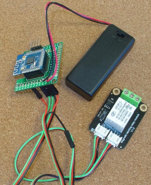
DFROBOT Version
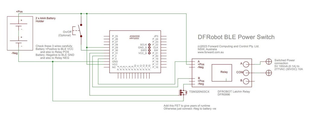
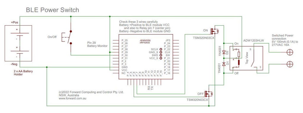
The circuit for the DFROBOT version is trivial (pdf version)
The FET disconnects the DFROBOT Latching Relay (module schematic) when not being switch. If you omit the FET and just connect the -Neg lead to the battery negative then the relay module will draw ~1.5mA continuously. This reduces the battery runtime to ~1month for AAA batteries and ~2months for AA batteries. If you add the FET, see Mounting the FETs, below, for how to mount it on veroboard.
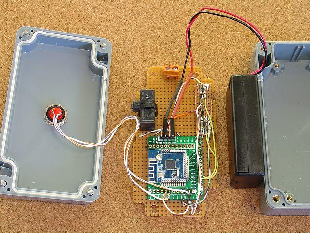
Above is a sample construction without the FET. Using 11 x 0.1' Male Header Pins (DFROBOT FIT0048 ~US$2.90)
Note the RED lead from the relay module plugged into P0.29 to supply the VCC voltage input to the ADC to measure the battery volts.
Upload the DFRobotPowerSwitchComplete.ino sketch to the BLE module to complete the construction. That sketch includes support for driving the FET via P0.31 and a manual pushbutton via P0.30.
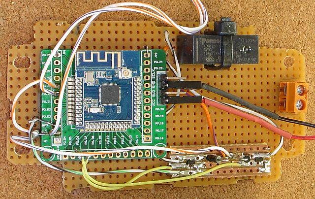
Panasonic Latching Relay Version
The schematic (pdf version) is trivial, except for mounting the very small FETs (see below)
As is the wiring diagram (pdf version)
The construction is done using a small square of veroboard for mounting the fets and diodes and the rest of the components were mounted on unclad (no tracks) punched laminate. Note the tie wrap securing the relay to the mounting board. If you are using veroboard for mounting all the components be sure to clear ALL the copper under the relay between the three (3) drive pins and the two (2) switch contact pins maintain the separation between the low voltage BLE circuit and the switched voltage.
Upload the PowerSwitchComplete.ino sketch to the BLE module to complete the construction. (See below for how this sketch was generated).
Low Power Switch (<24V / <2A)
The Low Power Switch is even simpler (pdf version) and uses the LowPowerSwitchComplete.ino sketch.
Step 2: Mounting the FETs
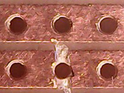
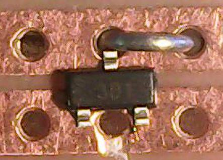
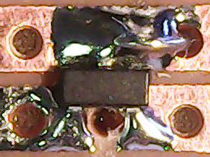
The small FETs can be mounted on veroboard as shown in the photos below. These FETs are very small and inexpensive so order extras for when you loose them on the floor.
Cut one track through hole.
Add wire to fill in the hole so the solder will bridge the gap and position the FET
Tack one leg of the FET with solder to keep it in place and then finish soldering all the legs.
Step 3: Generating the BLE NRF52832 Low Power Code
The generated code from pfodDesignerV3.txt is PowerSwitch.ino. The final code with the debounced manual pushbutton, low power ADC, low voltage cutout and a toggle on/off cmd is in PowerSwitchComplete.ino
The free pfodDesignerV3 Android app allows you to design a menu of buttons that will pulse specified output pins to switch the Latching Relay On and Off. The Pulsed Outputs for Arduino tutorial shows you how to use pfodDesignerV3 to create a menu for you Android mobile with buttons that will pulse an output. In this case there are two buttons, one for ON and one for OFF and the pulse length is high for 100ms (0.1sec). The relay specification is minimum pulse length of 15ms and Panasonic recommends a pulse length of at least 5 times the minimum, i.e. 75ms so 100ms (0.1sec) is good.
The pfodDesignerV3 can also generate code to read and display ADC reading scaled to real values. See How to Display/Plot Arduino Data on Android using pfodDesignerV3 / pfodApp for a tutorial. Here the battery is connected to Pin 29 and read by the ADC. The count is sent to pfodApp which scales it to 0 to 3V and displays the reading.
pfodDesignerV3 creates simple menus and sub-menus and charts. You can also use pfodGUIdesigner to create fancy GUI components with touch zones (active areas on the screen) and then generate test code for a variety of boards, including the nRF52832. See the pfodGUIdesigner tutorial for examples.
The generated code from pfodDesignerV3.txt was pasted into PowerSwitch.ino. In this code the ADC is read every 1sec for testing. Compiling this code and loading it onto the nRF52832 bare module gives the first working version of the Power Switch.
Step 4: Using PfodApp and Nordic NRF Toolbox to Control the Power Switch
Using pfodApp to control the Power Switch
Program the BLE module with the PowerSwitch.ino sketch. If you have installed the pfodApp on your Android mobile you can now setup a connection to the Power Switch which will display the designed menu when it connects. All the menu definition is contained in the Arduino code, the pfodApp just displays it. So the same pfodApp can connect to different devices each displaying their own user interface.
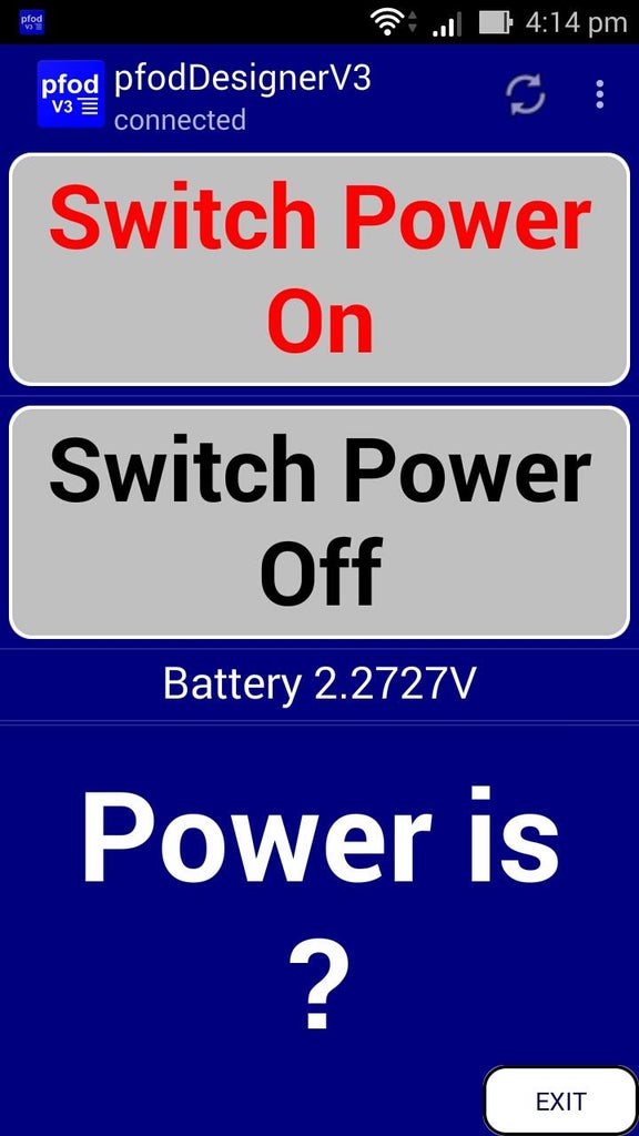
Opening pfodApp and connecting to the Power Switch displays this designed menu.
Pressing the On/Off buttons control the switch. Looking at the debug screen via the top right context menu, shows the commands being sent received. You can also read the command from the sketch. All commands and responses are enclosed in { }
{A`1} turns the switch ON, {B`1} turns the switch OFF. (The `1 starts the high output pulse, sending A`0 would terminate the pulse if it was still active.)
Using Nordic nRF Toolbox to control the Power Switch
If you don't want to use pfodApp, or you want to use an Apple iOS mobile, you can control the Power Switch using Nordic's nRF Toolbox (Android version) (Apple iOS version). In the latest version select the Utils services – UART service and select the pfod BLE device to connect to. Once it connects choose Macros, create a new configuration and define two keys to send the ON {A`1} and OFF {B`1} command. Turn off the Macro editing and you can now send the On/Off commands. Using pfodApp is more convenient.
Step 5: Completing the Power Switch Code
The PowerSwitchComplete.ino contains the final code for the Power Switch. The extra software added is :-
1. A manual override pushbutton using the Low Power Button Debounce.
2. Low power non-blocking ADC to replace the normal blocking ADC. The ADC now checks the battery voltage every 60 secs.
3. A low voltage cut out that turns the relay off when the battery voltage falls to 2.4V and prevents it from turning on.
4. A toggle cmd, {T}, that will toggle the relay On/Off. This will be used by the one-button remote control.
5. Request pfodApp menu updates every 10sec to pickup manual overrides or low voltage OFF switches.
When the circuit is powered up, with the 2 x AA batteries, the software assumes the relay is in the ON position. (PowerOn flag is true). If the startup() ADC reading detects the battery voltage is low then having PowerOn true on startup will trigger the Off coil to turn the relay off. To synchronise the software PowerOn setting to the relay contact state, just press the manual override push button after changing the batteries.
See the PowerSwitchComplete.ino code for the details. LowPowerSwitchComplete.ino is the complete sketch for the Low Power Switch. . DFRobotPowerSwitchComplete.inois the completed sketch for the DFROBOT verison.
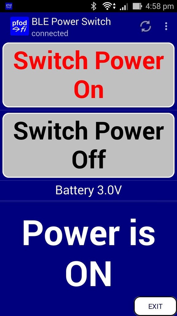
The final pfodApp menu is shown above
Step 6: BLE Module Current Usage
NOTE: If your supply current is not as low as you would like/expect, check that
a) the SWD/SCLK cables have been removed
b) the board has been power cycled
c) Serial.begin() has NOT been called
d) the TX/RX serial cables are removed
The measured current for this circuit is ~60uA Advertising and ~50uA Connected and updating the pfod menu every 10secs. So for 2 x AA Alkaline battery (energiser_AA_alkaline_e91.pdf) running down to 1.2V is ~2105mAhrs (approx 40/57 x 3000mAhr) => 4years when Advertising and longer when Connected.
To switch the relay requires 133.3mA (less as the battery voltage declines) for 0.1sec => 3.7uAhrs (0.0037mAhrs) each time it switches. That is 2 switches a day for 4 years uses ~11mAhrs of the battery power and so ignorable.
Since the connected current consumption is less than the advertising current, there is no downside, battery wise, to keeping the BLE connected all the time to say a WiFi to BLE bridge. Note: Coin Cells like the CR2032, apart from having less capacity, are not suitable due their relative high internal resistance, typically 10ohm initially and rising as the cell discharges. At 107mA at 2.4V required to drive the relay coil, the internal resistance of a new CR2032 drops the cell's voltage by 1.07V to ~2V which is less than the 2.4V required to switch the relay.
Step 7: Single Button Remote to Control of the Power Switch
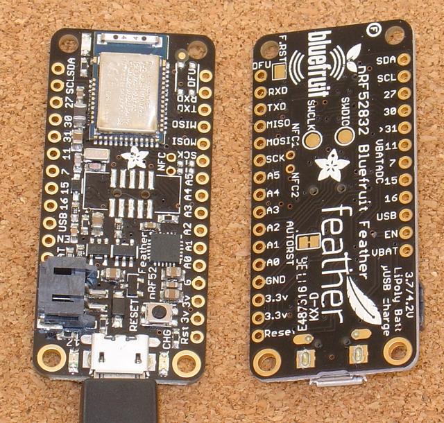
A trivial one button remote control can toggle the Power Switch on/off. It uses an Adafruit nRF52 Feather board (~US$24) programmed with the PowerSwitch_remote.ino sketch. Each time the board starts up it scans for the MAC of the Power Switch and then connects, send the toggle cmd, {T}, and disconnects.
To make the one button remote just insert a momentary push button in series with one of the Battery power leads so that the board starts up/runs only while you are pressing the push button.
You need to update the
const char Client_MAC[] = "F5:FA:14:1C:85:B7"; // <<<<<<<<< this must match the MAC of your Power Switch BLE at the top of PowerSwitch_remote.ino sketch to match your BLE module's MAC address as seen in the Nordic nRF Connect app.
The downside of the this trivial one-button remote is that while it typically only takes a few secs to work, it can take upto 10sec to scan, connect and toggle the Power Switch. There is not visual feedback on the remote. It is assumed you are in sight of the Power Switch's output so you can see it turn on/off. The PowerSwitch_remote.ino sketch could be updated to parse the response from the Power Switch and turn of the appropiate led to indicate the Power Switch's state.
Step 8: BLE Sensor Controlling the Power Switch

A remote sensor, such as a light level sensor can be used, via a BLE to BLE bridge to control turn the Power Switch on at night and off in the morning.
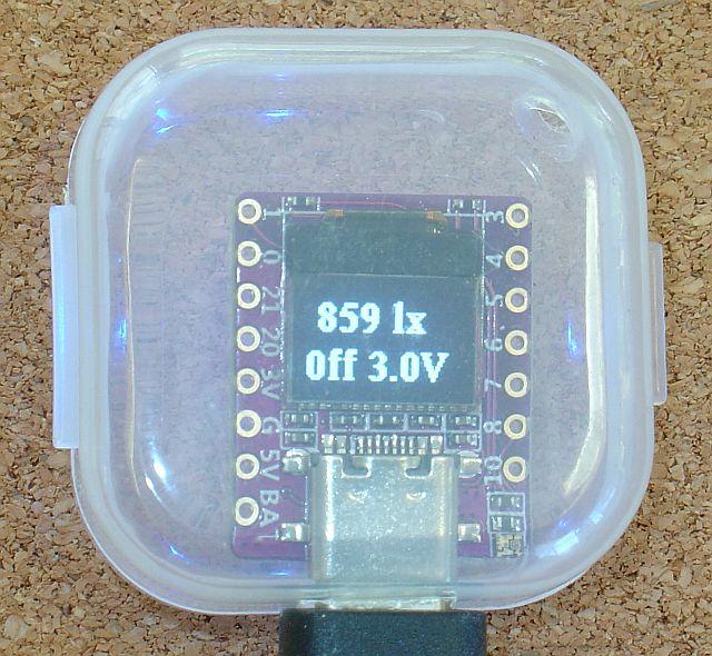
The top line of the display is the current Lux reading. 10 lx is the transition between day and night. The bottom line displays the current state of the Power Switch and its battery volts.
Parts List:
ESP32-C3 – 01Space ESP32-C3-0.42LCD (~US$7.30 from aliexpress, programmed with board setting Adafruit QT PY ESP32-C3)
Also tested with with Sparkfun ESP32-C3 (~US$9 programmed with board setting ESP32C3 Dev Module) and Adafruit QT Py ESP32-C3 WiFi Dev Board with STEMMA QT (~US$10 programmed with board setting Adafruit QT PY ESP32-C3) Programmed using the ESP32 V2.0.6 Arduino board support.
BLE Lux Sensor: With this project in mind, the outdoor BLE weather sensor (WL_1) included a Lux sensor (BMD820)
Construction:
The 01Space ESP32-C3-0.42LCD came in a little plastic box. Cutting a slot for the USB-C cable and adding some ventilation holes made a case that could be mounted with double sided tape. Programming with the sketch and files in LuxToPowerSwitch.zip (needs ESP32 V2.0.6, the SafeString library V4.1.25 and U8g2 by Oliver library V2.33.15) completes the construction.
Note: The 01Space ESP32-C3-0.42LCD is programmed using the Adafruit QT PY ESP32-C3 so that the Serial debug works.
Note: The ESP32-C3 chip gets hot. Some 30degC above ambient. So add ventilation holes to any mounting case.
Note: The 'chip' antenna on 01Space and Adafruit QT PY boards is less effective than the Sparkfun ESP32-C3 printed track antenna. The 'chip' antenna to Power Switch connection distance is about 9m and more than 10m for the BLE sensor broadcase. The printed track antenna gets approximately +20 rssi over the 'chip' antenna which translates into more than double that distance.
There are a number of ways a sensor can be used to control the Power Switch. Here an ESP32-C3 is used to open a BLE Nordic UART connection to the Power Switch using it MAC address as read from Nordic nRF Connect. The ESP32-C3 BLE scanner is configured to continue to run and read the advertised lux light level from the WL_1 – Temperature, Humidity Sensor, Barometric Pressure and Lux level Sensor. The sunrise/sunset lux level of 10 is then used to turn the Power Switch on at sunset and off at sunrise. The advantage of using advertising BLE sensors is that you don't need to connect to the to get the readings and they can advertise to multiple systems. In this case the WL_1 sensor is used by both the Power Switch and the Weather Station.
The lux control only triggers the Power Switch at sunrise/sunset. There is a 10min dead time after each trigger to prevent transient triggers. At other times the manual pushbutton can be used to override the Power Switch setting.
Here is a minimal debug output. This same sketch can be used for all three boards. The boards without the LCD just send the LCD data to no where.
Starting LuxToPowerSwitch...
---- lx
----- V
Found Power Switch F5:FA:14:1C:85:B7 rssi:-83
---- lx
----- V
Connecting ... connected to the BLE Server.
Sending '{.}'
Power is OFF  Battery 3.00V
---- lx
0ff 3.0V
Sending '{.}'
Power is OFF  Battery 3.00V
---- lx
0ff 3.0V
WL_1 Temperature:21.1C RH:72% Barometer:1008.9 hPa Lux:159 lx
Found Sensor: WL_1,21.1,72,1008.9,159 rssi:-73
Sending '{B`1}'
 159 lx
0ff 3.0V
Power is OFF  Battery 3.00V
. . .
The LuxToPowerSwitch sketch include a number of error checks and timeouts. If the board can not make a connection the display (and debug output) show “----- “ missing data. The sketch also as watch dog timer in the loop() code because the ESP32-C3 can lock up in the BLE code on internal errors.
The LuxToPowerSwitch maintains a continuous connection to the PowerSwitch which prevents using a remove override. The sketch could be modified to only connect at sunrise/sunset when the PowerSwitch needs to be triggered, but that takes more logic and the ESP32 sometimes locks up on trying to create a BLE connection. An alternative is to add a WiFi connection that can be used to control the PowerSwitch on/off state.
Step 9: Controlling the Power Switch Via WiFi PfodApp

You can use a WiFi to BLE bridge to control and monitor the Power Switch via WiFi, while maintaining the sensor control.
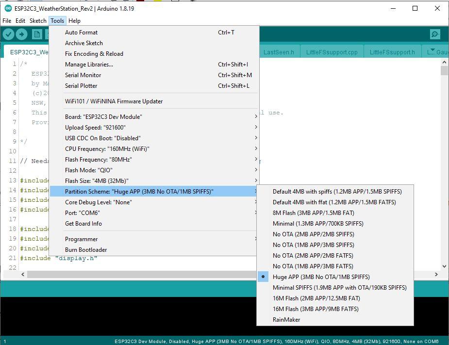
Using the same board as was used above for the LuxToPowerSwitch. Set the ESP32 Partition to Huge APP
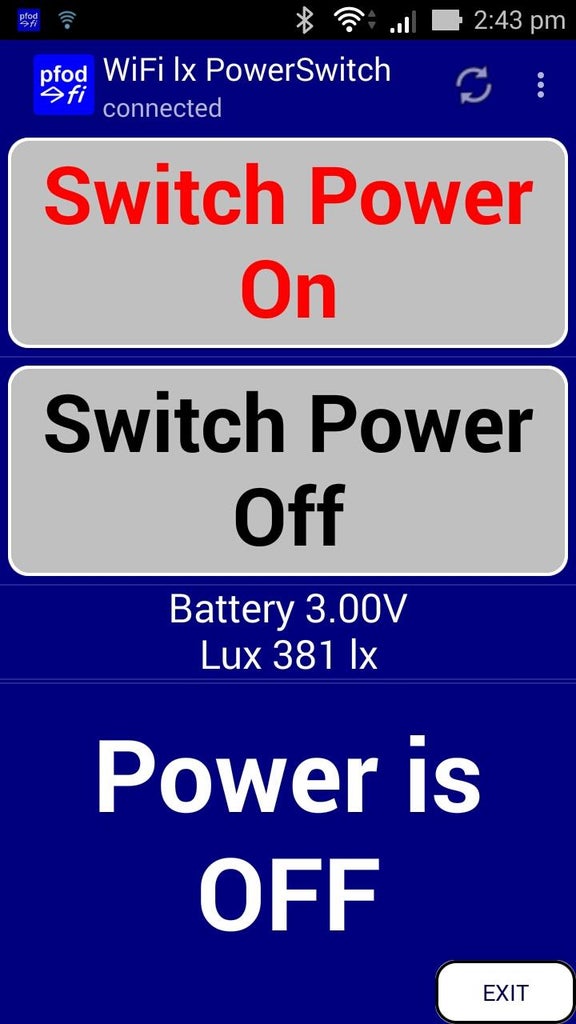
Then unzip WiFiLuxPowerSwitch.zip [https://www.forward.com.au/pfod/BLE/PowerSwitch/WiFiLuxPowerSwitch.zip] and upload the WiFiLuxPowerSwitch.ino sketch to your ESP32-C3 board. This sketch runs both a WiFi server and a BLE Client at the same time. Connecting pfodApp to the WiFi IP address, (e.g. 10.1.1.71:2989) displays the screen above which lets you monitor the Lux level, Battery Voltage and Switch state (on/off) as well as override the Power Switch on/off state.
You could also add an NTP client so that you could switch the Power Switch on/off as specified times.
Step 10: Design Considerations
This section covers some aspects of the design. The design was driven by the availability of an inexpensive low power BLE module that would run for years on a small battery together with the availability of a latching relay that can switch 277VAC at 16A and that can be operated by a 3V supply
The BLE module
A low power BLE module is needed for long battery life. That is one without any extra components. No power regulators, extra sensors etc. There are a number of such BLE modules available. Here the an nRF52832 base module was used because a previous project provides low power Arduino programming support for this chip. Suitable available nRF52832 'bare' modules include:- XL52832-D01 module (and Jessinie nRF52832 Adaptor board), the GT832E_01 with less pins and the Adafruit nRF52832 Bluetooth Low Energy Module – MDBT42Q-512KV2. The XL52832-D01, plus adaptor board, and the GT832E_01 are easier to mount on 0.1” veroboard so they were used to avoid the time and cost of making a PCB.
The Relay
The relay latching is important as it means no power is consumed while the relay of operated. The 277VAC rating covers the 240VAC supply used in Australia and similar voltages used in many other countries. The standard power point current rating at 240VAC is 10A giving 2.4KW power for heater etc. The 16A rating of the relay covers the power requirements of countries that use 110-125VAC (e.g USA) and similar voltages. Because this voltage is lower, more current is needed to get the same power. Typical power point current ratings at 125VAC is 15A giving 1.875KW for heaters etc. (NEMA 1-15 ungrounded (Type A) and NEMA 5-15 grounded (Type B). Both Australia and the US (and other countries) have higher rated wall sockets e.g 20A etc. but the common household appliances sockets are 10A (for 240V) and 15A (for 110V) respectively.
The Panasonic ADW1203HLW latching relay has 3V coil version and a 277VAC / 16A contact rating. The dual coil version was chosen to simplify the driving circuit. The coils take 133mA to operate and so need a transistor/fet to interface between the BLE module pin (maximum 10mA in High Drive mode) and the relay coil. The dual coil common pin is the plus pin so the coils need to connected to ground to switch the relay. Transistors could have been used but that would require two extra base resistors so FETs where chosen instead.
The driver FETs
FETs are used here to avoid adding the additional resistors need for transistors. (Note: For optimal switching small gate resistors are used) FETs often/usually have a bias gate resistor to ensure the FET is not turned on by a build up of stray charge on the gate. Those resistors are also dispensed with here and the BLE module driving pin is used to provide a hard ground for the FET gate to keep it turned off. There can be transient FET turn-on when the circuit is powering up, before the BLE module pin is set as an output and switched to LOW, but that can only happen every 4 years or so when the batteries are changed.
Having decided to use FETs to drive the relay coils, suitable and available FETs needed to be selected. The component search function of electronic component suppliers like Digikey, Mouser, Element14 etc and be used for this. The main requirements are an FET. N-Channel, In stock, with a low On resistance when driven by 2.4V gate drive. So the Vgs (th), the Gate-Source thresh hold voltage must be well below 2.4V so that the FET is switched on hard by a 2.4V gate drive. So say Vgs(th) less than 1V. The On resistance also needs to be low because the 2 coil 3V latching relay coils are only 22.5 ohms. So a 2 ohm FET Rds (ON Reistance Drain-Source) will reduce the voltage on the coil by 10 percent. A FET with an Rds of less then a few tenths of an ohm is desirable. So say less than 250milliohms (0.25 ohms) maximum Rds, Then you can filter by case style. Here an SOT-23 / SOT-23-3 case was specified and that limited the results to 5 items :- ZXMN3B01F, FDN337N, TSM320N03CX, DMN3300U and DMN3200U.
The BLE module runs from 1.7V to 3.6V, but the relay has a minimum coil activation voltage of 2.4V so the low voltage turn off was set at 2.4V. With 2.4V available to drive the FET, any of the 5 FETs can drive the relay coil. The TSM320N03CX was chosen because it has a very low On resistance which makes it a better choice for the Low Power Switch (see below).
The relay driver FETs are required to carry the coil current of 133mA without exceeding the maximum junction temperature. As discussed below, the SOT32 cases can handle this current with a suitable gate drive.
Flywheel Diode
When the relay coil is turned off its magnetic field collapses and generates a current flowing in the same direction. The coil produces a voltage sufficient to drive this current. Without the flywheel diode to conduct the current, the generated voltage is a very large spike. The flywheel diode need only be a general purpose diode capable of currying the coil current, 133mA and with a reverse voltage that exceeds the supply voltage. 1N4001/4 are suitable general purpose 1A rectifiers with 35V (1N4001) / 400v (1N4004) reverse voltage.
Low Power Switch
The 'standard' Power Switch uses the latching relay. The relay contacts are rated for 5VDC/100mA to 277VAC/16A. At low voltages and low currents, there is insufficient “wetting current” to break down the surface film resistance of the contact and the relay will appear to be open even when operated. For Panasonic ADW1203HLW the minimum load to be switch is specified as 5V / 100mA. For controlling lower DC voltages and/or lower currents, the relay can be replaced with a FET. Because the Vgs voltage is supplied by the BLE module and is completely independent (floating) of the voltage being switch, you can use this to switch any DC voltage and current the FET can handle. The Vds breakdown voltage of the 5 FETS are all 30V so that limits the maximum voltage that can be switched.
The TSM320N03CX needs has a much lower On Resistance (max 40mOhms at 25degC ambient with a 2.5V gate-source voltage) than the other FET considered and so can carry more current without overheating. See the Power Handling calculations below.
SOT23 Power Handling for the Low Power Switch
The Low Power Switch is specified for switching less then 24V and 2A. Need to check the FET will not melt caring the 2A. All the FETs have an SOT32 case. With minimal pads the Junction to Ambient thermal resistance is ~250C/W (an-1025.pdf). So for 80degC ambient and max junction temperature of 150decC (150-80)/250 = 280mW dissipation.
The TSM320N03CX with a 2.5Vgs has an On resistance of 0.04ohm (max at 25degC) and ~1.8 x 0.04ohms at 150degC junction temperature => 0.0.72ohms. So for a 2A load current the dissipation is ~144mW which is well within the 280mW maximum above. At 2.4Vgs, the On resistance will be only slightly higher, so the turn off voltage limit for the Low Power Switch was left at 2.4V.
Low Power Switch Reverse Voltage Protection
All the FETs have an un-avoidable, a parasitic diode in their construction, visible in their schematic symbol. If the polarity of the external wires connected to the Low Power Switch are reversed the load current will flow through this parasitic diode and the switch will just appear to always ON. However the forward voltage of this parasitic diode is usually relative large for a diode, about 0.65V at 0.5A/85degC. For small currents this is not a problem but for the 500mA maximum specified current, the results in ~0.33W dissipation, which exceeds the estimated maximum power handling of the SOT23 case (above). A simple way to avoid the problem and protect the FET from thermal breakdown when the voltage is reversed is to prove an alternative path for the reverse current but adding a parallel Schottky diode. For example a 3A B330 Schottky diode has reverse voltage rating of 30V and forward voltage that is less than the FET diode voltage at all temperatures so the reverse current preferentially flows through the Schottky diode instead through the FET parasitic diode.
However Schottky Power diodes have a downside of relatively high reverse leakage, e.g. B330 has a reverse leakage current (at 30V Vds) 0.1mA at 25degC ambient and 20mA at 100degC ambient. This compares to only 1uA (0.001mA) at 25degC Ambient temperature for the TSM320N03CX. It is a design choice as to whether this Off leakage is acceptable for the reverse polarity protection.
For this design of the Low Power Switch, a reverse voltage protection diode was not added.
Step 11: Conclusion
The BLE controlled Power Switch is very simple to construct and can control all household devices from 5V USB (100mA) loads to 15A space heaters. For switching low power DC loads, as simpler version was also presented that handles up to 24V DC and 2A. The remote control can be via pfodApp (BLE) or Nordic nRF Toolbox or via a BLE sensor using an ESP32-C3 BLE to BLE bridge or via a WiFi connection using a ESP32-C3 WiFi to BLE bridge.
The article was first published in Instructables, April 15, 2023
cr: https://www.instructables.com/Very-Simple-BLE-Power-Switch-for-Beginners/
author: drmpf


