Just the other day, I was in the middle of a very important phone call when my banana phone stopped working! I was so frustrated. That’s the last time I miss a call because of that stupid phone! (In hindsight, I may have gotten a little too angry in the moment, see pics)
It was time for an upgrade. Enter the wireless tin-can telephone! The all new and improved gag phone, for all my fake communication needs!
Note: (This project does actually work)
Here’s how I built it!
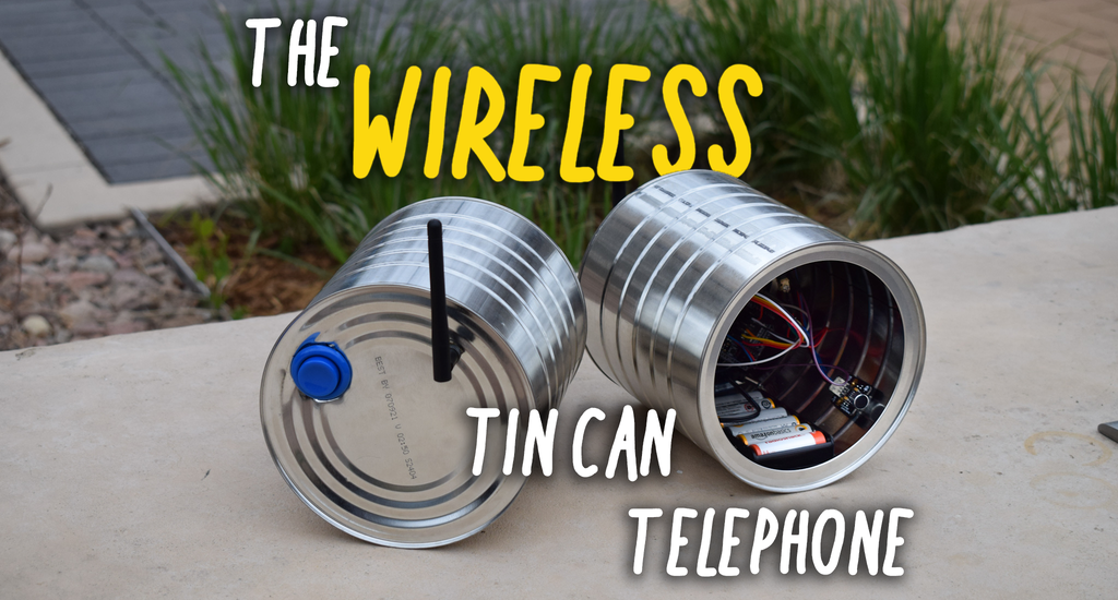
Step 1: Tools and Materials
For this project, you’re going to need quite a few electronics, and a couple tools.
I'd like to disclose that this project was sponsored by DFRobot. All of the parts were provided by them, and some of the links provided are affiliate links to DFRobot. Feel free to use them if you would like to support Facio Ergo Sum! Off-brand parts work as well. Thanks to DFRobot for making this project possible!
Tools
- Drill (w/ Bits) - Tin Snips - Hot Glue Gun (Careful: Very Hot) - Needle Nose Pliers - Ball-peen Hammer
Step 2: Prepping the Cans
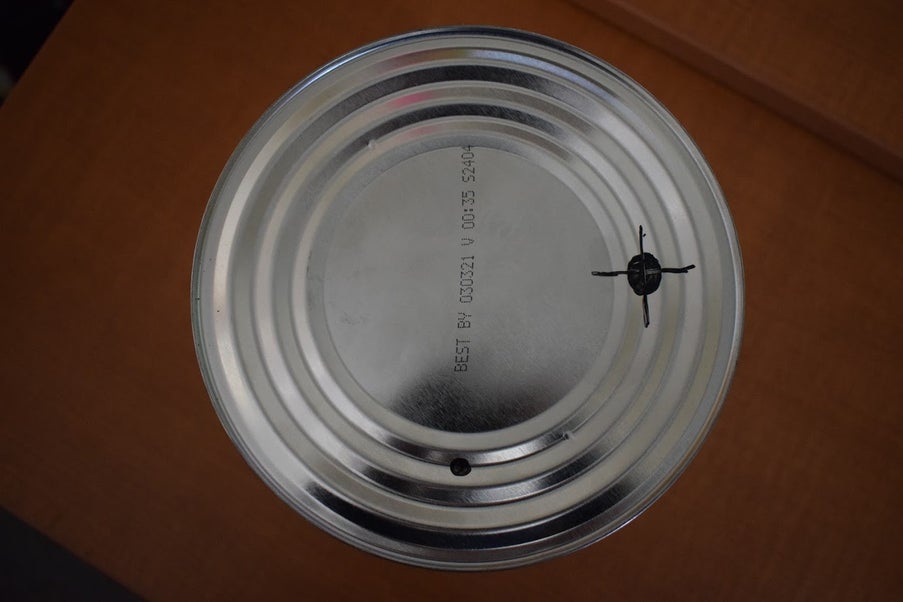
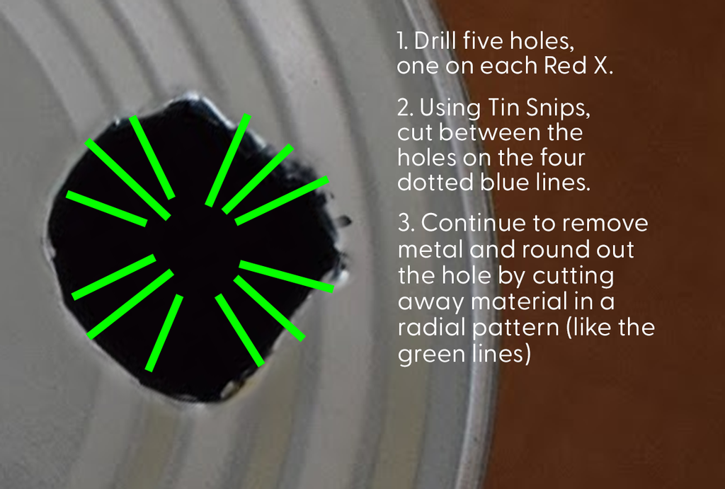
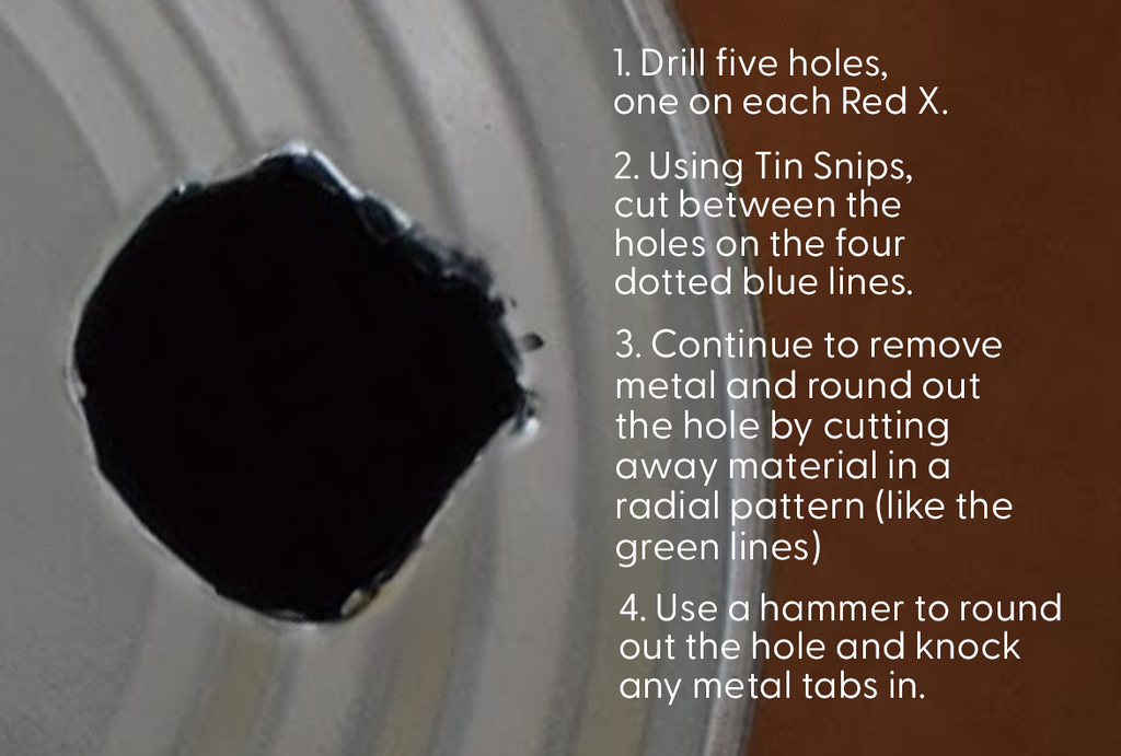
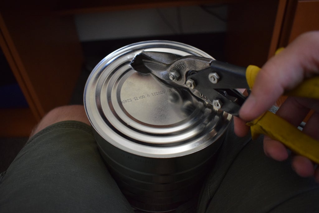
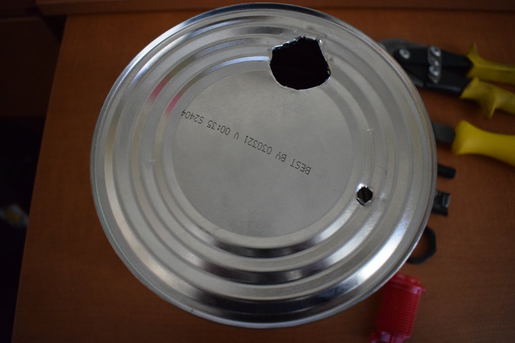
Before we can wire up the electronics, we’ll need to prep the cans. To do this, we will be drilling two holes, one for the antenna, and one for the button.
I started with the antenna hole. First, I placed the antenna board inside the tin can, to measure how far from the side the hole would need to be. Then, using my finger to note the ridge, I marked the hole with an Whiteboard marker, so that I could wipe them off later. Then, using a tap, I put a small indentation where I was going to drill. This will help guide the drill in the next step.
Depending on the antenna you use, you may need a smaller/larger hole. So what I did to find the right size, was compared the threads on the antenna to the drill bit sizes.
Note: (Mine ended up being 7/32)
Alright, SAFETY GLASSES ON!
Once you’ve picked a size and marked out the hole, drill into the can, go at a high speed, but don’t push too hard. Because of how flimsy the tin can is, it will usually shear, so watch for sharp metal. Use tins nips and pliers to clean up this edge.
Then it’s time for the button hole. This one’s a little different.
Note: I’m working with what I have, so I decided to attempt it using the drill and tin-snips again. A Forstner bit might work much better. Here’s how I did it.
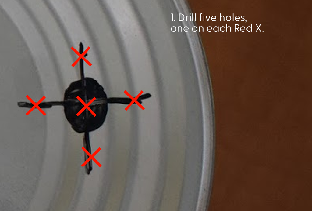
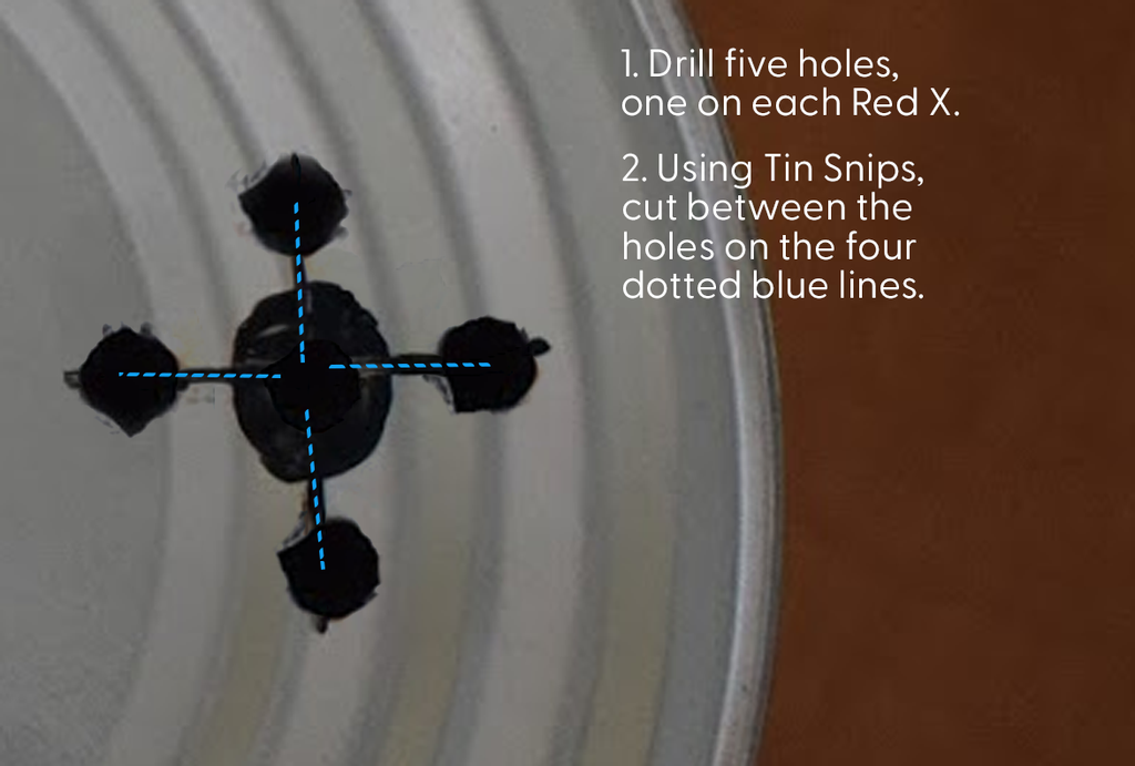
First, I unscrewed the plastic “nut” from the button. Then I placed the nut onto the location I wanted the hole, and marked the inside diameter. Then I drilled five holes, and used tin snips to clean the material out and form it into a circle. Mark the hole, tap it, and drill.
STOP! It's HAMMERTIME!
After this, I used a hammer and pliers to knock in the metal tabs and bend them down. Please refer to the images for a better idea of how I did this. I’ve provided a shoddy diagram that should be able to help you out.
Note: I suggest using a ball-peen hammer. I used a regular hammer because that’s all I had.
Once that’s done, you can screw in the antenna and the button. Again, be careful of any sharp metal bits!
Step 3: Hot Glue Gun Time!
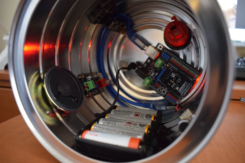
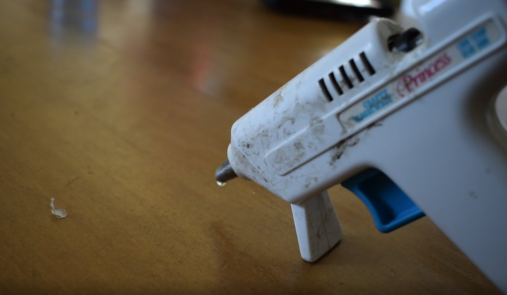
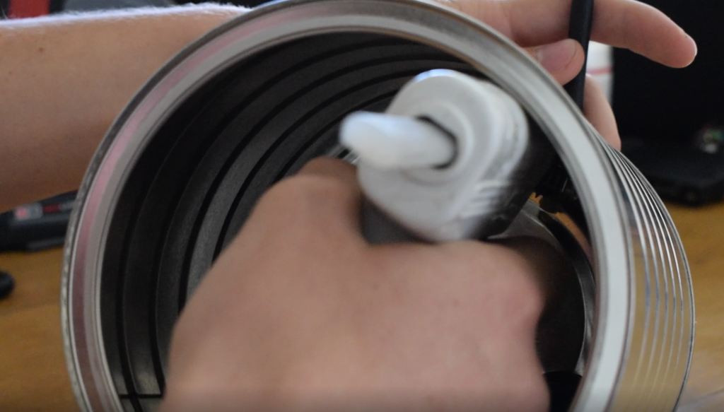
Now let’s glue in the components!
First, plug in your hot glue gun and wait for it to heat up.
*Jeopardy theme begins to play...*
Then, use hot glue to secure the antenna board against the can. I also suggest coating the metal part of the antenna that sticks through the can with glue, so it won’t ground out to the can.
Note: With all of these components, use copious amounts of hot glue, so nothing has the chance of grounding with the can. If you hear a buzzing or beeping noise when testing it, you probably have a ground fault.
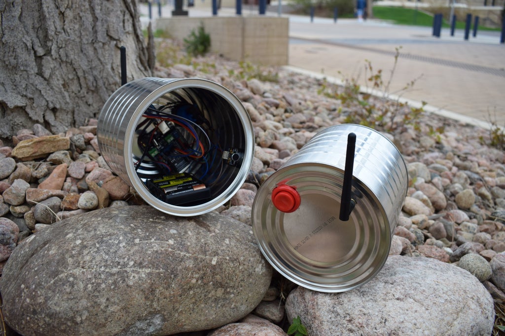
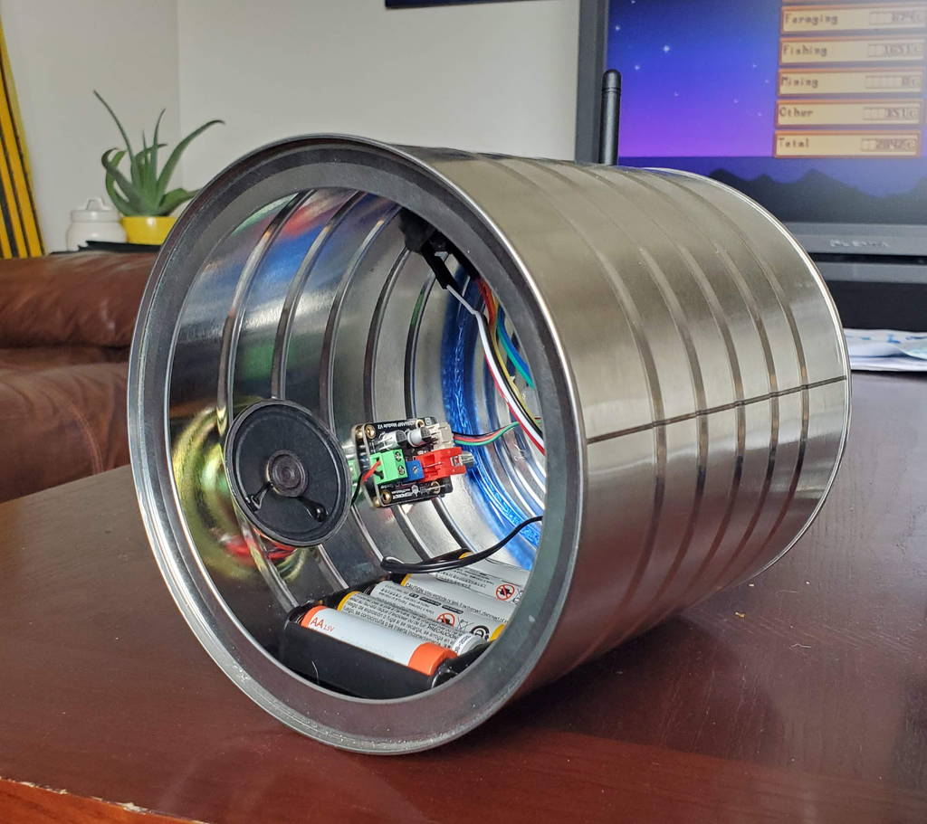
Glue the Arduino Uno to the bottom of the can, and then attach the battery pack. This will be the heaviest part, I suggest apply glue to the edges and then placing it where you want the can to rest (so the antenna points upwards). The battery pack will always be the natural center of gravity for the can.
I glued the speaker on one side of the battery pack, and the microphone on the other. (Refer to the pictures) This was primarily for aesthetic purposes, and wire management.
Make sure to use lots of glue so that none of the pins ground to the tin can.
Step 4: Wiring the Circuit
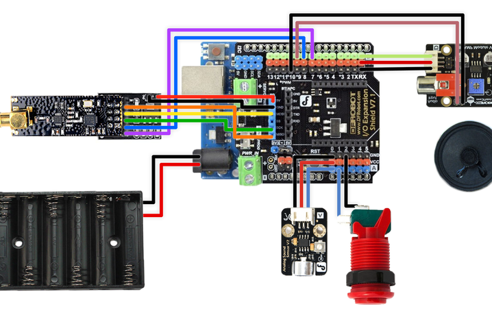
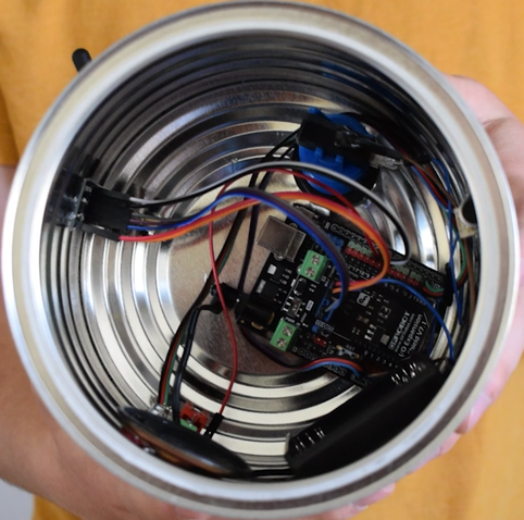
Once everything is securely glued in, it’s time for wiring! Use the provided schematic to connect all the jumpers to their appropriate pins. I’ll also provide the pin-outs below:
(Note, this is for the Gravity Expansion HAT)
Antenna Board:
- MI -> MISO - MO -> MOSI - SCK -> SCK - CE -> Pin 7 - CSE -> Pin 8 - GND -> GND - 5V -> 5V
Something to note about this board. The NRF24L01 is a wonderful piece of technology, but very sensitive to electricity. Make sure to only power it with 3.3V unless you are using the included backpack like I am. ONLY CONNECT TO 5V WHEN USING THE EXTRA BOARD, otherwise it will fry the antenna.
Analog Sound Sensor:
- Gravity Pins -> A0
Audio Amp:
+(on the speaker input) -> 9 or 10 (left or right audio)-(on the speaker input) -> GNDGravity pins -> D0Switch:
- NO -> A1 - COM -> GND
Here’s a brief explanation of the circuit (to hopefully benefit anyone using a different board).
Because of the RF24Audio Library we are using, there is a very specific pinout for the microphone, speaker, switch, and antenna:
The Microphone signal pin will always go on A0 pin.
The Switch (for switching to transmission mode) is always the A1 pin.
The Audio Amplifier I’m using doesn't matter where it’s plugged in, as long as it has power. What matters is the wire you are using for audio transmission, which by default will be pins 9 and 10 (for left and right audio).
The Antenna pins CE and CSE are always connected to pins 7 and 8 respectively (which is what allows both directions of radio signal)
Hopefully this information will help you wire this circuit on any board.
Step 5: Pushing the Code
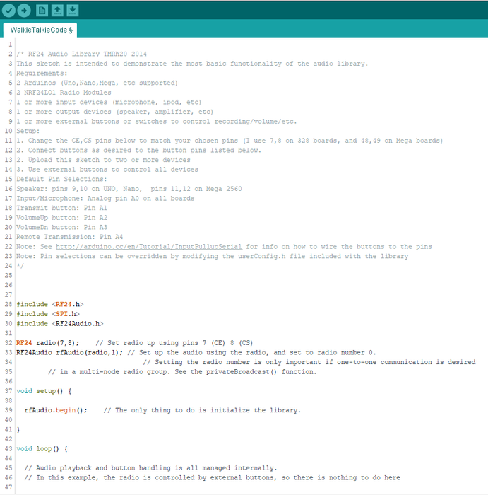
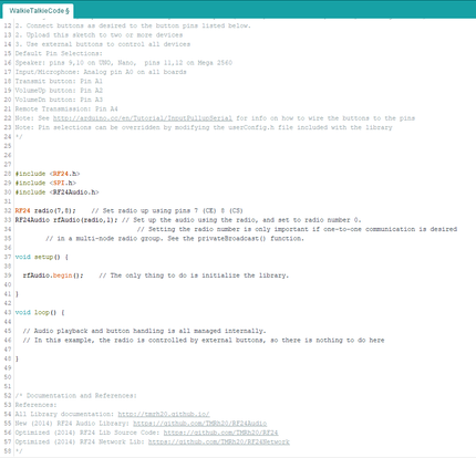
It's time to push some code! The program for this project is SUPER simple thanks to the RF24Audio Library. It’s literally not even 10 lines of code! Take a look:
//Include Libraries
#include <RF24.h>
#include <SPI.h>
#include <RF24Audio.h>

RF24 radio(7,8);    // Set radio up using pins 7 (CE) 8 (CS)
RF24Audio rfAudio(radio,1); // Set up the audio using the radio, and set to radio number 0.

void setup() {
  rfAudio.begin();    // The only thing to do is initialize the library.
}
I won’t be explaining how it works here, but if you’d like to learn more about Arduino IDE and what this code means, check out this link.
You'll also need to install the RF24 and RF24Audio Library as well, which you can download here.
Once you’ve got the Arduino IDE installed, download the Arduino program provided, and open the code. Look under the Tools drop-down. Make sure “Programmer” is set to AVR ISP, and Board is set to Arduino UNO (or whatever board you are using). Also confirm that you are on the right Port (it should say “Arduino Uno on COM#”)
Now we are ready to push the code. Plug in a USB cable to the Arduino and the computer, and click the Upload arrow in the top left of the IDE. The code should upload and you may hear a quiet buzz.
Try pushing the button and see if the buzz changes pitch. It should also dim an LED on the top of the IO Expansion HAT.
If you are getting these results, then the program should be running correctly and everything should be connected the right way.
Step 6: Testing It Out




To test it out, you’ll need to turn both cans on. Press the button down on one can, and make some noise into the microphone. Can you hear audio coming from the other can?
Try the same thing on the other can. Hear anything?
If so, it works and you’re done! Note: If you’re getting interference or buzzing, check for grounding problems. Make sure none of the leads are touching the can, and that there’s plenty of glue between components. Try to avoid twisting around each other, as this will increase interference. I also suggest covering the metal part of the antenna with electrical tape to prevent it from grounding to the can.
Once you know it works, try to test the distance too; it should go up to a kilometer if there’s nothing blocking the signal!
Step 7: Conclusion
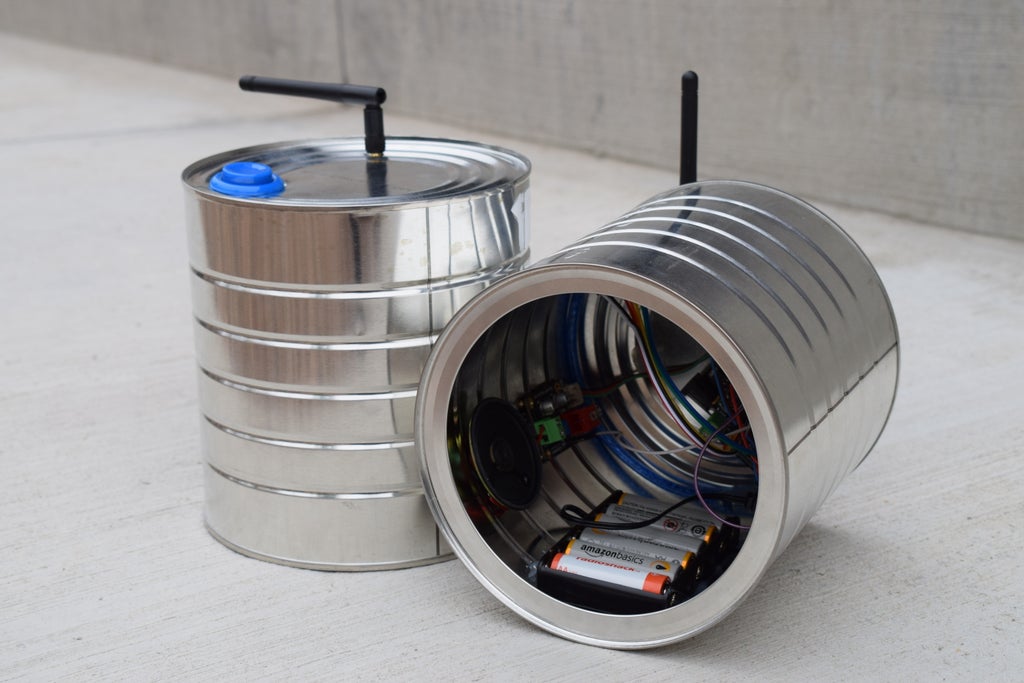

Congratulations, You’ve made it to the end! Awesome job building this project!
Thank you for reading my Instructable, I hope you enjoyed watching the video and I hope you found it very entertaining.
I’d like to disclose that this project was sponsored by DFRobot, they made it possible for this project to exist by supplying all of the parts, so feel free to go give them some love!
Update: I’m entering this Instructable in the Arduino Competition, so if you enjoyed this project, please give it a vote with the orange button down below!
UpdatedUpdate: I’m also entering the Arduino Make-From-Home Contest, so I’d love if you could go show me your support on those sites as well!
Updated Update on the Previous Update: I'm also in the Hackaday.io Making Tech at Home Challenge, so go vote for it here!
Follow me for more cool projects like this, and go make something! Always keep learning. :)
- Geoff M.
Facio Ergo Sum: "I make therefore I am"
The article was first published in Instructables
cr: https://www.instructables.com/How-to-Make-a-Wireless-Tin-Can-Telephone-Arduino-W/
author: Facio Ergo Sum


