
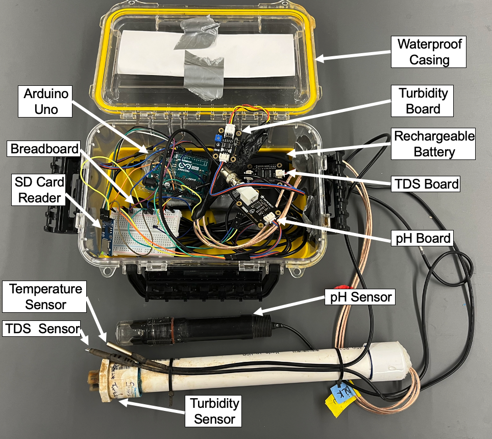
This guide will show you how to build, program, and deploy an environmental monitoring system that can monitor the Total Dissolved Solids (TDS), Temperature, pH, and Turbidity of a body of water and record the data to an SD card. This project has applications for both environmental monitoring of natural bodies of water and monitoring the water quality at a wastewater treatment plant. From our testing, the TDS, Temperature, and pH sensors work as expected while following this guide while the Turbidity sensor produces inaccurate results, which should be solved through further calibration and development.

- A 20,000 mAh USB battery pack: From our field testing, it appears that a new 20,000 mAh battery can power the assembled system for approximately one week. We used the Anker Portable Charger, 325 Power Bank (PowerCore Essential 20K): at first because it has a continuous power mode that doesn’t time out during an extended period of testing. While trying to make the project more affordable, we started suing lower cost 20,000 MAH batteries and have found that most 20,000 mAh batteries with good reviews on Amazon work.
- Waterproof Case: we used this one: But any waterproof case with dimensions around 11.1"L x 7.6"W x 4.2"H will work. If you are intending to use this system in a public area, we recommend using a black or camo case so it will be less visible.
- Micro SD Card – a weeks worth of data when the Arduino takes a reading every 5 minutes is less than 100 kb, so a large capacity card is not needed, 4gb is more than enough.
- Micro SD Card – a weeks worth of data when the Arduino takes a reading every 5 minutes is less than 100 kb, so a large capacity card is not needed, 4gb is more than enough.
- Arduino Uno
- SB Type A to Type B cable
- Breadboard
- Jumper Wires
- 4.7k OHM resistor
- 1 ft of 1†PVC pipe
- 1†PVC cap
- 1-1/4-in x 1-in PVC bushing
- 6 ft of 16 AWG Speaker wire
- Heat shrink tubing
- PVC Cement
- Silicone sealant
- Duct tape
- Flex tape
- Zip ties
Step 1: Software Setup
To program the Arduino, you will need to install the Arduino IDE. The latest version can be found at: https://www.arduino.cc/en/software
For the assembled sensor system to function, libraries for specific hardware pieces are required. For instructions on how to install an Arduino Library from a zip file, consult these instructions: https://docs.arduino.cc/software/ide-v1/tutorials/installing-libraries
For the DF Robot PH library use this link: https://github.com/DFRobot/DFRobot_PH/archive/master.zip
To install the latest version of the OneWire Library, which is used for the temperature sensor, use this link:
https://www.arduino.cc/reference/en/libraries/onewire/
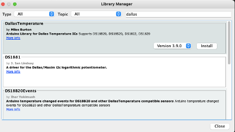
To install the Dallas Temperature library, open Arduino IDE and go to: Sketch > Include Library > Manage Libraries
Search for “Dallasâ€, and then install the DallasTemperature library by Miles Burton.
Step 2: Assemble PH Sensor Hardware
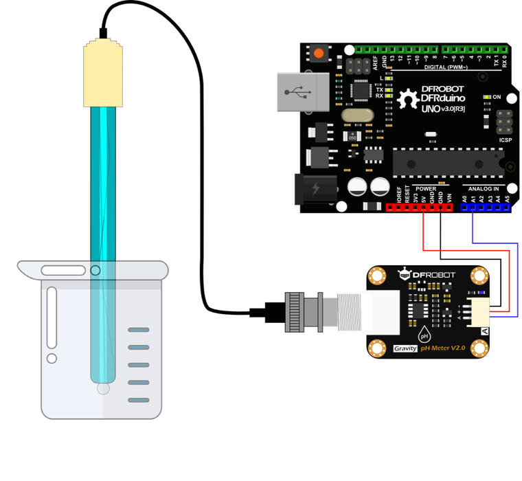
Before we can assemble the full system, we need to calibrate and test the pH sensor while it is the only sensor connected to the Arduino to prevent interference during the calibration process. Assemble the hardware as shown in the attached diagram and copy and paste the below code into the Arduino IDE or download the attached file.
/*!

 * @file DFRobot_PH_Test.h

 * @brief This is the sample code for Gravity: Analog pH Sensor / Meter Kit V2, SKU:SEN0161-V2.

 * @n In order to guarantee precision, a temperature sensor such as DS18B20 is needed, to execute automatic temperature compensation.

 * @n You can send commands in the serial monitor to execute the calibration.

 * @n Serial Commands:

 * @n  enterph -> enter the calibration mode

 * @n  calph  -> calibrate with the standard buffer solution, two buffer solutions(4.0 and 7.0) will be automaticlly recognized

 * @n  exitph -> save the calibrated parameters and exit from calibration mode

 *

 * @copyright  Copyright (c) 2010 DFRobot Co.Ltd (http://www.dfrobot.com)

 * @license   The MIT License (MIT)

 * @author [Jiawei Zhang]([email protected])

 * @version V1.0

 * @date 2018-11-06

 * @url https://github.com/DFRobot/DFRobot_PH

 */


#include "DFRobot_PH.h"

#include <EEPROM.h>


#define PH_PIN A1

float voltage,phValue,temperature = 25;

DFRobot_PH ph;


void setup()

{

  Serial.begin(115200);

  ph.begin();

}


void loop()

{

  static unsigned long timepoint = millis();

  if(millis()-timepoint>1000U){         //time interval: 1s

    timepoint = millis();

    //temperature = readTemperature();     // read your temperature sensor to execute temperature compensation

    voltage = analogRead(PH_PIN)/1024.0*5000; // read the voltage

    phValue = ph.readPH(voltage,temperature); // convert voltage to pH with temperature compensation

    Serial.print("temperature:");

    Serial.print(temperature,1);

    Serial.print("^C pH:");

    Serial.println(phValue,2);

  }

  ph.calibration(voltage,temperature);      // calibration process by Serail CMD

}


float readTemperature()

{

 //add your code here to get the temperature from your temperature sensor

} Step 3: Calibrate Per Detailed Instructions From DFRobot Pt 1
To ensure accuracy, the probe needs to be calibrated for its first use and after not being used for an extended period of time (once a month ideally). This tutorial uses two-point calibration and therefore requires two standard buffer solutions of 4.0 and 7.0. The following steps show how to operate two-point calibration.
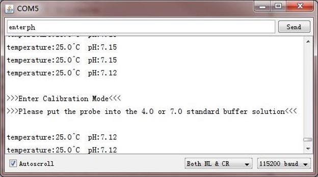
1.Upload the sample code to the Arduino board, then open the serial monitor, after you can see the temperature and pH. If you added a temperature sensor, be sure to write the corresponding function and call it.
2.Wash the probe with distilled water, then absorb the residual water-drops with paper. Insert the pH probe into the standard buffer solution of 7.0, stir gently, until the values are stable.
3.After the values are stable, the first point can be calibrated.
4.Input enterph command in the serial monitor to enter the calibration mode.
Step 4: Calibrate Per Detailed Instructions From DFRobot Pt 2
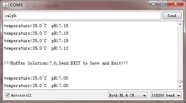
Input calph commands in the serial monitor to start the calibration. The program will automatically identify which of the two standard buffer solutions is present: either 4.0 or 7.0. In this step, the standard buffer solution of 7.0 will be identified.
Step 5: Calibrate Per Detailed Instructions From DFRobot Pt 3
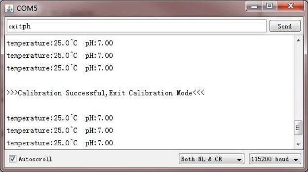
After the calibration, input exitph command in the serial monitor to save the relevant parameters and exit the calibration mode. Note: Only after inputing exitph command in the serial monitor can the relevant parameters be saved.
After the above steps, the first point calibration is completed. The second point calibration will be performed below.
1.Wash the probe with distilled water, then absorb the residual water-drops with paper. Insert the pH probe into the standard buffer solution of 4.0, stir gently, until the values are stable.
2. After the values are stable, the second point can be calibrated. These steps are the same as the first calibration step. The specific steps are as follows:
3. Input enterph command in the serial monitor to enter the calibration mode.
4. Input calph commands in the serial monitor to start the calibration. The program will automatically identify which of the two standard buffer solutions is present: either 4.0 and 7.0 In this step, the standard buffer solution of 4.0 will be identified.
5. After the calibration, input the exitph command in the serial monitor to save the relevant parameters and exit the calibration mode. Note: Only after inputing exitph command in the serial monitor can the relevant parameters be saved.
After the above steps, the second point calibration is completed.
After completing the above steps, the two-point calibration is completed, and then the sensor can be used for actual measurement. The relevant parameters in the calibration process have been saved to the EEPROM of the main control board.
Step 6: Assemble Hardware
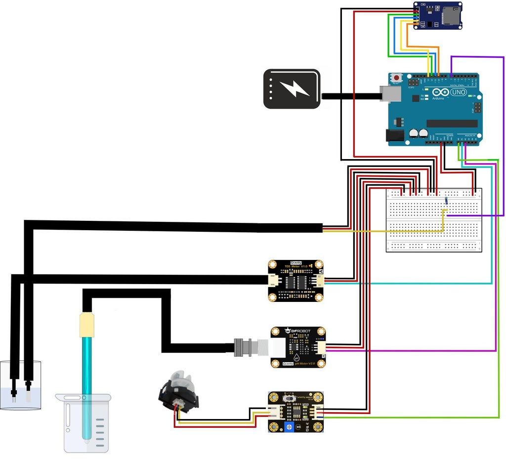
To begin, plug in all wires and sensors as detailed in the diagram. For a higher quality diagram, download and open the svg file attached to this step.
Important notes:
· Make sure the cables are plugged in the correct way as shown in the diagram for the turbidity sensor (if they aren’t plugged in right the sensor won’t work)!
· The Resistor is a 5k ohm resistor
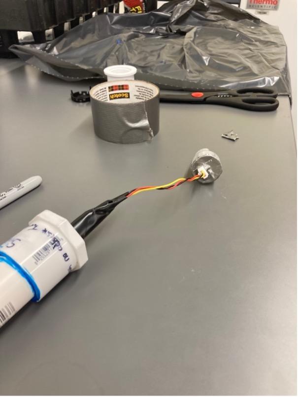
Step 7: Waterproofing the Turbidity Sensor Pt. 1
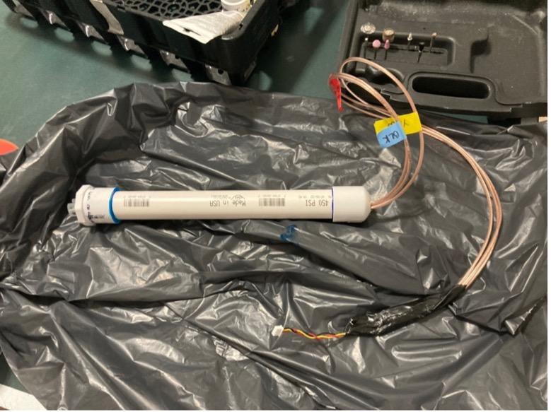
Next, we need to waterproof the turbidity sensor. Unfortunately, the only Arduino compatible turbidity sensor we could find is not submergible, so this process will fix that problem. Attached is a picture of the finished product.
Step 8: Waterproofing the Turbidity Sensor Pt. 2
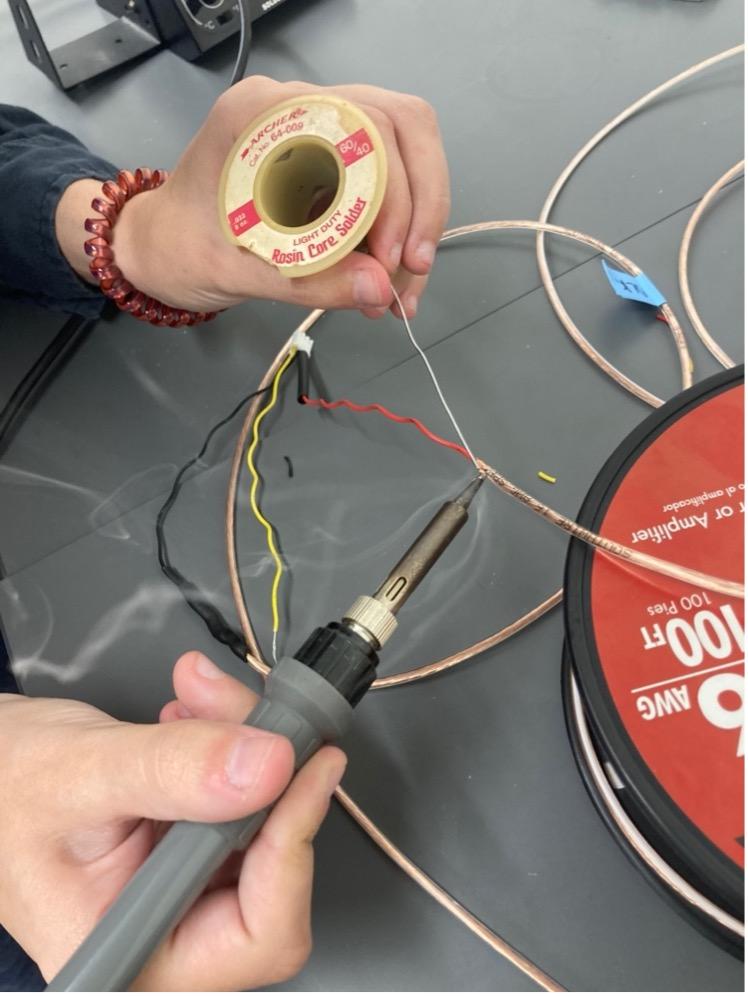
First, we need to lengthen the wires. We cut the wires for the turbidity sensor and soldered it to 3 ft of 16 AWG speaker wire.
Step 9: Waterproofing the Turbidity Sensor Pt. 3
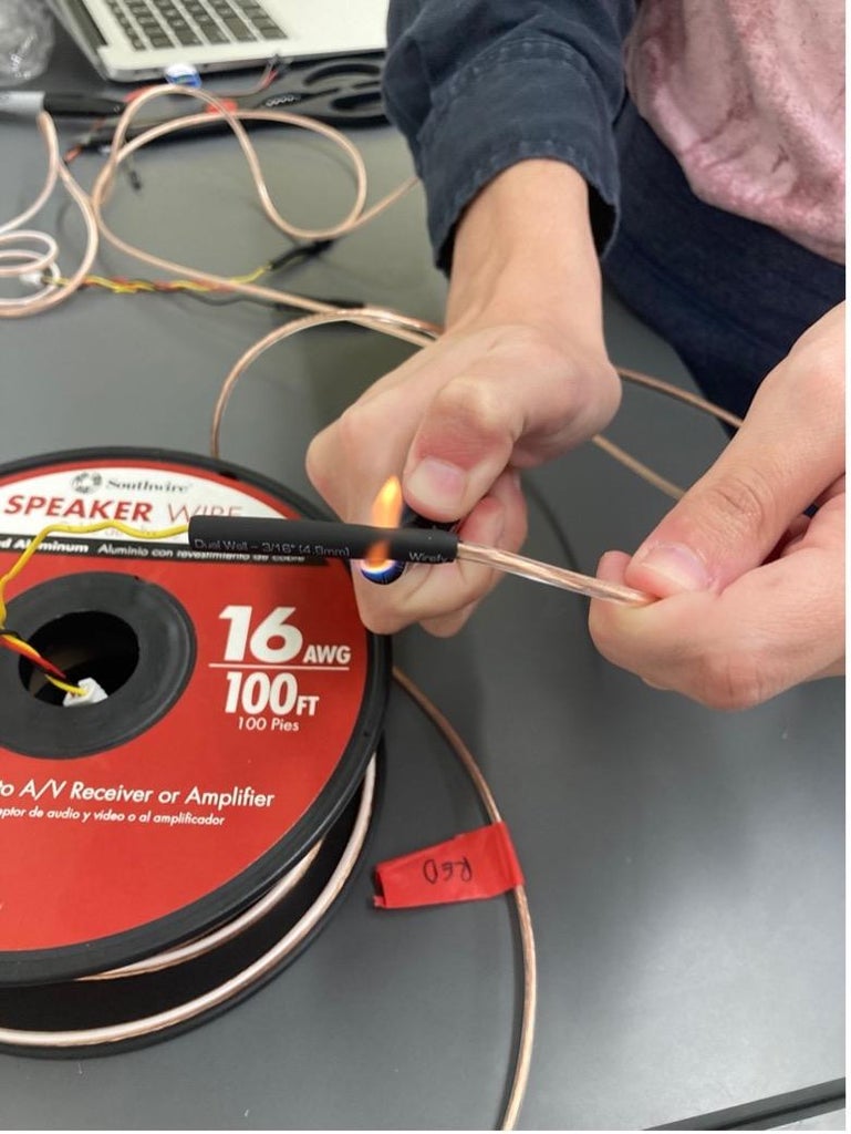
After that, we applied heat shrink tubing to protect the soldered connections.
Step 10: Waterproofing the Turbidity Sensor Pt. 4
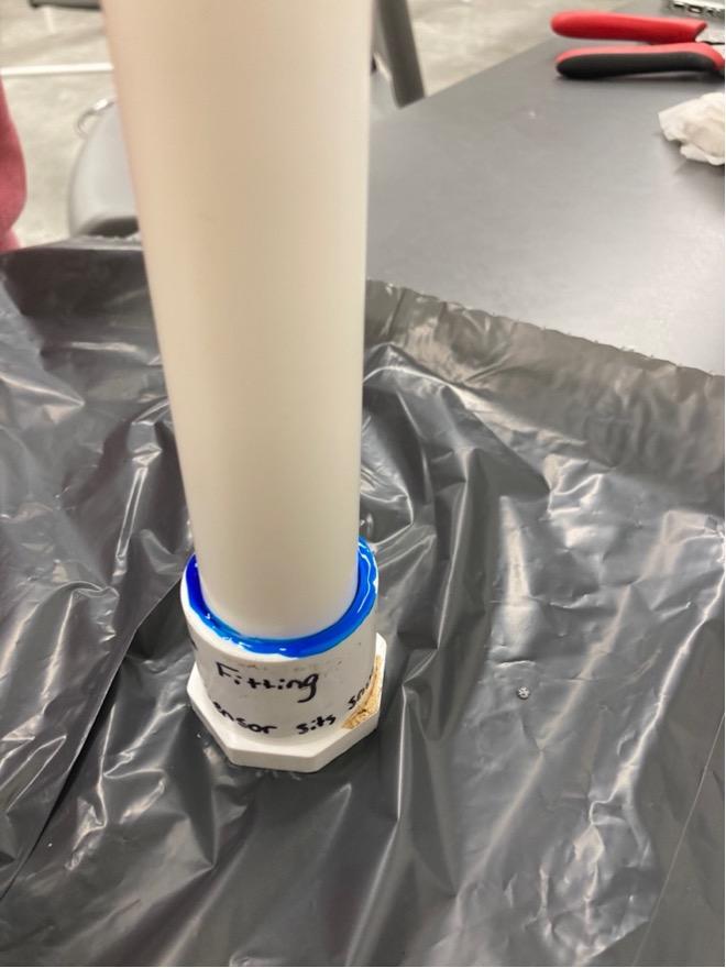
After that, take a 1 ft long 1†PVC pipe and connect it to a 1-1/4-in x 1-in PVC bushing using PVC Cement.
Step 11: Waterproofing the Turbidity Sensor Pt. 5
Remove the backing off the turbidity sensor and cover the back with duct tape and pass the turbidity wires through the bushing.
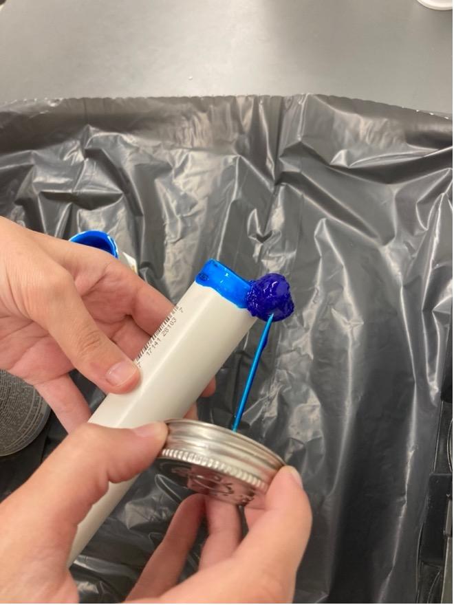
Step 12: Waterproofing the Turbidity Sensor Pt. 6
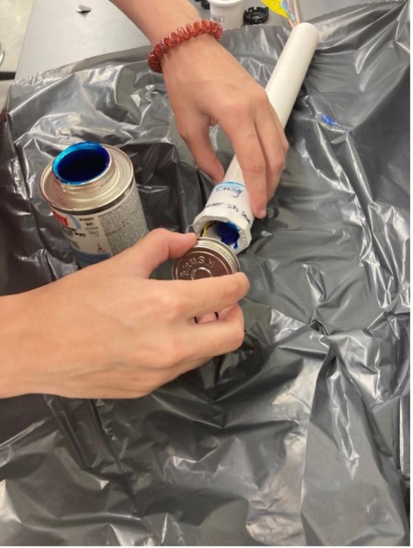
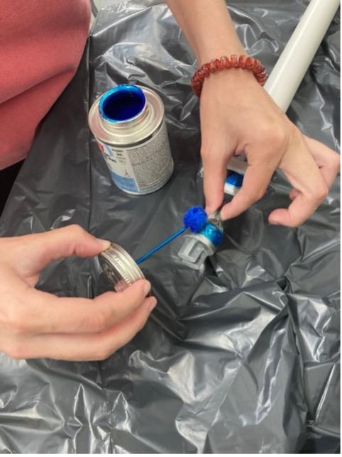
Then apply PVC Cement on both the turbidity sensor and bushing.
Step 13: Waterproofing the Turbidity Sensor Pt. 7
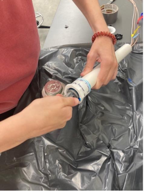
Finally take a 1†Sized cap and drill a hole in the top to fit the wires through. (If necessary, a Dremel can increase the size of the hole).
Step 14: Waterproofing the Turbidity Sensor Pt. 8
Then apply sealant in between the hole and the wires to waterproof it. Apply PVC Cement on the cap and attach it. The turbidity sensor is now waterproofed.
Step 15: Code Setup
To begin, copy and paste this code in to the Arduino IDE or download the attached file.
DFRobot Gravity: Analog TDS Sensor / Meter For Arduino

 <https://www.dfrobot.com/wiki/index.php/Gravity:_Analog_TDS_Sensor_/_Meter_For_Arduino_SKU:_SEN0244>

 Created 2017-8-22

 By Jason <[email protected]@dfrobot.com>

 GNU Lesser General Public License.

 See <http://www.gnu.org/licenses/> for details.

 All above must be included in any redistribution
/***********Notice and Trouble shooting***************
1. This code is tested on Arduino Uno and Leonardo with Arduino IDE 1.0.5 r2 and 1.8.2.
2. More details, please click this link: <https://www.dfrobot.com/wiki/index.php/Gravity:_Analog_TDS_Sensor_/_Meter_For_Arduino_SKU:_SEN0244>
// also used https://www.youtube.com/watch?v=5Dp-XatLySM

#include <OneWire.h>

#include <DallasTemperature.h>

#include <SD.h>

#include <SPI.h>

#include "DFRobot_PH.h" //added from PH Code

#include <EEPROM.h> //Added from PH Code

File myFile;

#define ONE_WIRE_BUS 7

#define TdsSensorPin A1 //verify plugged in here

#define PH_PIN A2 //

#define VREF 5.0    // analog reference voltage(Volt) of the ADC 0ther option is 3.3/5.0

#define SCOUNT 30          // sum of sample point

int analogBuffer[SCOUNT];   // store the analog value in the array, read from ADC

int analogBufferTemp[SCOUNT];

int analogBufferIndex = 0,copyIndex = 0;

int pinCS = 53; // Pin 10 on Arduino UNO

int sensorPin = A0; //added from turbidity

float averageVoltage = 0,tdsValue = 0,temperature = 25;

float voltage,phValue;

float Celcius=0;

float Fahrenheit=0;

float volt; //added from turbidity

float ntu; //added from turbidity

DFRobot_PH ph;

OneWire oneWire(ONE_WIRE_BUS);

DallasTemperature sensors(&oneWire);

void setup()

{

   Serial.begin(115200);

   ph.begin(); //added from ph

   sensors.begin();

   pinMode (pinCS, OUTPUT);

   pinMode(TdsSensorPin,INPUT);

   // SD Card Initialization

   if (SD.begin())

   {

     Serial.println("SD card is ready to use.");

   } else

   {

     Serial.println("SD card initialization failed");

     return;

   }

}

void loop()

{

 volt = 0; //beginning of added from turbidity

   for(int i=0; i<800; i++)

   {

       volt += ((float)analogRead(sensorPin)/1023)*5;

   }

   volt = volt/800;

   volt = round_to_dp(volt,1);

   if(volt < 2.8){

     ntu = 1540;

   }else{

     ntu = -576.12*square(volt)+3393.2*volt-3443.2;

    // ntu = -1120.4*square(volt)+5742.3*volt-4353.8;

   } //end of added from turbidity

  static unsigned long analogSampleTimepoint = millis();

  if(millis()-analogSampleTimepoint > 40U)    //every 40 milliseconds,read the analog value from the ADC

  {

    analogSampleTimepoint = millis();

    analogBuffer[analogBufferIndex] = analogRead(TdsSensorPin);   //read the analog value and store into the buffer

    analogBufferIndex++;

    if(analogBufferIndex == SCOUNT)

        analogBufferIndex = 0;

  }

 static unsigned long timepoint = millis();      //added from ph

   if(millis()-timepoint>1000U){                 //time interval added from ph

       timepoint = millis();          //added from ph

       voltage = analogRead(PH_PIN)/1024.0*5000; // read the voltage

       phValue = ph.readPH(voltage,temperature);  //added from ph

   }

  static unsigned long printTimepoint = millis();

  if(millis()-printTimepoint > 800U)

  {

     printTimepoint = millis();

     for(copyIndex=0;copyIndex<SCOUNT;copyIndex++)

       analogBufferTemp[copyIndex]= analogBuffer[copyIndex];

    averageVoltage = getMedianNum(analogBufferTemp,SCOUNT) * (float)VREF / 1024.0; // read the analog value more stable by the median filtering algorithm, and convert to voltage value

     float compensationCoefficient=1.0+0.02*(temperature-25.0);   //temperature compensation formula: fFinalResult(25^C) = fFinalResult(current)/(1.0+0.02*(fTP-25.0));

     float compensationVolatge=averageVoltage/compensationCoefficient; //temperature compensation

     tdsValue=(133.42*compensationVolatge*compensationVolatge*compensationVolatge - 255.86*compensationVolatge*compensationVolatge + 857.39*compensationVolatge)*0.5; //convert voltage value to tds value

    // Serial.print("voltage:");

    // Serial.print(averageVoltage,2);

     //Serial.print("V  ");

     sensors.requestTemperatures();

     Celcius=sensors.getTempCByIndex(0);

     Fahrenheit=sensors.toFahrenheit(Celcius);

     //Serial.print(compensationCoefficient);

     //Serial.print("compensationCoefficient");

     //Serial.print(temperature);

     //Serial.print("temperature");

     Serial.print(millis());

     Serial.print("time since start in milliseconds");

     Serial.print(" C ");

     Serial.print(Celcius);

     Serial.print(" F ");

     Serial.println(Fahrenheit);

     Serial.print(volt );

     Serial.print(" V ");

     Serial.print(ntu );

     Serial.print(" NTU ");

     Serial.print("pH:");

     Serial.print(phValue);

     Serial.print(" TDS Value:");

     Serial.print(tdsValue,0);

     Serial.println("ppm");

  }

    ph.calibration(voltage,temperature);          // calibration process by Serail CMD

 {

 myFile = SD.open("test.txt", FILE_WRITE);

 if (myFile){

   myFile.print(millis());

   myFile.print(",");

   myFile.print(Celcius);

   myFile.print(",");

   myFile.print(Fahrenheit);

   myFile.print(",");

   myFile.print(phValue);

   myFile.print(",");

   myFile.print(volt);

   myFile.print(",");

   myFile.print(ntu);

   myFile.print(",");

   myFile.println(tdsValue,0);

   //myFile.print(",");

   myFile.close(); // close the file

 }

 //if the file didn't open, print an error:

 else {

   Serial.println("error opening test.txt");

 }

  } delay (300000); // use 500 for short term troubleshooting/lab testing,300000 for field testing, 300,000 milliseconds=5 minutes, 500 milliseconds=0.5 second

}

float round_to_dp( float in_value, int decimal_place ) //begin

{

 float multiplier = powf( 10.0f, decimal_place );

 in_value = roundf( in_value * multiplier ) / multiplier;

 return in_value;

}

int getMedianNum(int bArray[], int iFilterLen)

{

    int bTab[iFilterLen];

    for (byte i = 0; i<iFilterLen; i++)

     bTab[i] = bArray[i];

     int i, j, bTemp;

     for (j = 0; j < iFilterLen - 1; j++)

     {

     for (i = 0; i < iFilterLen - j - 1; i++)

        {

       if (bTab[i] > bTab[i + 1])

          {

       bTemp = bTab[i];

          bTab[i] = bTab[i + 1];

       bTab[i + 1] = bTemp;

        }

    }

     }

     if ((iFilterLen & 1) > 0)

   bTemp = bTab[(iFilterLen - 1) / 2];

     else

   bTemp = (bTab[iFilterLen / 2] + bTab[iFilterLen / 2 - 1]) / 2;

     return bTemp;

} Step 16: Field Deployment Pt. 1
Now that all hardware is functioning, it is time to finish the assembly and deploy it to the field. Drill two holes to fit the wires through in the side of the box and then apply flex tape around the holes to block water. Sealant can also be used in this case depending on how exposed the system will be to water.
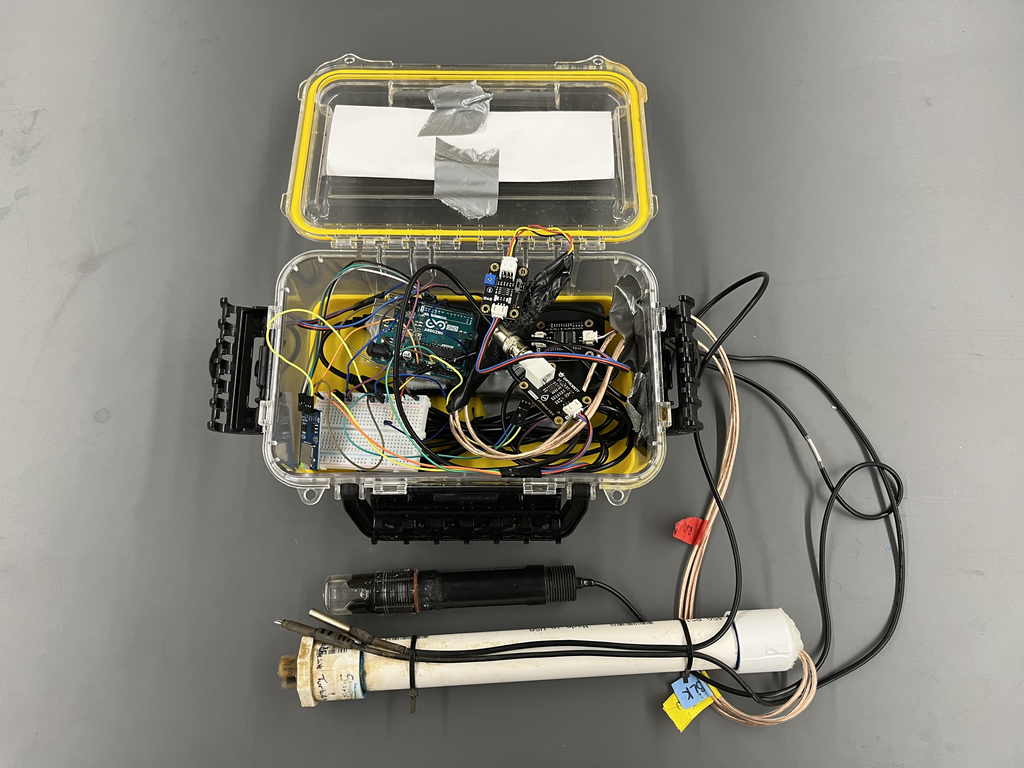
Step 17: Field Deployment Pt. 2
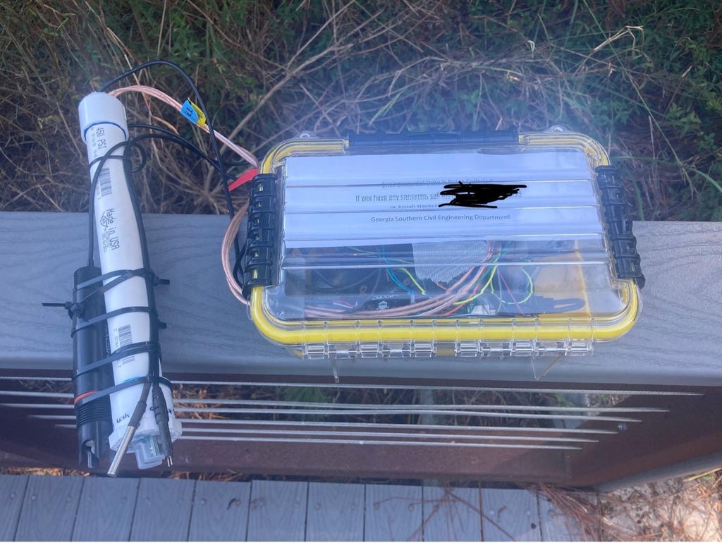
After putting all necessary hardware in the box, the system should look something like this
Step 18: Field Deployment Pt. 3
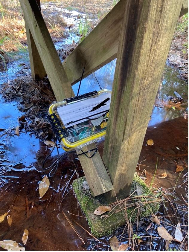
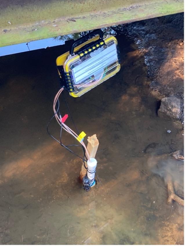
Depending on the location, there are different options for deployment. For one deployment, we found a bridge with conduit running underneath that we zip tied the box to. For the other deployment we zip tied it to the support of a bridge. Additionally, for the second deployment, we zip tied the sensor probe to a stake we drove into the creek bed for additional stability. With a 20,000 Mah battery, we consistently got 6 days of battery life at a time.
Right before you deploy, reformat the sd card, and ensure that the delay function in the code is set to an appropriate time depending on where you are deploying. (We use 300,000 milliseconds for field testing and 500 milliseconds for lab testing). Then, insert the sd card into the sd card adapter and plug the arduino into a fully charged battery. Now, the arduino will start taking measurements at the specified frequency and the sensors are ready to be inserted in the water.
Step 19: Retrieving Data Pt. 1
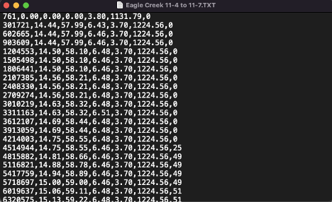
Once you retrieve the SD card from the Arduino, it is a relatively easy process to convert that data to an excel spreadsheet. The Arduino is programed to store the data it retrieves in a plaintext file with each variable separated by a comma and each reading on a new line:
The variables are
Step 20: Retrieving Data Pt. 2
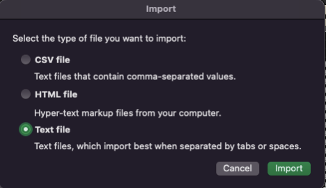
Open a new excel sheet and go to File>Import then click on text file
Step 21: Retrieving Data Pt. 3
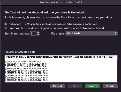
Make sure that delimited is selected, then click next.
Step 22: Retrieving Data Pt. 4
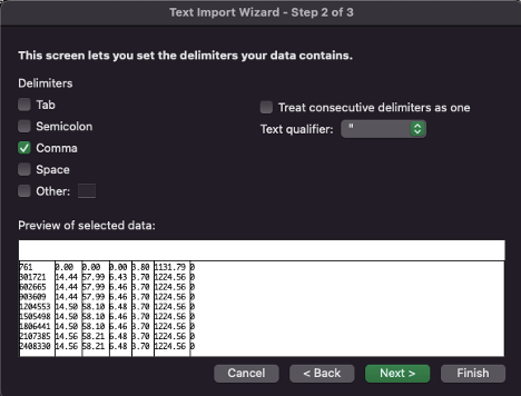
Make sure that comma is the only delimiter selected, then click next
Step 23: Retrieving Data Pt. 5
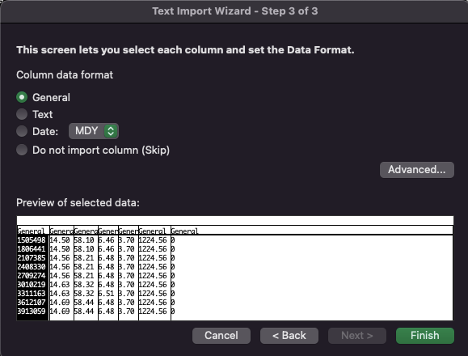
Make sure that the “General†format is selected for all columns, then click finish.
Step 24: Retrieving Data Pt. 6
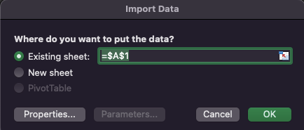
Select where you want the data to be imported to and click OK. After this we recommend formatting/plotting your data depending on what the intended application of your research is.
Step 25: Troubleshooting Pt. 1
With any project like this, you are likely to run into some technical difficulties. The following pointers should allow you to troubleshoot some common errors we encountered during the development process.
-Regardless of the issue, restart both the Arduino and your computer before you worry about the problem.
-If you are getting weird values, make sure that everything is plugged in completely!
-If all else fails and you are getting an error message or encountering a problem you have never seen before, it never hurts to google the error message or symptoms.
Step 26: Troubleshooting Pt. 2
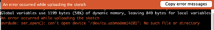
Sometimes when you run the Arduino, you get this error:
Step 27: Troubleshooting Pt. 3
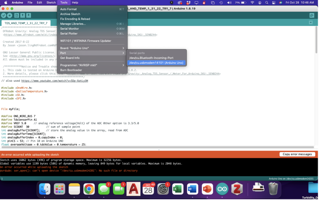
If you get this error, go to Tools -> Port and select the usbmodem port. This error happens if the computer doesn’t automatically detect the Arduino when it’s plugged in. Selecting the port the Arduino is plugged into fixes this issue.
This article was first published on Instructables.
Cr: https://www.instructables.com/Arduino-Water-Quality-Monitoring-System/
Author: RowlesGroupResearch


