
The Pet Pot
Plants are complicated. Even though plants can be comforting companions, they have specific needs that can confuse inexperienced gardeners. For these struggling gardeners, I introduce the Pet Pot.
The Pet Pot is a pot that helps you monitor your plants. It measures specific aspects of the environment and displays the data on a screen along with an emoji to represent how the plant is feeling. By providing the environment's soil moisture percentage, air quality, and temperature, new plant owners will have an easier time determining the "happiness" of their green friend.
I would like to thank Ms.Berbawy for providing the opportunity to work on a project like this. Furthermore, I would like to thank Berbawy Makers for providing the many tools and materials I used in this project. Lastly, I would like to thank Mukesh Sankhla for creating an amazing project that inspired this one.
I am Erik Shen, an Irvington High school student taking Ms.Berbawy's Principles of Engineering (PLTW) course, and I created this project for the SIDE project assignment of the engineering course.

Supplies
Tools/Machines:
- PRUSA i3 MK3S+ (3D Printer)- Soldering kit- Dial Calipers
Applications:
- Fusion 360 (CAD software)- PRUSA Slicer- Visual Studio Code- Mind+ programming softwareStep 1: Measure Pot Dimensions

First, I measured the dimensions of the pot that I planned to use. For this step, I measured the radius of the top, the radius of the bottom, and the height of the pot. The parts of the pot I measured can be seen in the diagram provided above. I utilized dial calipers to collect the measurements and recorded them in the engineering notebook I dedicated to this project.
My pot's top radius, bottom radius, and height were 105mm, 73mm, and 92mm respectively. I used these measurements to design the hole that the pot will be placed in.
Step 2: Design the Pot

After I determined the measurements of the pot, I designed the two parts of the pot (the top and the bottom). I used Fusion360 to design the CAD models for my pot.
The Top Part:
The purpose of the top part is to hold the plant that I used for my project. There are two holes in this part: one on the bottom and one on the top. I used the radius measurements from step 1 to construct the size of the holes and the height of my pot for the distance between the two holes. To create the cavity that the plant rests in, I lofted the two holes to cut into a rectangular prism. The bottom hole also acts as a way for excess water to seep through the soil and out the bottom of the pot. Lastly, I added a join extrusion on the bottom of the part to make the connection between the top and bottom parts easy and convenient.
The Bottom Part:
The purpose of the bottom part is to hold all the electronics for this project. On the front, there is a slot for my minicomputer to slip in. The measured dimensions of the minicomputer screen are 70.00mm by 51.00mm and I added a tolerance of 0.254mm for the screen. There's also a hole at the center of the base for the water to flow from the top of the pot out the bottom. This hole also acts as a structure for me to wrap my wires around. In addition, I've added a hole on the right side of my design to accommodate the wires that will be coming in and out of the pot (USB C and Soil Moisture Sensor). Lastly, there's a cut extrusion on the top of the part to complement the top part. This cut complements the extrusion of the top part which allowed me to connect the two pieces of my pot easily.
Throughout the designing process, I performed test prints to ensure my tolerances and measurements would work well. I printed the top part on its top to prevent overhang and the bottom part on its base.
I have provided the CAD files and a preview of the 3D models below.
Step 3: Waterproof the Soil Moisture Sensor

Since, I wanted to be able to water my plant while it sits in the pot, I had to waterproof the top portion of my soil moisture sensor. I measured the dimensions of the soil moisture sensor with a dial caliper and recorded the measurements into my engineering notebook.
 Case Top:
The top half of the case was designed to protect the sensor's electronic while still allowing a connection to be made with the analog port. To accomplish this, I designed a 31.43mm by 34.00mm by 5.6mm rectangle that I molded to match the soil moisture sensor. The port was 10.2mm by 6.9mm by 3.00mm which was replicated onto my design with a tolerance of 0.2mm. I chose a tolerance of 0.2 because I wanted the sensor to fit tightly onto the case. I also added 2 holes on the sides of the case which will help me align the two pieces.
Case Bottom:
The bottom half of the case was designed to complement the top half. It is also 31.43mm by 34.00mm by 5.6mm and has identical fillets and extrusions to the top half. Most notably, the bottom half has 2 pegs that fit into the holes of the case's top half. Since I placed the holes and pegs on the case to mirror each other, I was able to connect the two pieces of the case like Legos once I printed them out.
Once I finished the design, I 3D printed the two pieces out, encased my sensor with the case, and used tape to ensure the case could not fall apart.
I have provided the CAD file and a preview of the 3D model below.
Step 4: Prepare the Circuit
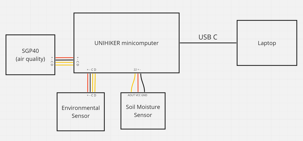
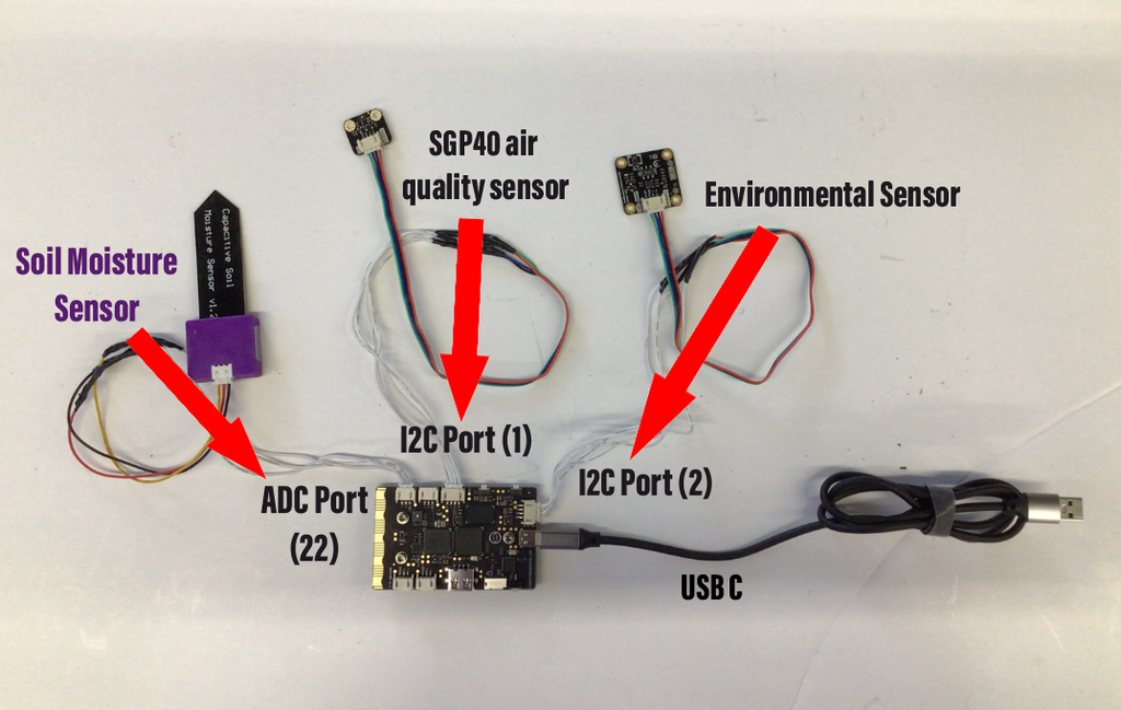
Once I finished all my 3D printing and designing, I worked on the circuit. I've provided a cartoon circuit diagram above to illustrate the connections I made for my project. I stripped the wires connecting the sensors and minicomputer and intertwined them together. After I connected the wires together, I soldered the two connecting wires together. To secure the connection, I wrapped the exposed wires with electrical tape.
The two digital sensors (environmental and air quality) are connected to the I2C ports on the minicomputer. The soil moisture sensor on the other hand is connected to the analog-to-digital convertor port labelled 22 that is found next to the buttons on the minicomputer. The location of the port is important because I needed to reference it in my code. Then I used the minicomputer's USB C port to connect a wire to my laptop's USB port. This connection allowed me to upload my Python code to the minicomputer. I used a USB C adapter to turn the wire 90 degrees to allow me to fit everything better in the bottom part of the pot. After I connected everything together, I began setting up the code for my sensors.
Step 5: Coding the Project
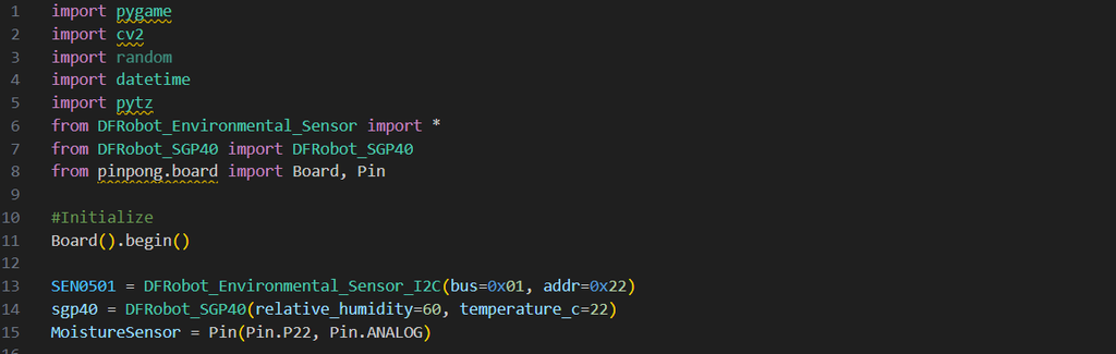
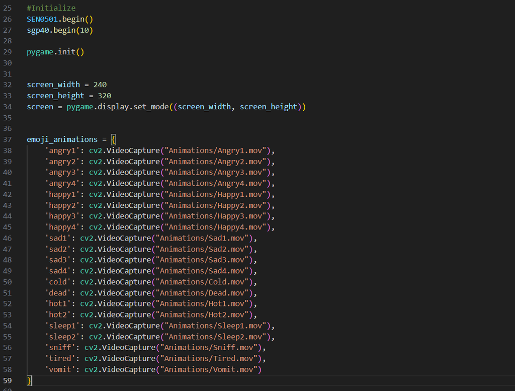

When coding, I referred to documentation and examples of the modules that I implemented in my final code. I utilized pygame (for display), cv2 (for the images and gifs), random (to generate random intervals), datetime (to set measurement intervals), pytz (to set time zone), pinpong (to interact with the minicomputer), DFRobot_EnvironmentalSensor (for the environmental sensor), and DFRobot_SGP40 (for the air quality sensor). I created the program in Visual Studio Code and then uploaded it onto my minicomputer. I've provided what the emoji, data, and icons will look like in some of the examples below. The extended folder of animations, icons, and emojis can be found in this google drive folder: Folder.
Code Explanation
1. At the beginning of the program, I imported the modules I used and defined some variables that I planned to refer to later in my code.
2. I initialized my sensors and the pygame graphics. I also used OpenCV to manage the animations that I planned to display on the screen. The images and animations I utilized for my project were provided by the original creator of the Pet Pot.
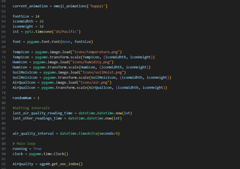
3. I set the default animation of my pot to be a happy face as a placeholder for the later segments of the code. I also set the time with pytz to record the amount of time that has passed. Below that, I set the size of the fonts and icons that will be displayed. Then, I labeled and loaded the images I planned to use. Lastly, I set time intervals here that would determine how often the sensors would collect and communicate the data measurements. I set the intervals of my program to 5 seconds.
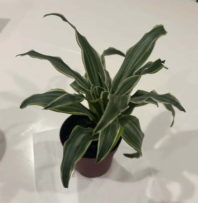
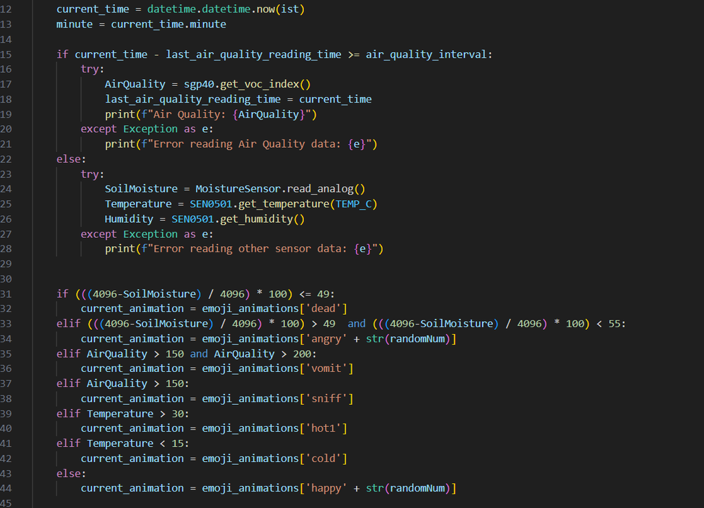
4. I created a loop that updates the time and tells the sensors to record data based on the current time and the intervals I set. In the if statements, I utilized a try-except operation to determine if any of the sensors were either broken or not connected properly. Then I created a series of if and elif statements that would help determine the animation icon that should be displayed depending on the recorded values. Here I configured the optimal temperature, air quality, and soil moisture of my plant: a Dracaena.
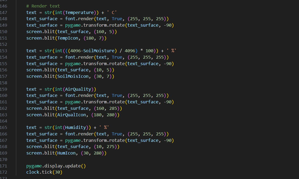
5. Finally, I rendered the text and icons on the screen with pygame. I assigned coordinates to each icon to make each one take up one corner of the screen.
Step 6: Import Code
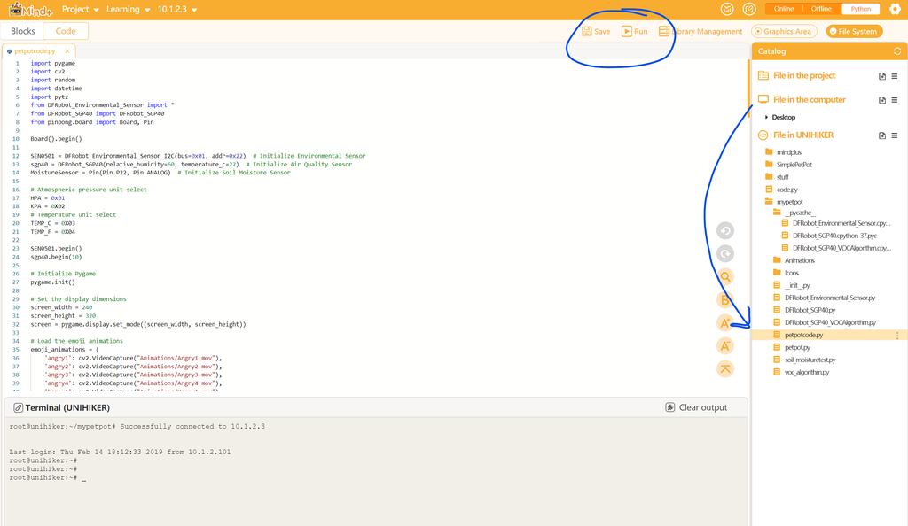
After I finished creating the program, I set up the Mind+ to upload the code onto my minicomputer. This process was very tedious but I followed a tutorial with steps similar to the images I've provided above:
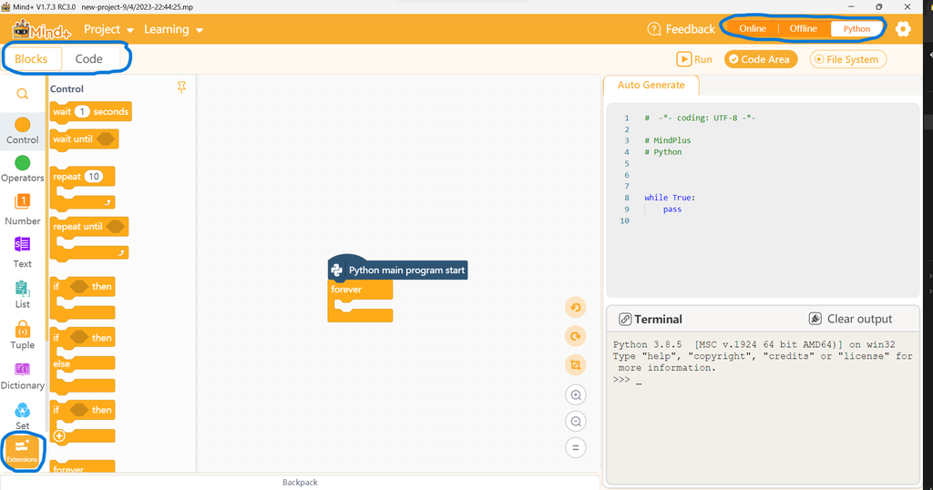
1. I set the program to "Python", selected "Blocks", and opened the "Extensions" tab
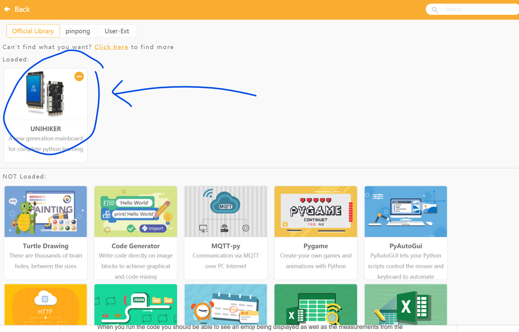
2. I selected the UNIHIKER extension which is the same brand as the minicomputer I used
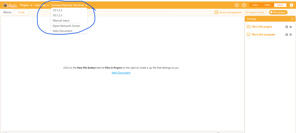
3. I selected "Connect Remote Terminal" and because my minicomputer was plugged in through USB C, I selected its address which is 10.1.2.3
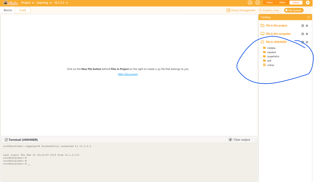
4. I moved my files from "File in Computer" to "File in UNIHIKER"
5. I clicked "Run" to start my code and waited for the minicomputer's screen to respond
Here are the program files for reference: Files
Step 7: Pot Assembly


Here are my steps to assembly:
1. I prepared my electronics within the bottom part of the pot. I placed the minicomputer into the slot and wrapped the wires around the hole on the base. I fed the USB C wire and the soil moisture sensor wire through the hole I've made.
2. I connected my minicomputer to my laptop to import the code via the Mind+ program.
3. I assembled the two pot pieces together via the extrusions I created during my design process.
4. I placed my Dracaena plant with its pot into the hole of the pot
5. I planted the soil moisture sensor into the soil
There you go, the pet pot is finished. I've provided some pictures and a demonstration video below to show off my project.
Step 8: Final Product

This article was first published on Instructables
Cr: https://www.instructables.com/The-Pet-Pot/
Author: erikshen123


