
In the age of smart homes and automated gadgets, why should your backyard farm be any different? If you’re passionate about raising chickens but want to streamline your daily chores and ensure your flock’s safety with minimal effort, building a DIY Smart Coop is the perfect project for you. By integrating modern technology into your chicken-keeping routine, you can create a coop that is not only efficient but also gives you peace of mind, knowing that your chickens are well-cared for, even when you’re not around.
The Vision Behind DIY Smart Coop
Raising backyard chickens has always been a rewarding experience, providing fresh eggs, natural pest control, and a closer connection to sustainable living. However, managing a chicken coop comes with its own set of challenges—early morning wake-ups to let the chickens out, late-night checks to ensure they’re safely tucked in, and constant vigilance to protect them from predators.
A smart coop solves these issues by automating key aspects of chicken care, combining the latest in agricultural technology with the charm of traditional backyard farming. Imagine being able to open and close your coop door from your phone, receiving real-time alerts if a predator is detected, or even checking on your chickens from anywhere in the world via live camera feeds. With a DIY Smart Coop, all of this is possible.
The DIY Smart Coop is designed to make this process easier and more efficient. By automating routine tasks, enhancing security, and providing remote monitoring capabilities, a smart coop allows you to focus on the joys of homesteading without being bogged down by the daily grind. It’s a perfect blend of tradition and technology, ensuring that your chickens are cared for with minimal effort, while you reap the rewards of fresh, farm-raised eggs and poultry for your table.
Why Build The DIY Smart Coop?
Taking on a DIY project like this not only allows you to customize your coop to your specific needs but also gives you the satisfaction of creating a high-tech, self-sufficient system. By building your own smart coop, you’ll be able to:
Reduce Your Workload: Automate routine tasks like opening and closing the coop door, feeding, and watering, so you can focus on enjoying your chickens rather than managing them.Enhance Chicken Safety: Implement predator-proof features and remote monitoring capabilities to ensure your chickens are safe, even when you’re not home.Stay Connected: Use WiFi cameras and smart sensors to keep an eye on your flock from anywhere, ensuring you’re always in the loop about their well-being.Customize to Your Needs: Tailor the design and features of your smart coop to suit your specific requirements, whether you have a large flock or just a few birds.Step 1: Demo Video
See the Smart Coop in Action!
Step 2: General Design

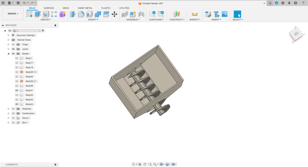
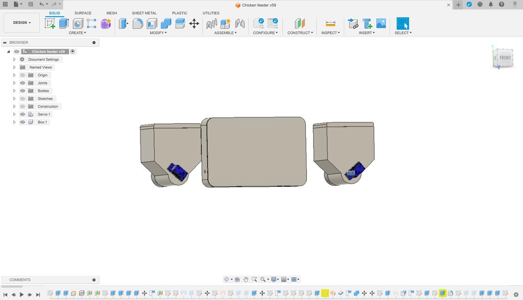
We began the design process by visualizing our concept in Fusion 360, where we meticulously adjusted dimensions, taper angles, and component layouts. Through iterative adjustments, we explored various configurations for the door and feeder mechanisms, optimizing both functionality and aesthetics. By testing different setups and refining our design based on simulation results, we ultimately settled on a design that balanced practical performance with visual appeal, ensuring that the final smart coop design was both efficient and attractive.
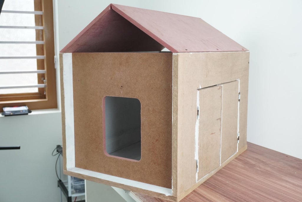
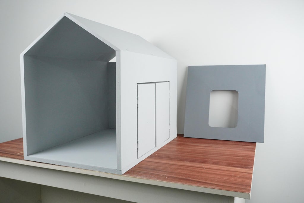
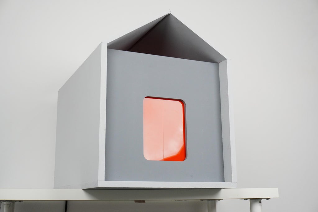
Step 3: Housing
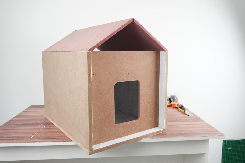
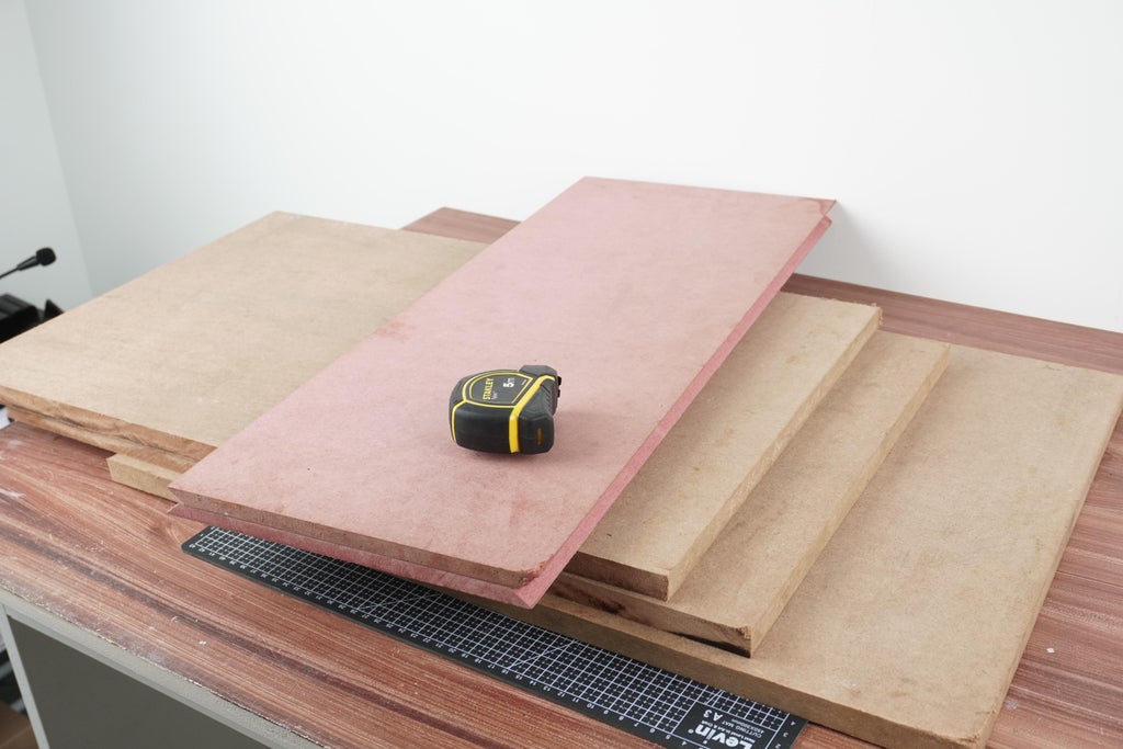
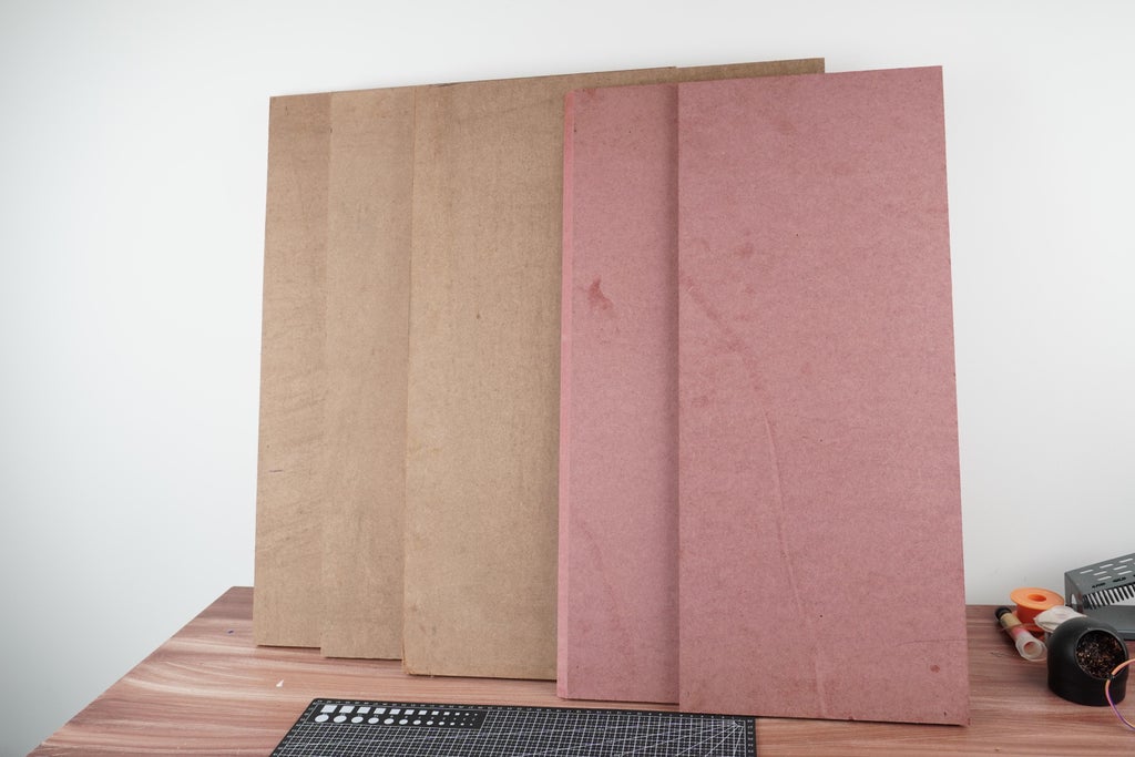
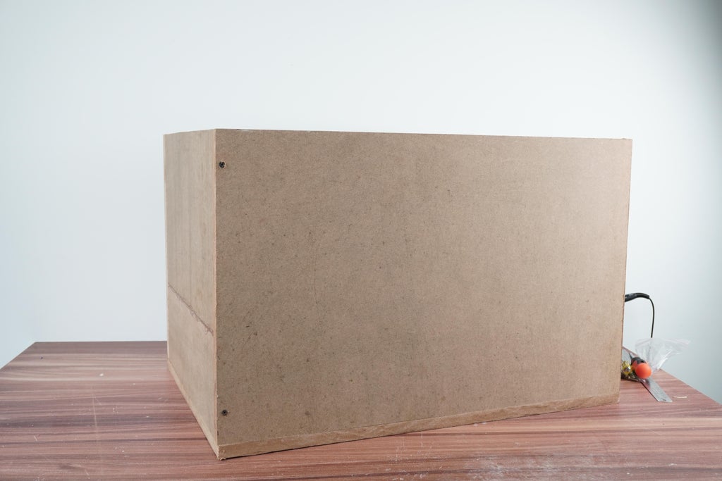
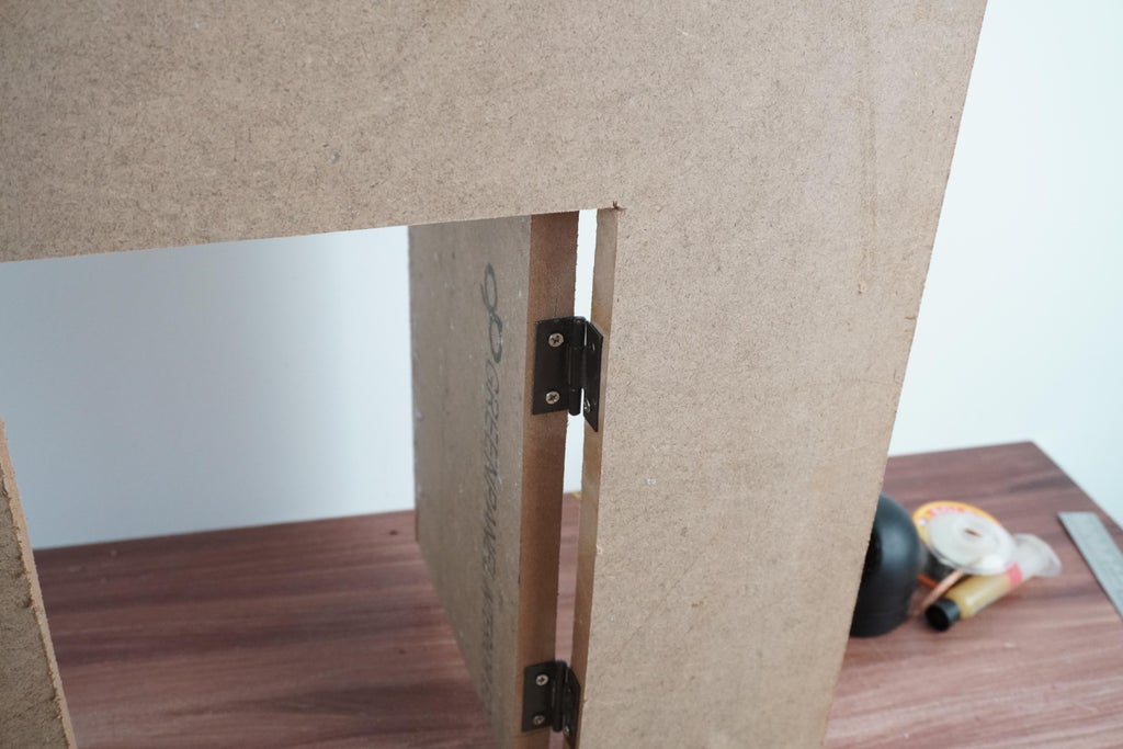
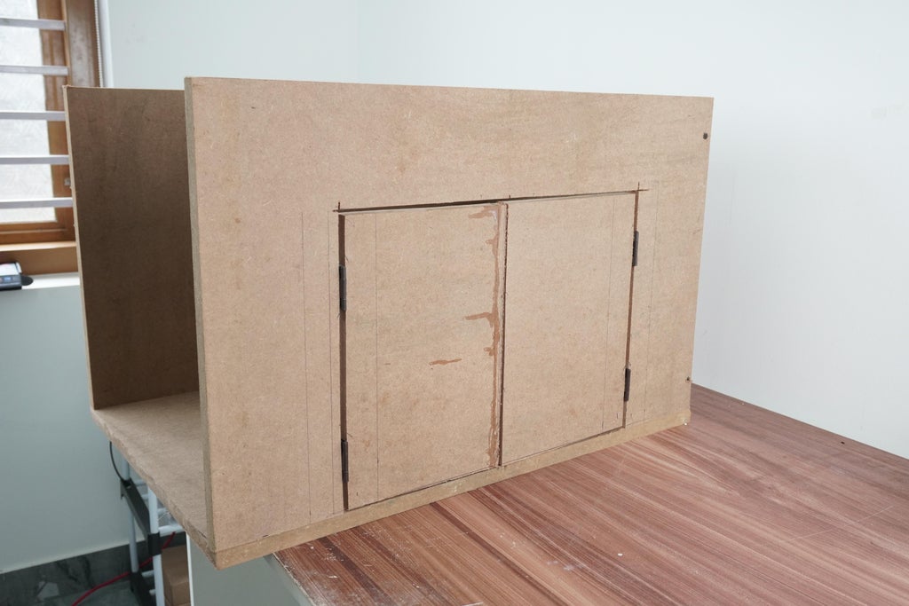
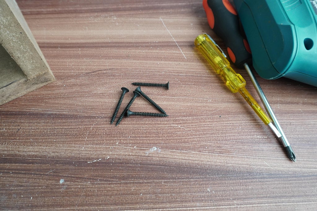
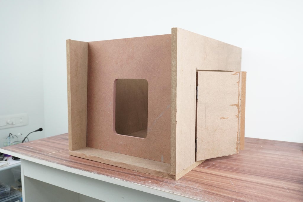
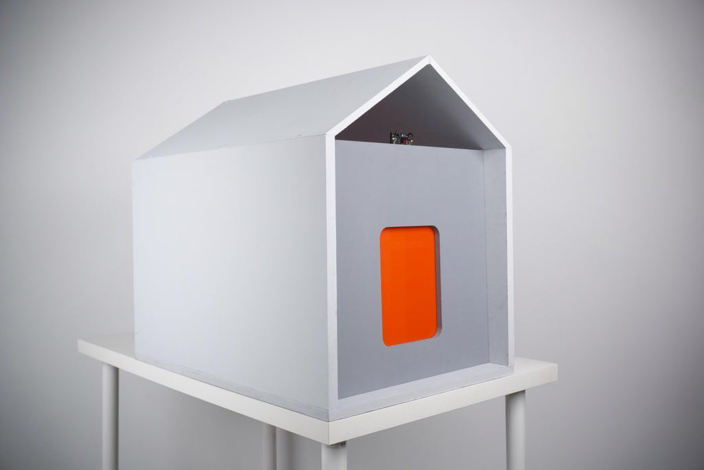
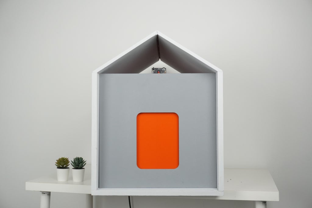
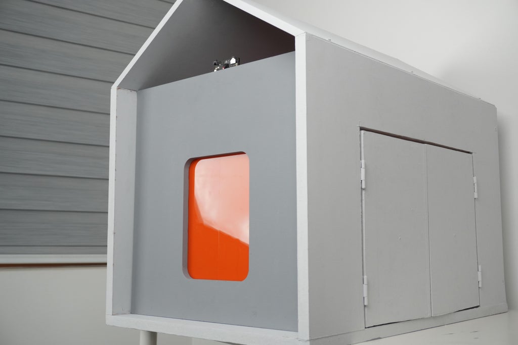
We constructed the housing using 3/4 inch MDF wood for the main structure, ensuring a strong and stable build. To achieve a precise fit, we used 1/2 inch MDF for the top section, which we tapered to give the project a retro aesthetic. The side panels were securely attached to the base with one-inch screws, while the door was fitted using 1/4 inch screws for the hinges. Before attaching the top portion, we primed the inner surface to streamline the finishing process, focusing on the outer surfaces for the final touch. The result is a durable, visually appealing housing that balances form and function.
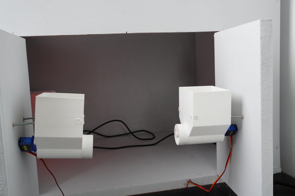
Step 4: Front Door Mechanism Setup
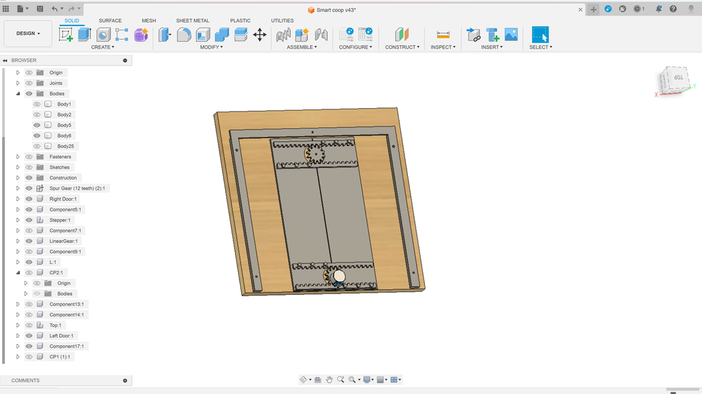
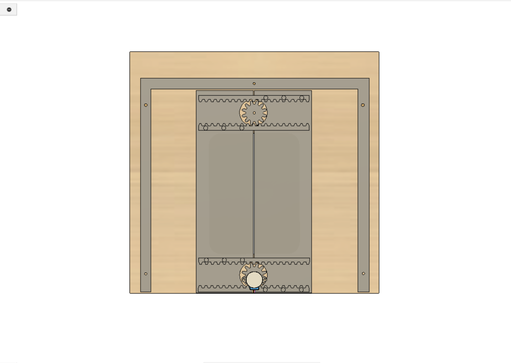
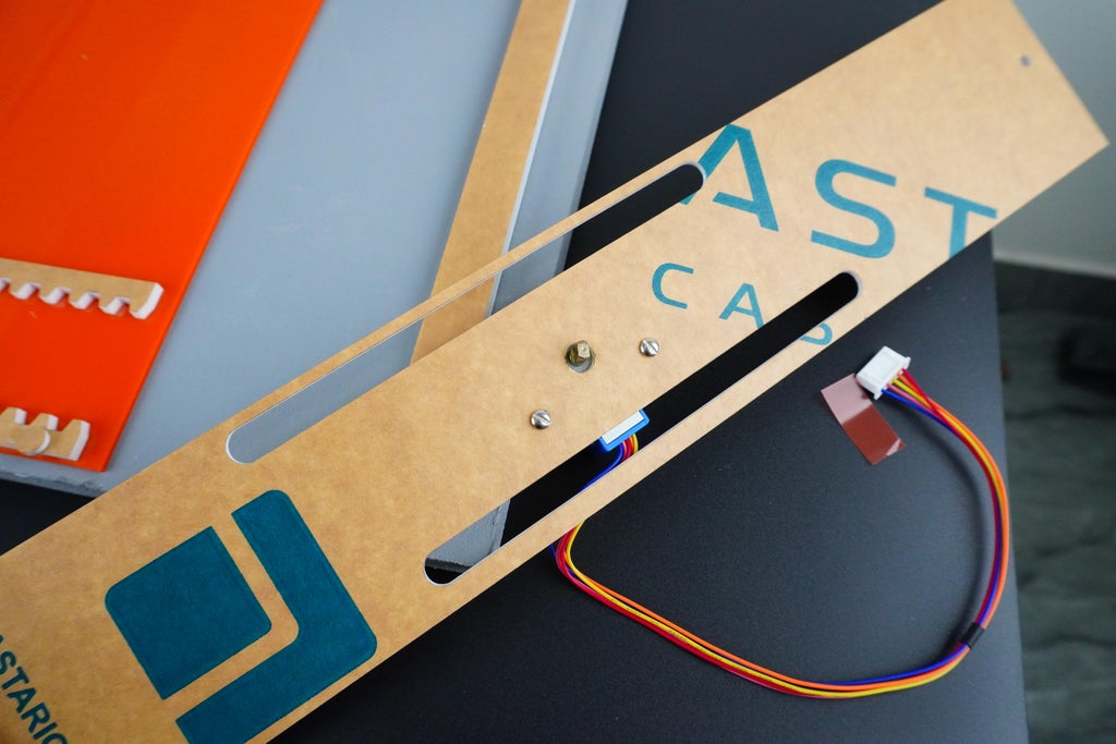
The front door of our smart coop is designed with both functionality and automation in mind, featuring a double sliding door mechanism that ensures secure and efficient operation. This design integrates precision engineering with modern materials, providing a reliable solution for automated chicken coop access.
Mechanism Overview
The double sliding door mechanism operates through a coordinated movement of two doors that slide horizontally in opposite directions to open and close the entrance of the coop. The entire setup is powered by a single stepper motor, ensuring synchronized movement and consistent performance.
Key Components and Materials
1.Circular Gears:
- Design: Two circular gears are used in the mechanism to translate the rotational motion of the stepper motor into linear motion, which drives the sliding doors.
- Material: These gears are precision-cut from 4mm acrylic sheets, ensuring durability and smooth operation.
- Positioning: Each circular gear is strategically placed at the top corners of the sliding door assembly, meshing with corresponding linear gears.
2.Linear Gears (Rack Gears):
- Design: The linear gears, also known as rack gears, interact with the circular gears to move the doors horizontally.
- Material: These gears are also cut from 4mm acrylic sheets, providing a sturdy track for the circular gears to engage.
- Function: As the stepper motor rotates the circular gears, the linear gears guide the doors along their sliding paths, ensuring precise and controlled movement.
3.Stepper Motor:
- Role: A single stepper motor drives the entire door mechanism, offering precise control over the opening and closing process.
- Integration: The motor is connected to the circular gears via a central drive shaft, which ensures that both gears rotate in unison, moving the doors simultaneously.
4.Acrylic Sheets:
- 4mm Acrylic Sheets:
- Used for constructing the circular gears, linear gears, and supporting structure.
- Offers a balance of strength and flexibility, allowing the gears to mesh smoothly while maintaining the overall integrity of the mechanism.
- 2mm Acrylic Sheets:
- Used for the door panels themselves, providing a lightweight yet durable solution for the closing plates.
- The thinner material reduces the overall weight of the doors, minimizing the load on the motor and gears while ensuring that the doors are robust enough to withstand regular use.
Construction Process
1.Designing the Components:
- DXF Files: All components were designed using CAD software, with DXF (Drawing Exchange Format) files generated for laser cutting. This ensures that each part is accurately dimensioned and precisely cut.
- Gear Design: The circular and linear gears were meticulously designed to mesh perfectly, allowing for smooth operation without slippage or misalignment.
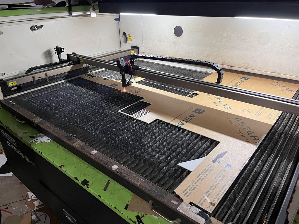
2.Laser Cutting:
- The DXF files were sent to a laser cutter to create the individual components from the acrylic sheets. Laser cutting ensures clean edges and precise tolerances, which are crucial for the seamless operation of the gear-driven mechanism.
- Acrylic Cutting: The 4mm sheets were used to cut the gears and structural components, while the 2mm sheets were used for the door panels.
3.Assembly:
- Mounting the Gears: The circular gears were mounted at the top of the sliding door assembly, with the linear gears positioned along the edges of the door panels.
- Motor Integration: The stepper motor was installed centrally, with its drive shaft connected to the circular gears. This setup ensures that both doors move in perfect synchronization when the motor is activated.
- Door Assembly: The door panels were attached to the linear gears, completing the sliding door assembly. The entire mechanism was then mounted to the front of the coop, ensuring that the doors slide smoothly within their tracks.
Operation
When the stepper motor is activated, it rotates the circular gears, which in turn engage the linear gears. This motion causes the two door panels to slide open in opposite directions, creating an entryway for the chickens. The reverse operation closes the doors, securely locking the coop.
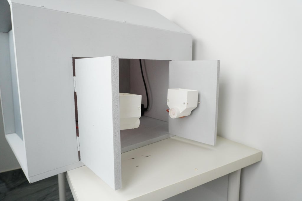
Step 5: Feeder Mechanism & Electronic Enclosure
Creating an efficient and reliable feeder mechanism is crucial for maintaining a consistent feeding schedule for the chickens. We designed a dual-feeder setup using an Archimedes screw mechanism powered by a servo motor, ensuring that food is dispensed smoothly and effectively. Additionally, we developed a protective case for the electronic components housed within the coop, ensuring they are secure and shielded from the elements.
1. Archimedes Screw Feeder Mechanism
The core of the feeding system revolves around the Archimedes screw, a time-tested mechanism known for its ability to move materials smoothly and evenly.
- Archimedes Screw Design: The screw is designed to fit snugly inside a cylindrical housing, allowing it to move the feed upwards and out of the container as it rotates. This mechanism is ideal for controlling the flow of granular or pelletized chicken feed, ensuring that only the right amount is dispensed each time the system is activated.
- Servo Motor Integration: The Archimedes screw is connected to a continuous rotation SG90 servo motor. This motor provides the necessary torque to rotate the screw and move the feed through the system. The servo’s continuous rotation capability allows for precise control over how much feed is dispensed, depending on the duration of the motor’s operation.
- Dual-Feeder Setup: To minimize the risk of food shortages, we implemented a dual-feeder system. Each container is equipped with its own Archimedes screw and servo motor, ensuring redundancy and increasing the availability of food. If one feeder runs low or experiences an issue, the second feeder can continue to provide sustenance, reducing the need for frequent manual refills.Container Lids: Both feeders are topped with securely fitting lids, which help protect the feed from moisture, pests, and contamination. The lids are easy to remove, allowing for quick and straightforward refilling as needed.
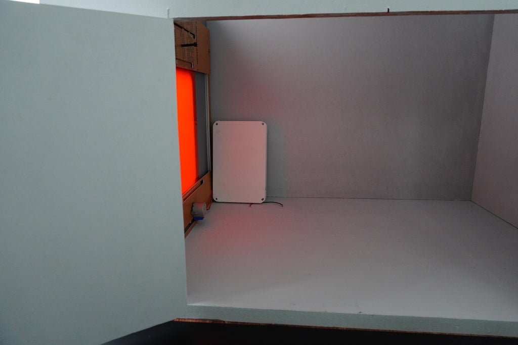
2. Electronics Enclosure
To protect the sensitive electronic components from environmental factors like dust, moisture, and temperature fluctuations, we designed a dedicated enclosure within the coop.
- Enclosure Design: The enclosure is specifically sized to house the Arduino UNO R4 WiFi, motor drivers, buck converter, and wiring. It’s designed with compartments to organize and separate the different components, reducing the risk of interference or short circuits.
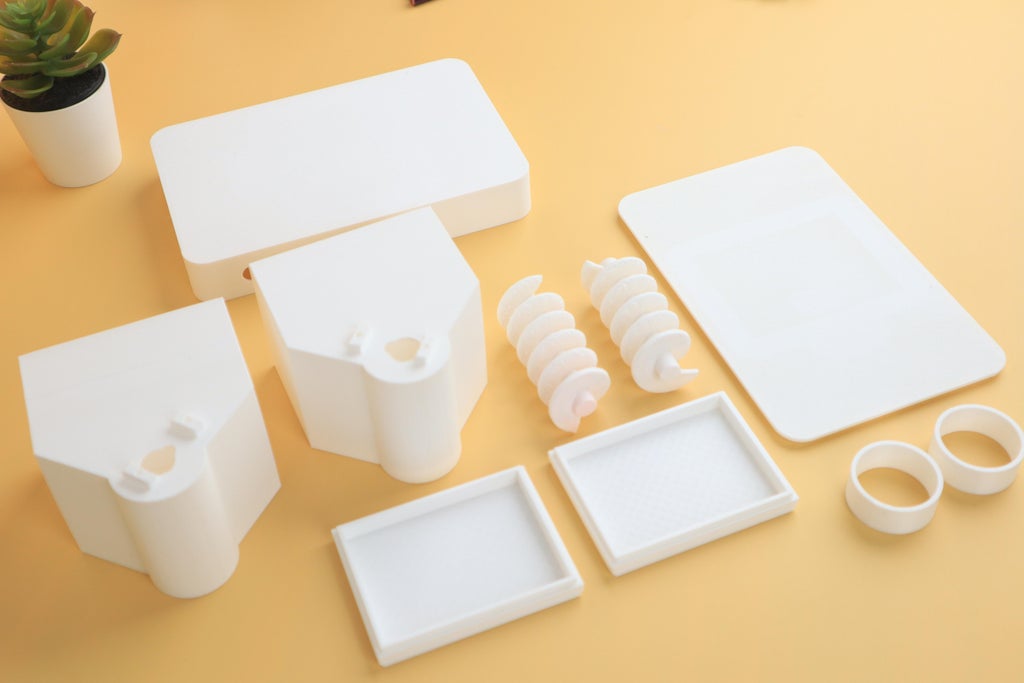
- Material and Printing: The enclosure was modeled in CAD software and exported as an STL file for 3D printing. We chose PLA material for its durability and ease of printing. The enclosure was printed with a 20% infill to balance strength with material usage, ensuring that the case is sturdy enough to protect the components without being overly heavy or material-intensive.
- Ventilation and Access: The enclosure includes small vents to allow for airflow, preventing the electronics from overheating. Additionally, it features access points for wiring and connectors, making it easy to maintain or upgrade the electronics without disassembling the entire case.
3. Assembly and Integration
- Mounting the Feeder Mechanism: The Archimedes screw and servo motors are securely mounted inside each feeder container. The motors are wired to the Arduino control unit, which regulates their operation based on a pre-programmed feeding schedule.
- Installing the Electronics Enclosure: The enclosure is installed in a protected area of the coop, away from the feeding area and any potential exposure to the elements. It is securely fastened to the coop structure, ensuring that it stays in place even in the event of vibrations or movement.
- Wiring: All wiring from the feeders and other components is neatly routed into the enclosure, where it connects to the Arduino and other electronics. This setup not only keeps the wires organized but also protects them from damage or accidental disconnection.
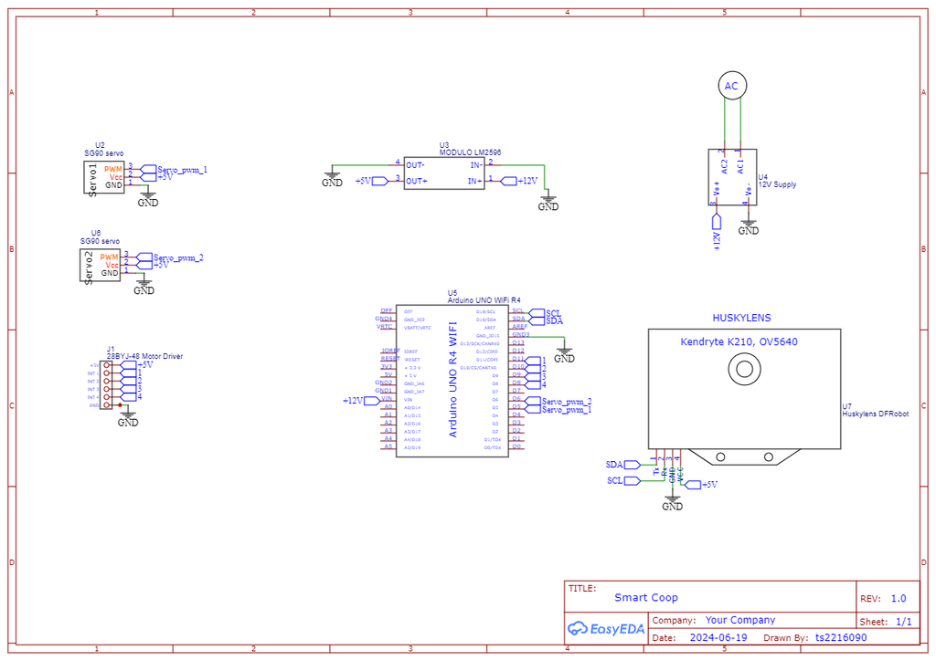
Step 6: Electronics
Integrating the electronics into the smart coop is where the project truly comes to life. Each component is carefully selected and wired to ensure that the coop functions smoothly, automating tasks and keeping the chickens safe. Here's a detailed breakdown of the electronic design:
1. Front Door Mechanism
The front door of the coop is designed to open and close automatically, allowing the chickens to enter and exit at appropriate times. The key components involved in this mechanism include:
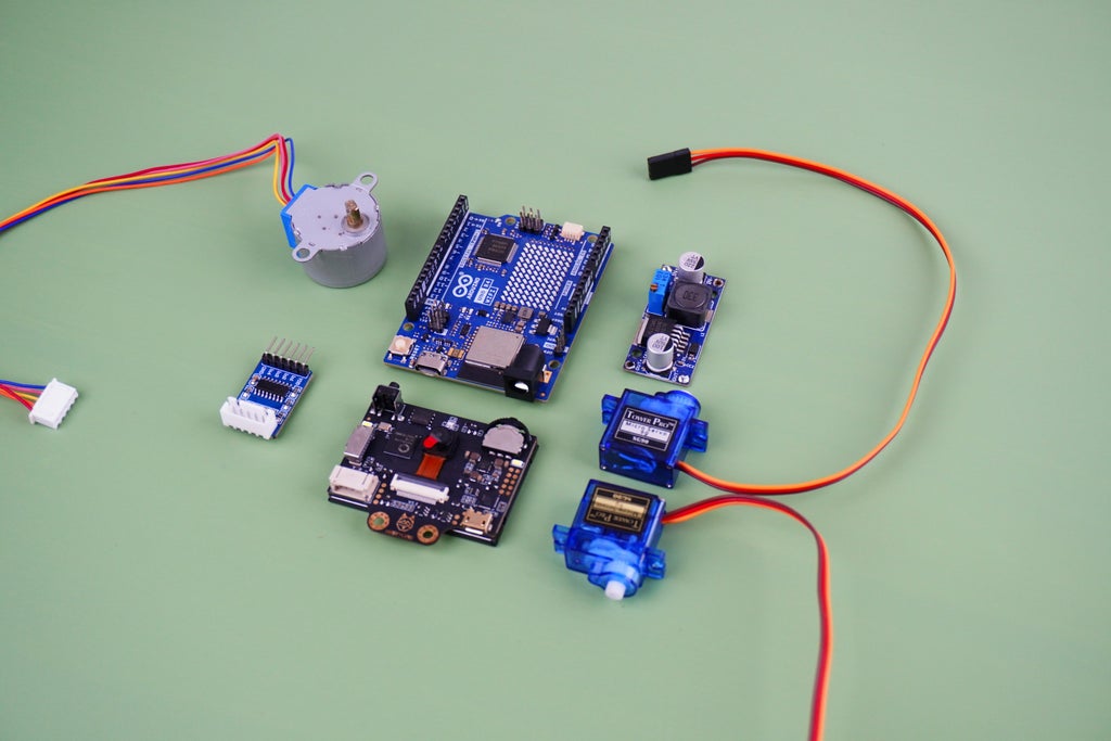
- Stepper Motor: We use a 28BYJ-48 stepper motor to drive the front door. This motor is a common choice for precise control, offering the ability to move in small, accurate steps, which is crucial for the door’s operation.
- Motor Driver: The stepper motor is controlled by a ULN2003 Stepper Motor Driver. This driver board is well-suited for controlling the 28BYJ-48, as it can handle the motor's specific requirements and ensures reliable operation.
- Wiring and Control: The stepper motor is connected to the Arduino UNO R4 WiFi, which sends signals to the ULN2003 driver to control the opening and closing sequences. The Arduino controls the motor based on inputs from sensors or timers, ensuring that the door operates automatically at the correct times.
2. Feeder Mechanism
Automating the feeding process is essential for maintaining a consistent feeding schedule for the chickens. Here's how it’s done:
- Servo Motor: A continuous rotation SG90 servo motor is employed to operate the feeder mechanism. Unlike standard servos, this continuous rotation variant can rotate infinitely in either direction, making it perfect for dispensing feed in a controlled manner.
- Dual-Feeder Setup: The servo motor is connected to a dual-feeder system, allowing it to rotate and dispense feed from two separate containers. This setup ensures that the chickens always have access to food without manual intervention.
- Control: The Arduino UNO R4 WiFi controls the servo motor, rotating it at specified times to release the right amount of feed. This timing can be adjusted based on the chickens’ feeding schedule.
3. Predator Detection
Protecting the chickens from potential predators is a critical aspect of the smart coop’s design. For this, we use:
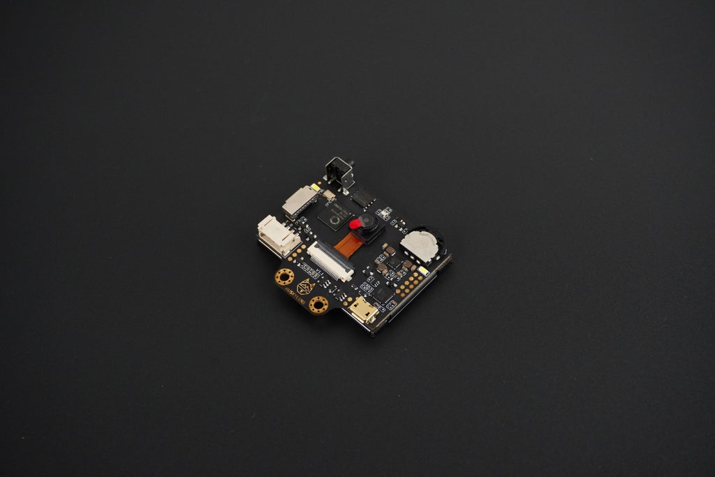
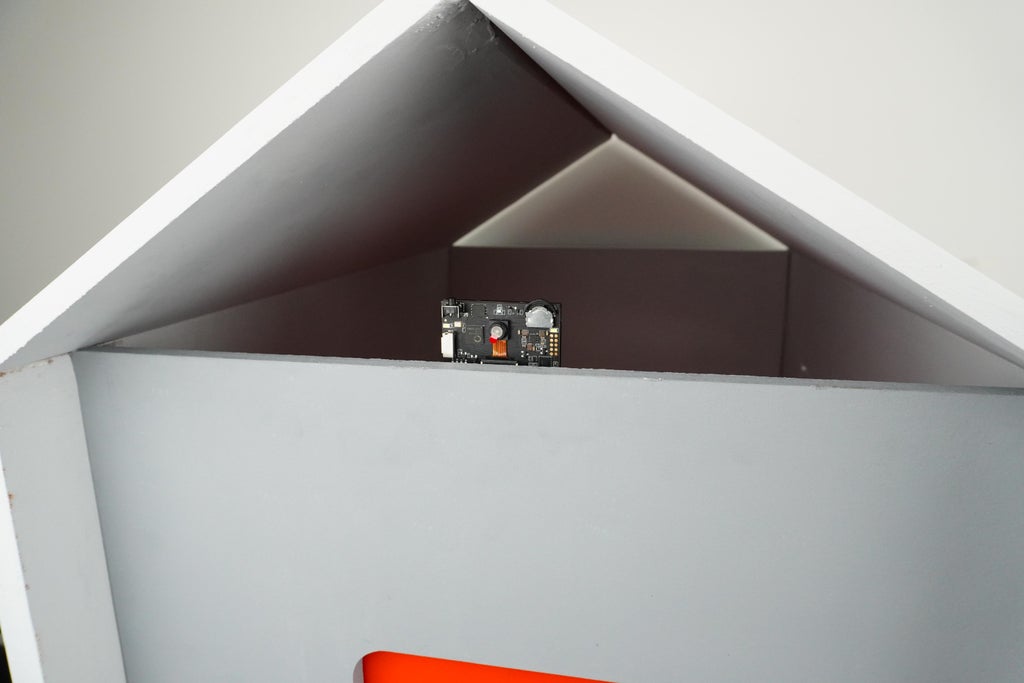
- HuskyLens AI Camera: The HuskyLens is an advanced vision sensor from DFrobot, capable of performing multiple AI functions with ease. In this project, we leverage its object recognition and object tracking features to detect and track potential predators around the coop.
- Functionality: When a predator is detected, the HuskyLens sends a signal to the Arduino, which can then trigger an alert or activate defensive mechanisms. The HuskyLens is configured to recognize specific shapes and movements associated with common predators, providing an extra layer of security for the chickens.
- Integration: The HuskyLens is connected to the Arduino via I2C, a common communication protocol for sensors and microcontrollers. The Arduino processes the data from the HuskyLens and determines the appropriate response.
4. Control Unit
The entire system is coordinated by a central control unit, which is the:
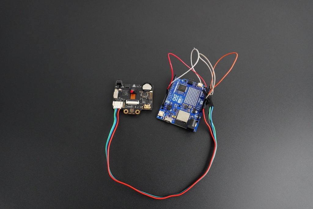
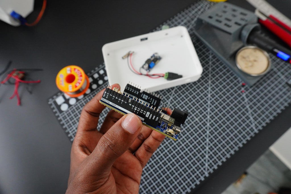
- Arduino UNO R4 WiFi: This microcontroller acts as the brain of the smart coop. It handles all inputs and outputs, processes data from sensors like the HuskyLens, and controls the various motors for the door and feeder mechanisms.
- WiFi Connectivity: The built-in WiFi capability of the Arduino UNO R4 allows for remote monitoring and control. This means you can check the status of the coop, open or close the door, and manage feeding schedules from anywhere with an internet connection.
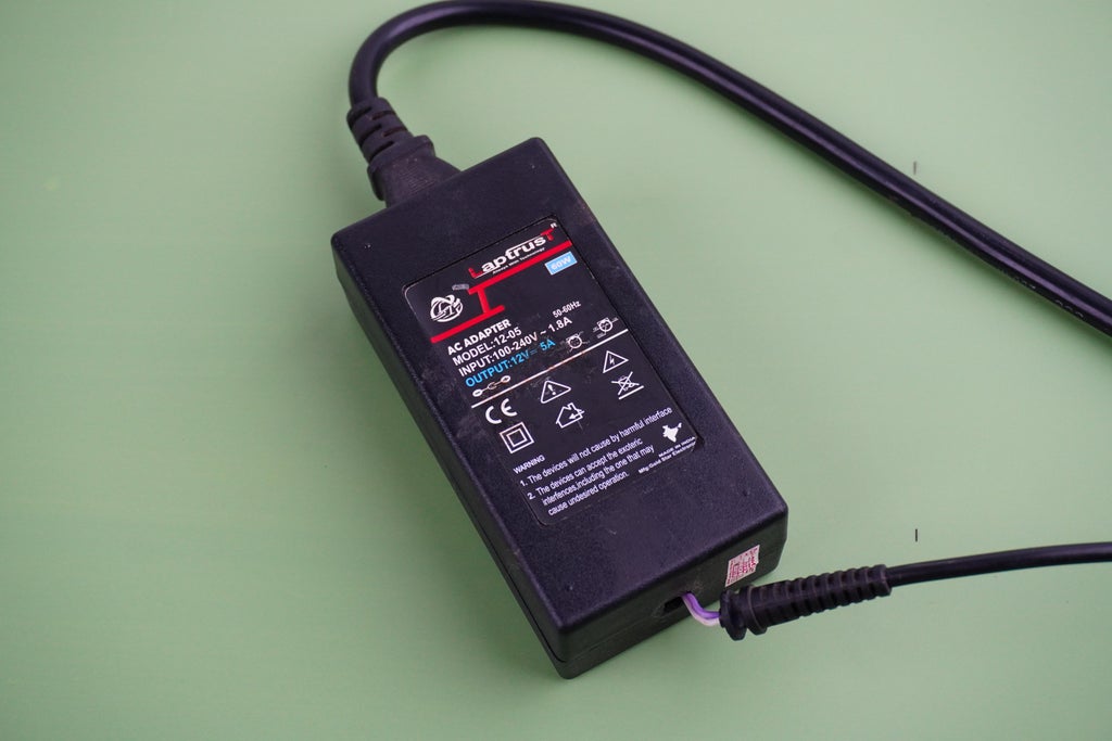
5. Power Supply
Providing a stable power source is essential for the reliable operation of the smart coop. Here’s how we manage the power needs:
- 12V 5A Power Supply: The system is powered by a 12V 5A power supply, which is capable of delivering sufficient current to all components. This power supply is robust enough to handle the load of the stepper motor, servo motor, HuskyLens, and Arduino.
- Voltage Regulation: Since not all components require 12V, we use an LM2596 buck converter to step down the voltage where needed. For example, the HuskyLens and stepper motor operate at lower voltages, so the buck converter ensures they receive the correct voltage without overloading.
Wiring and Integration
- Circuit Design: All components are carefully wired to the Arduino UNO R4 WiFi. The stepper motor driver, servo motor, and HuskyLens are connected to the appropriate pins on the Arduino, with power being distributed through the buck converter as needed.
Step 7: Predator Detection With Husky Lens


Protecting your chickens from predators is a top priority when managing a coop, especially in a farm-to-table setup where the quality and safety of your livestock directly impact your food supply. The HuskyLens, a smart AI vision sensor, offers a powerful solution for predator detection. With its object recognition and facial recognition capabilities, HuskyLens can be programmed to identify potential threats and alert you in real-time, ensuring your flock's safety.
What is HuskyLens?
HuskyLens is an AI-powered vision sensor that can recognize objects, faces, colors, lines, and tags. It's designed to be easy to use, with a user-friendly interface and a built-in screen that allows you to see what the sensor is detecting in real time. HuskyLens is based on machine learning and can be trained to recognize specific objects or creatures, making it an ideal tool for predator detection in a chicken coop. Follow these steps to set up HuskyLens for predator detection
1.Training the HuskyLens:
- Initial Setup:
- Power on the HuskyLens and connect it to your microcontroller.
- Use the menu on the HuskyLens screen to select the object recognition mode.
- Training Process:
- Introduce the HuskyLens to various predators (e.g., raccoons, foxes, stray dogs) in a controlled environment or use images/videos.
- Point the HuskyLens at the predator and press the "learn" button to teach it the specific features of the animal.
- Repeat the process multiple times with different angles and lighting conditions to improve accuracy.
- Recognition Accuracy:
- Test the trained HuskyLens by showing it images or videos of the predator and other animals (like cats, squirrels) to ensure it can differentiate between threats and non-threats.
- Fine-tune the training by adjusting the learning settings if the HuskyLens has trouble distinguishing between animals.
2.Integrating HuskyLens with Your Coop:
- Mounting:
- Place the HuskyLens at a strategic location around your coop, such as near entrances or areas where predators are likely to approach.
- Ensure the HuskyLens has a clear view of the surrounding area and is protected from the elements.
- Connecting to a Microcontroller:
- Use an Arduino Uno R4 to interface with the HuskyLens.
- Program the microcontroller to process the data from HuskyLens and trigger actions, such as sounding an alarm, sending a notification, or activating lights.
- Real-Time Alerts:
- Set up the microcontroller to send notifications to your smartphone or computer when a predator is detected.
- You can also program the system to activate deterrents, like lights or sounds, to scare off predators when they are recognized.
3.Testing and Calibration:
- Testing:
- Monitor the HuskyLens in real-time to see how it responds to potential threats around the coop.
- Make necessary adjustments to the sensitivity or positioning if it fails to detect predators consistently or gives false positives.
- Continuous Learning:
- Continue training the HuskyLens with new images or scenarios as you observe different predators in your area.
- Regularly update the training data to ensure the HuskyLens adapts to changing environments or new threats.
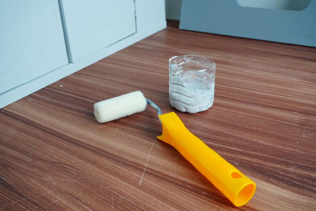
Step 8: Painting
Painting the smart coop not only adds aesthetic appeal but also provides a protective layer that helps the structure withstand the elements. We wanted a durable, attractive finish that would make the coop both functional and visually appealing.
1. Prepping the Wood
Before we even thought about painting, we had to make sure the wood was ready to take on the primer and paint. This step is crucial for getting a smooth, long-lasting finish.
- Cleaning: We started by wiping down the wood to get rid of any dust, dirt, or residue. It’s surprising how much grime can build up, even on new wood, so this step helped to ensure a clean surface for painting.
- Sanding: Next, we sanded the wood lightly. We weren’t going for perfection here, just a smooth enough surface to help the primer stick. Any rough spots or splinters were carefully smoothed out. This gave the wood a nice texture that would hold onto the paint better.
2. Priming the Wood
Priming is the unsung hero of painting projects. It seals the wood, preventing it from soaking up too much paint, and gives the topcoat something to grip onto.
- Choosing the Primer: We used a good-quality wood primer, something that’s built to handle the outdoors. This primer would keep the wood protected from moisture and other elements that could cause damage over time.
- Application: We applied the primer with a standard paintbrush, making sure to cover every inch, especially the edges and corners. After the first coat, we let it dry completely before moving on to the fun part—painting.
3. Mixing the Paint
We had a specific color in mind but didn’t want to spend a fortune on pre-mixed paint. So, we decided to get creative and mix our own.
- Custom Color Creation: We started with a base of white premium emulsion paint and added black stainers little by little until we got the perfect shade of gray. Mixing the color ourselves was a bit of a guessing game, but it was a cost-effective way to get exactly what we wanted.
- Test Patch: Before committing to the color, we brushed a small amount on an inconspicuous part of the coop. It’s always good to test because colors can look different on wood than they do in the can. Fortunately, our mix was spot on.
4. Painting the Coop
With our color ready and the primer dry, it was time to start painting. This is where the coop really started to come to life.
- First Coat: We used roller brushes for the large surfaces. Rolling on the paint gave us a smooth, even finish and made the job go faster. For the corners and edges, we used smaller brushes to make sure we didn’t miss any spots.
- Drying Time: After the first coat, we took a break and let the paint dry completely. This is key to avoiding smudges or uneven layers.
- Second Coat: Once the first coat was dry, we applied a second one. The second coat really made the color pop and added an extra layer of protection. We made sure to cover every spot evenly, ensuring that the coop would be well-sealed against the weather.
- Final Touches: After everything was dry, we did a final check for any missed spots or areas that needed a little more attention. We fixed those up with a small brush, making sure the paint job was perfect.
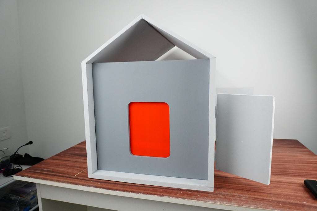
The Finished Look
The final result was exactly what we hoped for—a smooth, even finish in our custom color that not only looked great but also provided a strong, weather-resistant coating for the coop. The time spent on prepping and painting paid off, giving the smart coop a professional look and long-lasting protection.
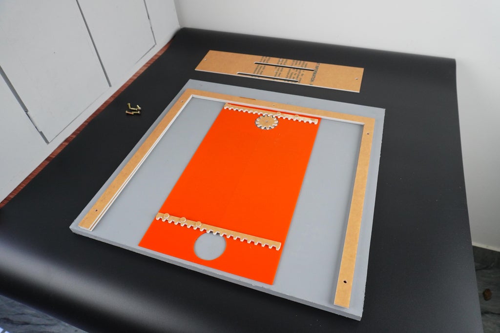
Step 9: Assembling the Automatic Door
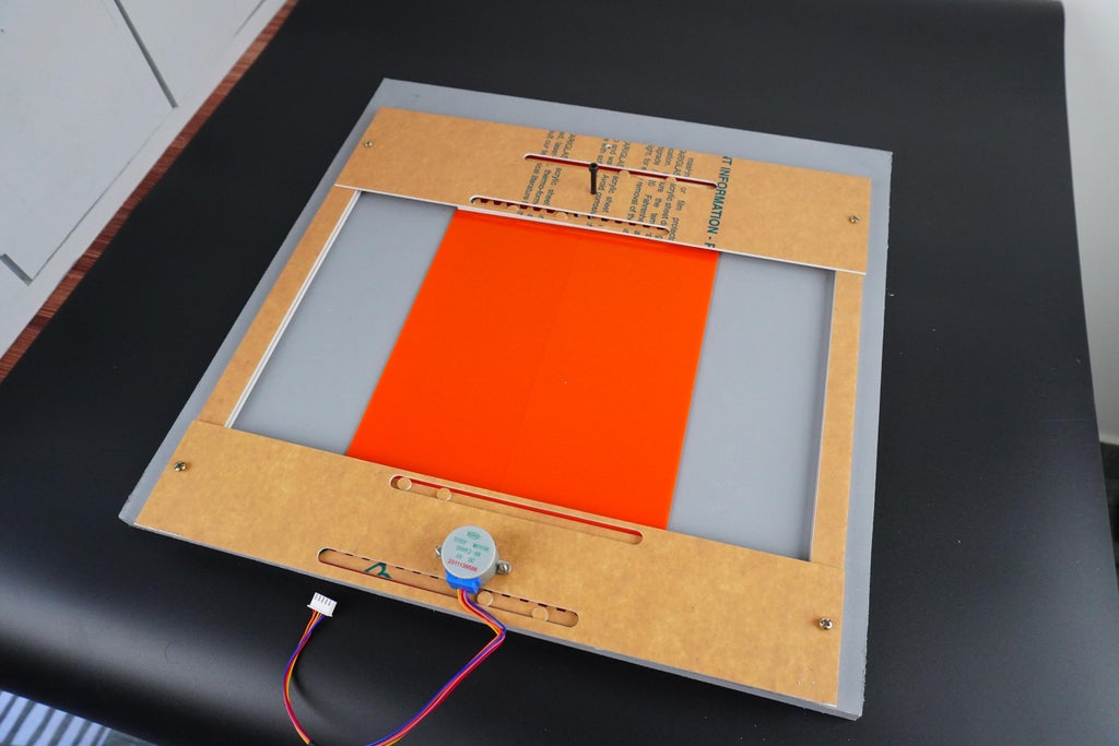
The assembly of the door mechanism for the smart coop involves several precise steps to ensure proper function. Here’s a detailed breakdown of the process:
1.Assembling the Door Mechanism:
- Positioning the Acrylic Pieces: We started by aligning the acrylic components of the door mechanism with the front portion of the coop. These pieces include both the sliding doors and the gears necessary for their operation.
- Securing Acrylic to Wood: Using M4 screws, we securely fastened the acrylic pieces to the wooden frame of the front portion. This ensured a stable and rigid mounting for the mechanism, preventing any movement or misalignment.
2.Attaching the Top Gear:
- Fastening the Gear: The top gear, which is essential for the sliding mechanism, was affixed to its designated position using an Allen bolt. This type of bolt provides a secure fit and allows for precise adjustments if needed.
3.Mounting the Stepper Motor:
- Motor Attachment: The stepper motor, which drives the door mechanism, was attached to the closing plate of the assembly. We used M3 screws for this attachment, ensuring that the motor was firmly secured and aligned correctly to operate the mechanism effectively.
4.Fixing the Front Portion:
- Securing the Front Portion to the Coop: With all components in place, we fixed the entire front portion, including the door mechanism, to the main body of the coop. This step involved aligning the front portion precisely with the coop structure and ensuring a solid attachment.
5.Installing the Front Piece:
- Final Assembly: Finally, we installed the front piece onto the coop, integrating it with the rest of the structure. This involved making sure that all components were correctly aligned and that the sliding door mechanism operated smoothly.
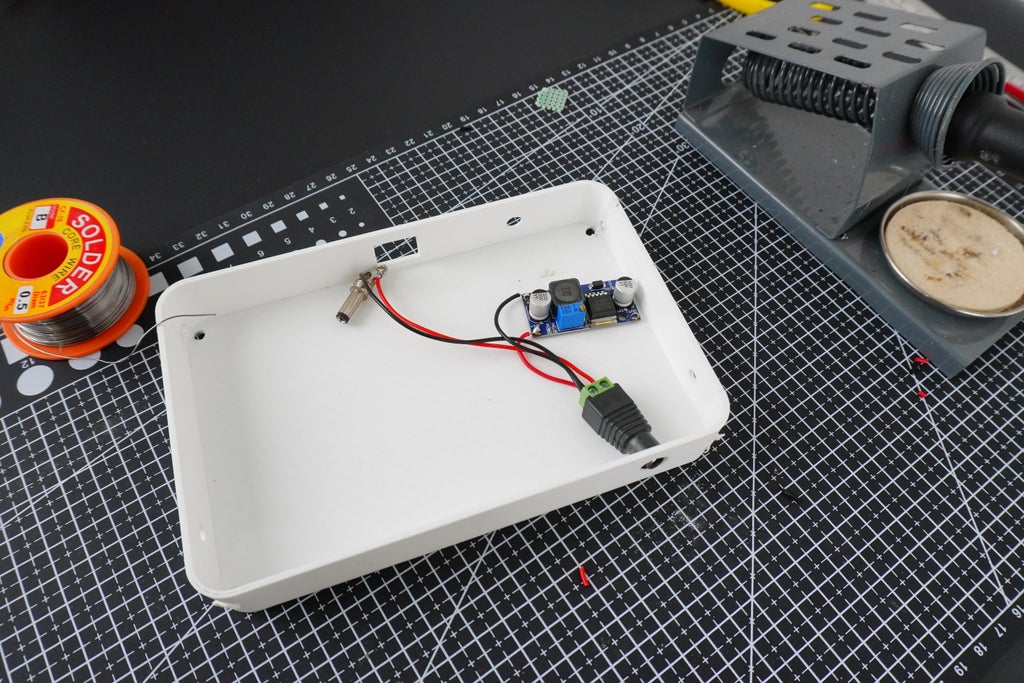
Step 10: Electronics Setup
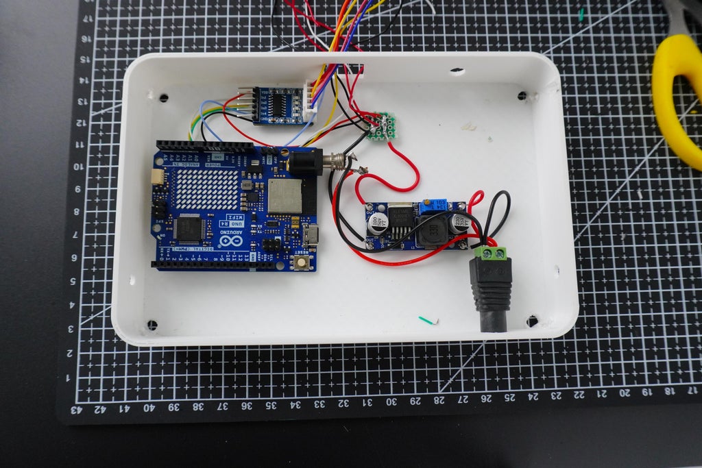
The setup of the electrical components involved careful connection and configuration to ensure reliable operation of the smart coop’s systems. Here’s a detailed description of the process:
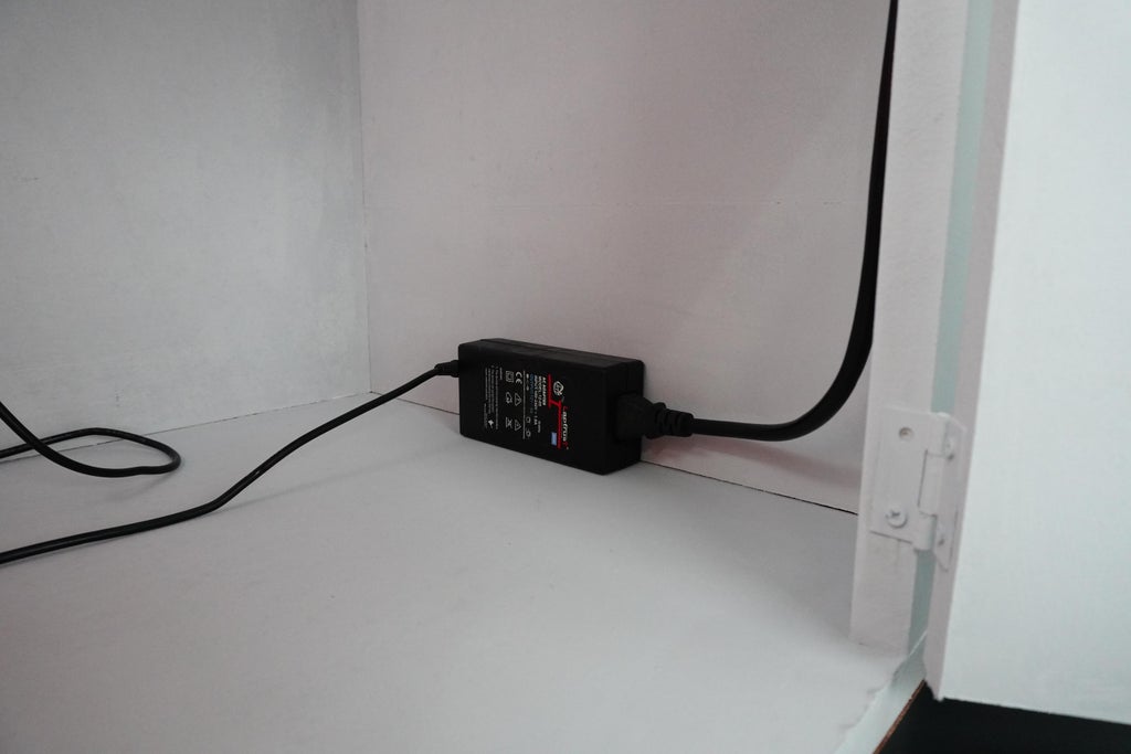
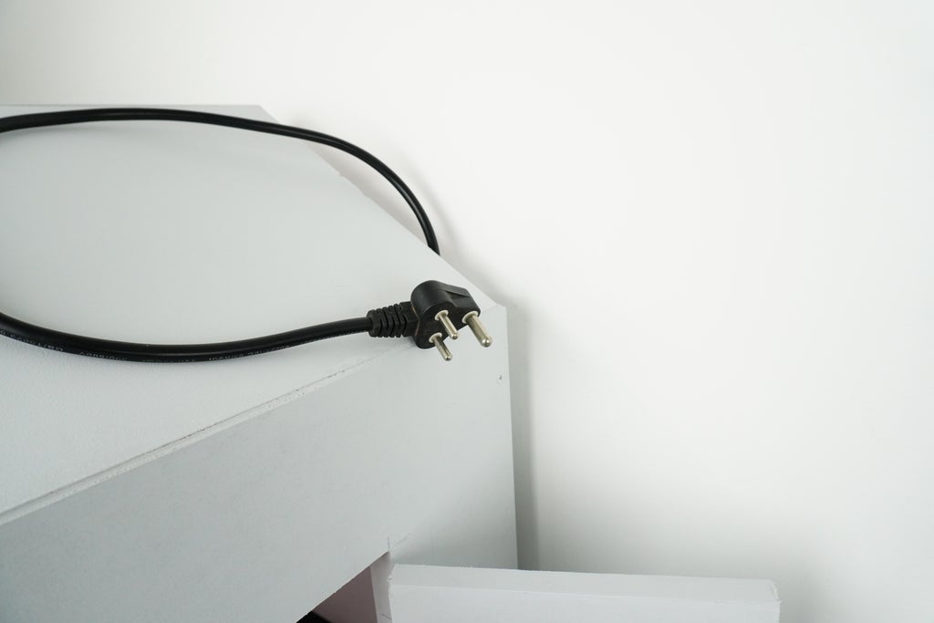
1.Connecting the Power Supply:
- 12V Power Supply: We began by connecting the 12V power supply to the system. To achieve this, we used a DC female jack, which provided a secure and stable connection for the power input. This jack was wired to the 12V power source, ensuring that the entire system receives the necessary voltage.
2.Powering the Arduino:
- Male Jack for Arduino: For powering the Arduino, we used a male jack. This jack was connected to the Arduino’s power input port, enabling the board to receive power from the 12V supply through the appropriate connections.
3.Setting Up the LM2596 Buck Converter:
- Voltage Adjustment: The LM2596 buck converter was used to step down the voltage from 12V to 5V. We adjusted the output voltage of the buck converter by turning the potentiometer on the device. This precise adjustment ensured that the components requiring 5V, such as the servo motor, HuskyLens, and stepper motor, received the correct voltage for proper operation.
4.Creating a 5V Power Rail:
- Perf Board Setup: We created a small perf board to establish a dedicated 5V power rail. This board was used to distribute 5V power to multiple components within the system. The power rail ensured that the servo motor, HuskyLens, and stepper motor received a stable 5V supply, which is critical for their performance and reliability.
- Power Distribution: On the perf board, we connected the output from the LM2596 buck converter to the power rail. This setup allowed us to efficiently distribute the 5V power to each of the components, ensuring consistent and reliable operation.
Step 11: Final Assembly
The installation of the electronics and feeder units inside the smart coop involves careful placement and secure mounting to ensure optimal performance and stability. Here’s a detailed description of each step:
1.Installing the Electronics Enclosure:
- Positioning the Enclosure: We started by placing the electronics enclosure inside the smart coop. This enclosure houses the various electronic components, including the Arduino, LM2596 buck converter, and any additional wiring necessary for the system.
- Securing the Enclosure: To ensure that the electronics enclosure remained firmly in place, we used masking tapeto secure it inside the coop. The tape provided a temporary but effective hold, preventing movement and vibration that could potentially disrupt the electronics.
2.Connecting the Power Supply:
- Mounting the 12V Power Supply: Next, we positioned the 12V power supply near the electronics enclosure. We used masking tape to affix the power supply securely to a convenient location inside the coop. This placement ensured easy access and stable mounting while keeping the power supply out of the way of other components.
- Pulling the AC Wire: We then pulled the AC wire from the power supply to an external power source. This wire was routed carefully to avoid any interference with other components or mechanical parts, ensuring a clean and safe connection.
3.Attaching the Feeder Units:
- Mounting the Feeder Units: We completed the assembly by attaching the two feeder units to the designated locations within the coop. Using M3 x 40mm screws, we secured each feeder unit firmly in place. These screws provided a solid attachment, ensuring that the feeder units remained stable and operational during use.
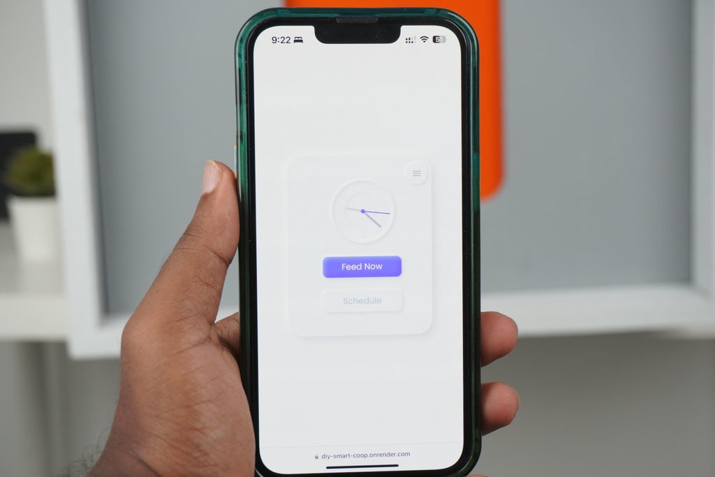
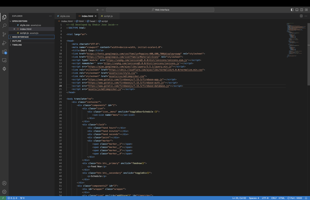
Step 12: Companion App

We have developed a companion app to remotely control and manage the smart coop, enhancing its automation and user convenience. The app provides several key features:
- Feed Now Button: This feature allows users to dispense feed instantly with a single tap, ensuring that chickens receive food promptly as needed.
- Feeding Schedule: Users can set up to three feeding schedules, automating the feeding process according to predefined times. This ensures consistent and timely nourishment for the chickens.
- Instant Door Control: A dedicated button enables users to open the coop door immediately, providing easy access or ventilation as required.
- Door Scheduling: The app includes a scheduler for the automatic opening and closing of the door in the morning and evening. This helps regulate the coop’s environment and manage the chickens' daily routine efficiently.
Technical Details
- Website Development: The app’s interface is built using HTML, CSS, and JavaScript, offering a responsive and user-friendly experience.
- Firebase Integration: The app uses Firebase JS to handle communication with Firebase, allowing for real-time updates and synchronization of the app’s features with the smart coop’s operations.
Step 13: Twilio for Setting SMS Alert
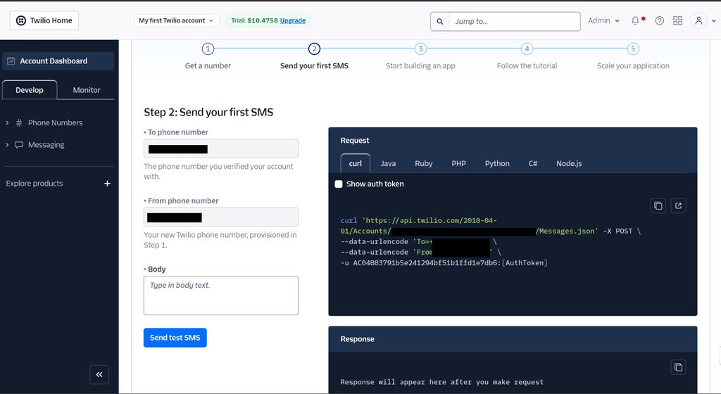

Twilio is a cloud communications platform that provides a set of APIs (Application Programming Interfaces) for building and integrating communication services into applications. It allows developers to add messaging, voice, and video capabilities to their applications without having to build or maintain complex infrastructure.
Here we are using Twilio to send SMS alerts if there are any predators detected.
Follow these steps carefully for integrating Twilio
1) Signup for Twilio, if you don't have an account
2) Get a Twilio Phone number, this phone number will be used for sending the SMS alert to the concerned person.
3) Then note the account info such as the Account SID, Auth Token and the generated Twilio number, this should need to be added in the code.
Step 14: Code
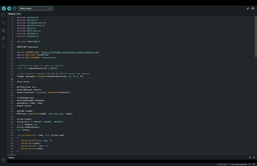
To bring our smart coop to life, we wrote a custom code that integrates all the key functionalities. The code, running on the Arduino UNO R4 WiFi, manages the automated door system, feeder mechanism, and predator detection. We utilized libraries for controlling the stepper motor, servo motor, and HuskyLens AI camera. The code also includes logic for the scheduling system, which allows the companion app to send commands for feeding times and door operations. Using the Firebase library, we ensured seamless communication between the app and the coop, allowing for real-time control and monitoring from anywhere.
Step 15: Smart Coop Is Ready for Action

Simply plug in your smart coop, and it’s ready to handle all your chicken care needs. From automated feeding and secure door control to real-time predator detection, this fully finished smart coop has everything set up for you. Just sit back and let your coop do the work!
Step 16: Assets for Replication
Within this GitHub repository, you'll discover all the resources necessary to replicate this project. If you've any doubts, feel free to ask them in the comments, we're here to help.
This article was first published on Aug 9th, 2024 on Instructables
cr: https://www.instructables.com/50-DIY-AI-Smart-Coop/
Author: CodersCafeTech


 DFR0868DFR0706-ENSEN0501SEN0193DFR0063DFR0888-12DFR0981DFR0478DFR0658SEN0321SEN0170SEN0471DFR0058FIT0895SEN0305ROB0128DFR0305DFR0282DFR0745FIT0502DFR0554DFR0558FIT0585DFR0181FIT0793DFR0937DFR0439DFR0759SEN0304DFR0483DFR0868DFR0706-ENSEN0501SEN0193DFR0063DFR0888-12DFR0981DFR0478DFR0658SEN0321SEN0170SEN0471DFR0058FIT0895SEN0305ROB0128DFR0305DFR0282DFR0745FIT0502DFR0554DFR0558FIT0585DFR0181FIT0793DFR0937DFR0439DFR0759SEN0304DFR04833162


