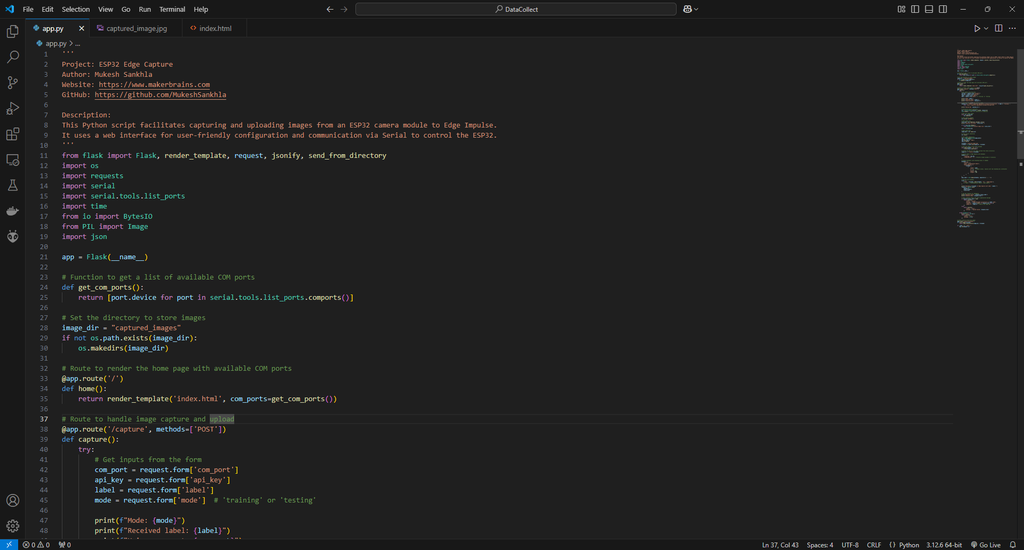
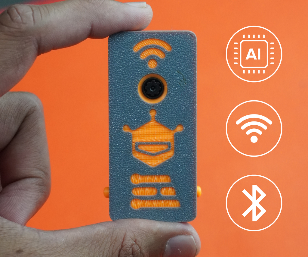
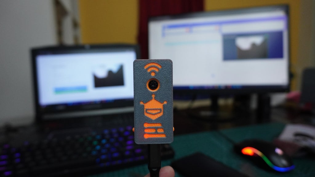
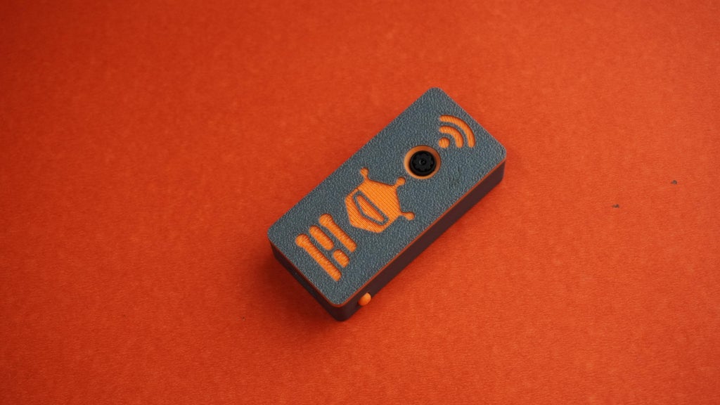
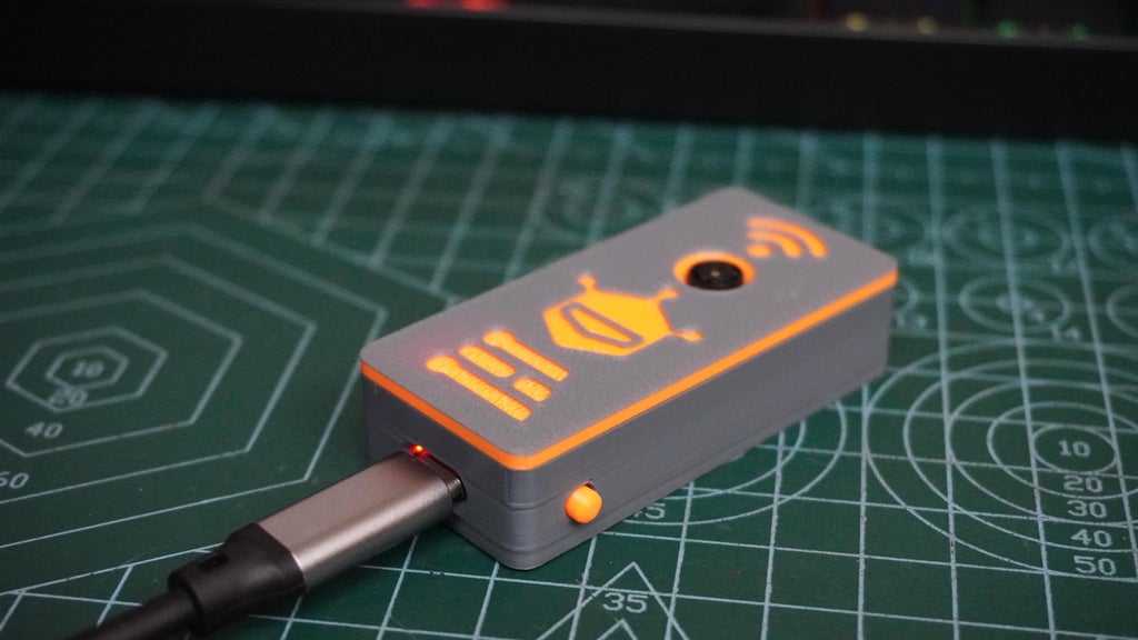
 In this project, I'll walk you through creating an ESP32 Edge AI Camera system that simplifies data collection and model deployment for AI tasks. This system combines the power of the ESP32-S3 microcontroller with a camera module and a 3D-printed magnetic case, making it compact, portable, and easy to mount on various surfaces.
*The unique feature of this project is the streamlined data capture and upload process to Edge Impulse. Using a custom-built Arduino code for the ESP32 and a Python-based web interface running on Flask, you can quickly collect, preview, and upload labeled image data to Edge Impulse.
Here's how it works:
*Run the Python web interface and connect to the ESP32 via USB.
*Enter your Edge Impulse API key, select Training or Testing, and optionally specify a label for the images.
*Click the Capture and Upload button.
*The ESP32 receives the command via USB, captures an image, and sends it back to the PC.
*The image is saved, previewed on the web interface, and uploaded to Edge Impulse with the desired settings.
*This system eliminates the manual tasks of connecting SD cards, transferring images, and labeling data, making it perfect for rapid prototyping and dataset generation.
*By the end of this project, you'll learn how to:
*Capture data using an ESP32 camera.
*Train an Edge Impulse model with the collected data.
*Deploy the trained model back onto your ESP32 for real-time AI inference.
Supplies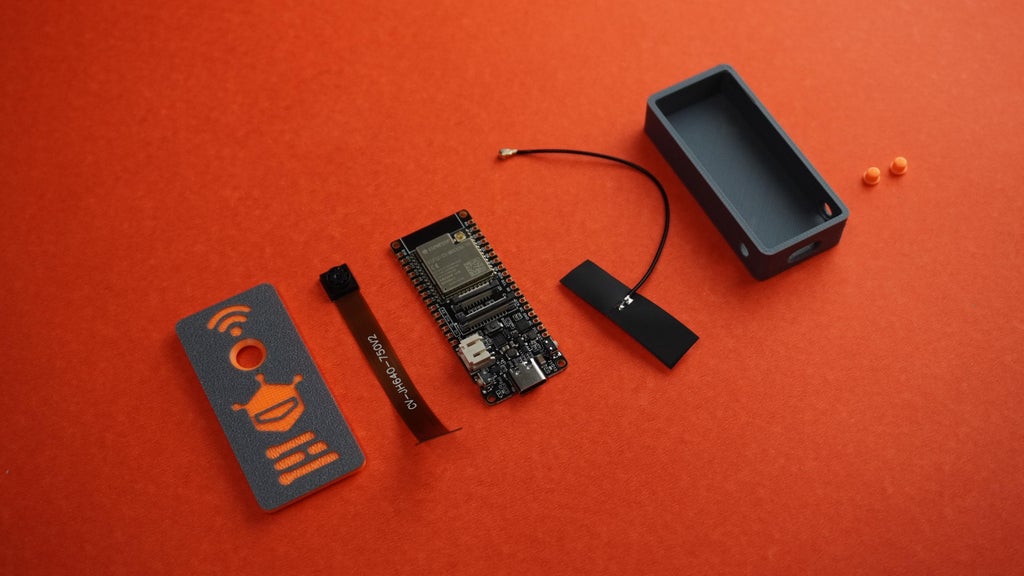
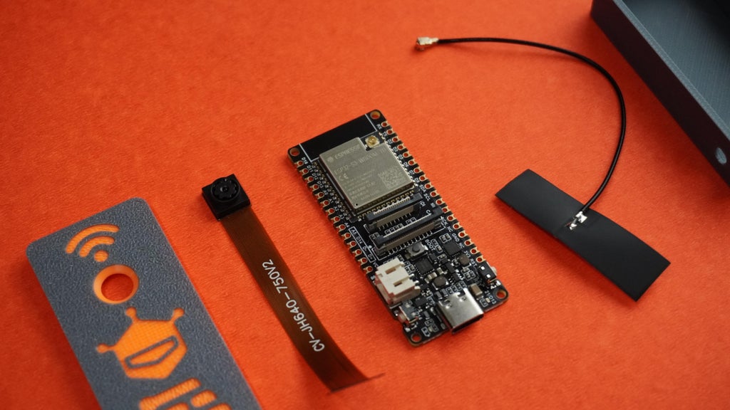
1x FireBeetle 2 Board ESP32-S3 or FireBeetle 2 Board ESP32-S3 With External Antenna
8x 5mm Magnets
1x Quick Glue
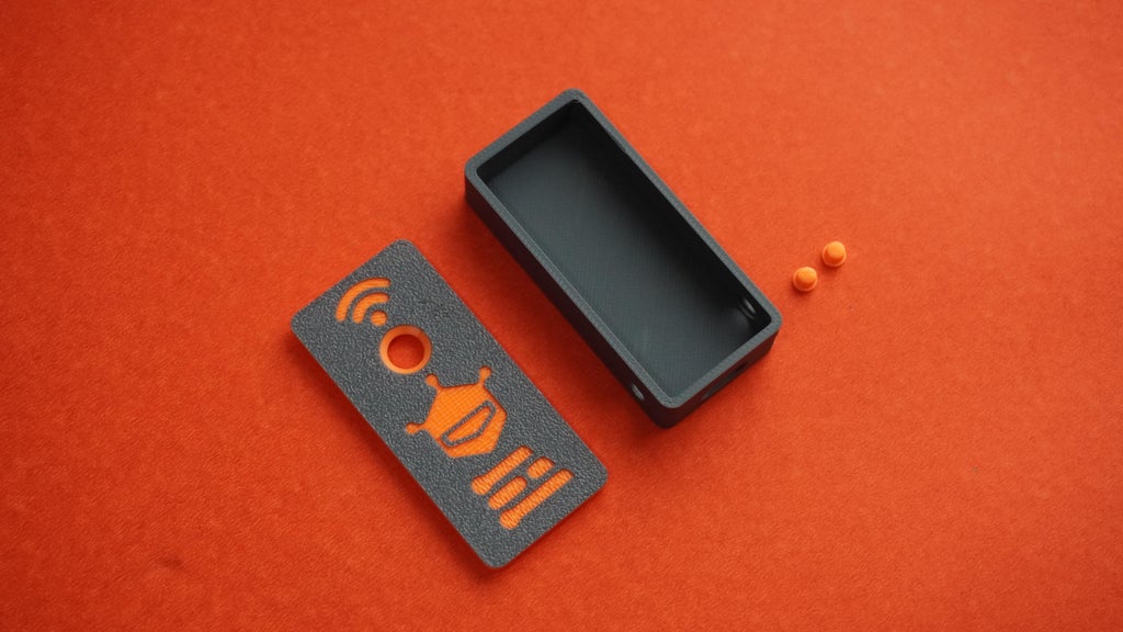
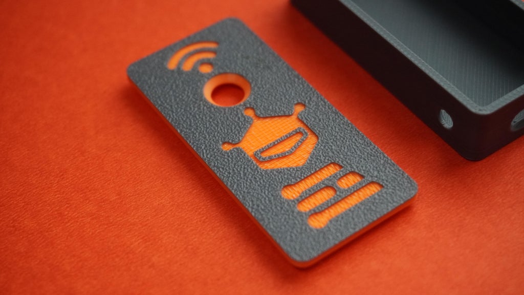
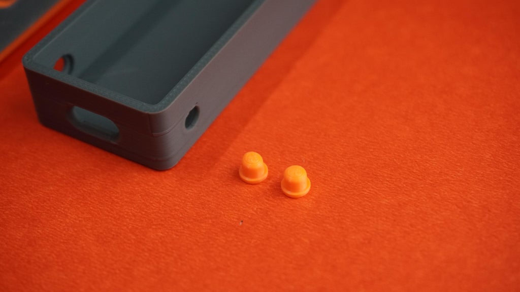
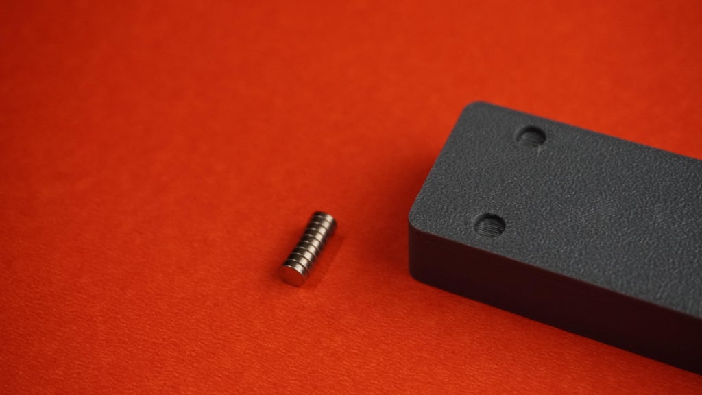
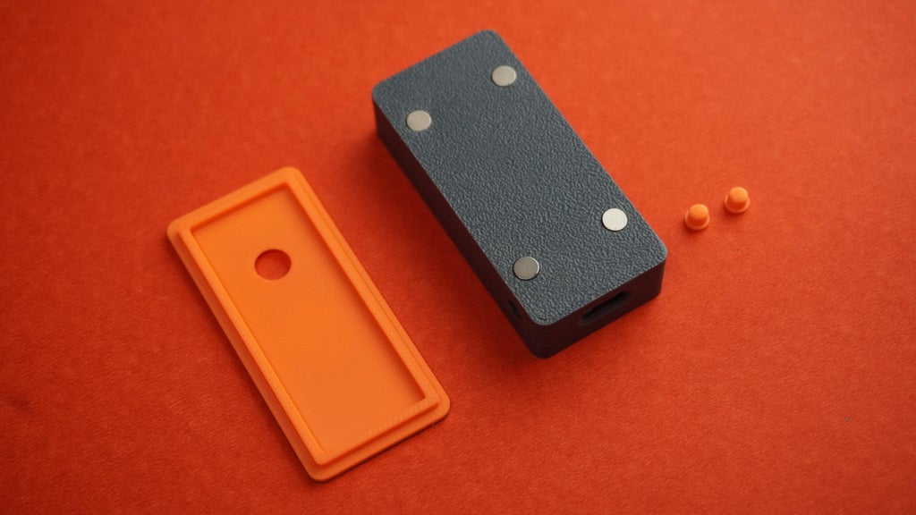 *To begin, I designed a custom case for the ESP32-S3 camera using Fusion 360. The design includes:
*A magnetic mounting system for easy attachment.
*Extensions for the side buttons, allowing access to the Reset button and a programmable button.
*You can either modify the design using the provided Fusion 360 file or directly download and *3D print the following parts:
*1x Housing.stl
*1x Cover.stl
*2x Button.stl
*1x Plate.stl
*Additionally, I've included a simple mounting plate in the design. You can customize it or create your own to suit your needs.
*I printed the case using Gray and Orange PLA filament on my P1S. For the cover, I used a filament change technique to achieve a two-tone color effect. This adds a unique touch to the design while maintaining the functional integrity of the case.
ESP32 Edge Capture
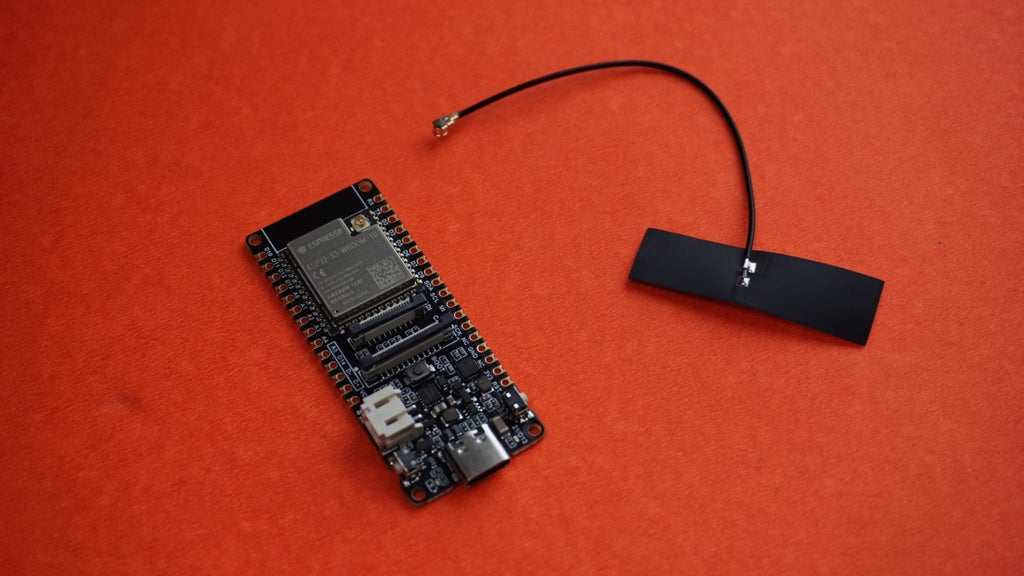
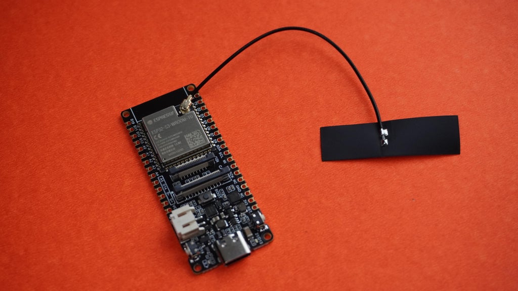 Simply connect the antenna that comes with the ESP32-S3 to the designated port on the ESP32-S3 board.
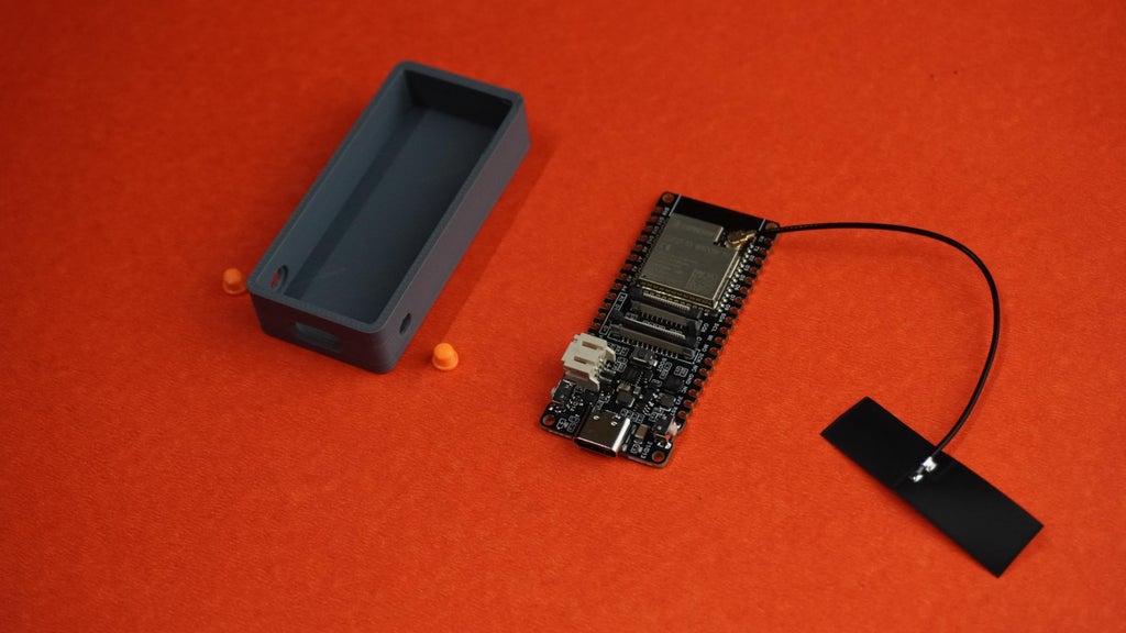
 *Take the 3D printed housing and the two button extensions.
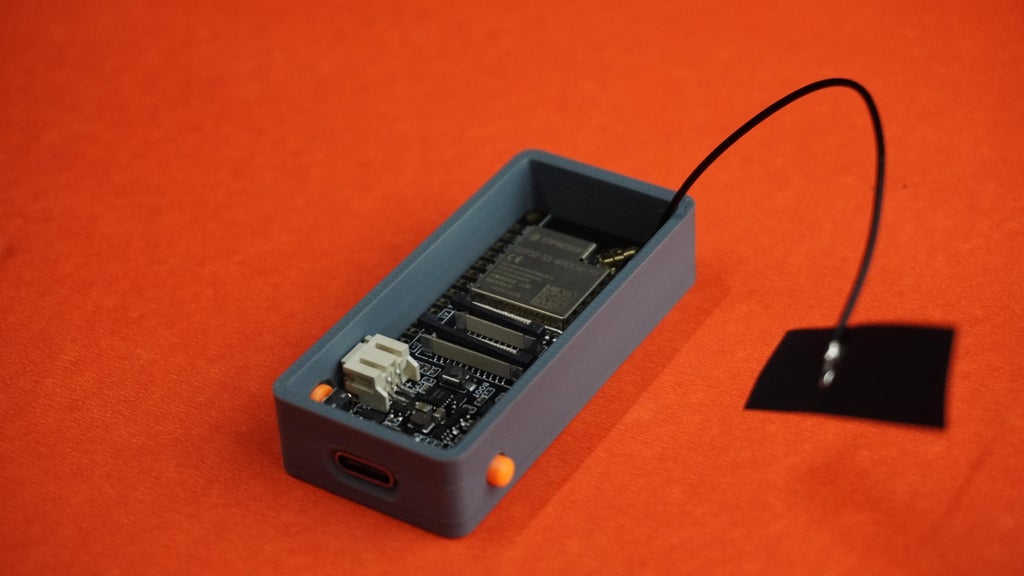
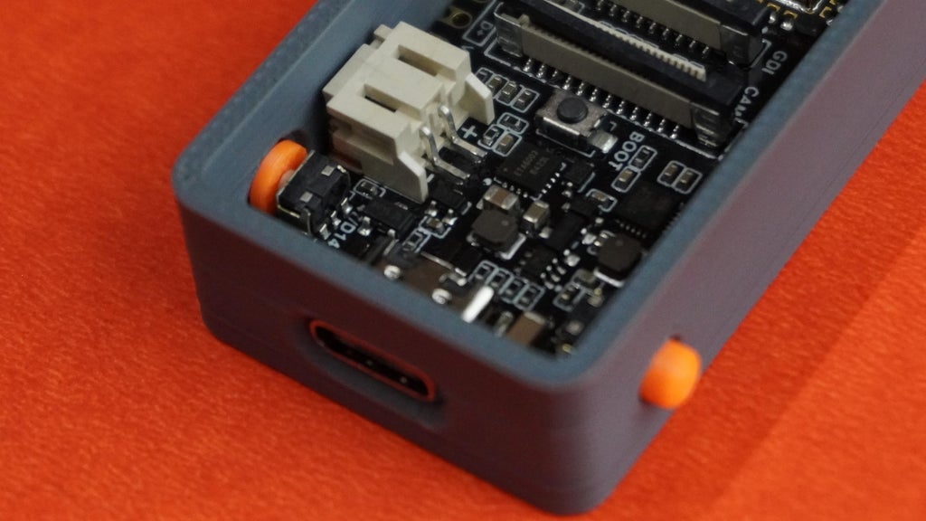
*Insert the buttons into their designated slots on the housing.
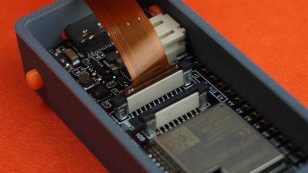
*Place the ESP32-S3 board inside the housing, making sure the Type-C port aligns with the opening in the case.
*Take the camera module included with the ESP32-S3, the 3D printed cover, and quick glue.
*Carefully apply a small amount of quick glue to the camera module.
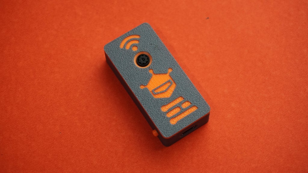
*Attach the camera module to the hole on the cover and ensure it is correctly oriented and securely positioned. Be cautious with the glue to avoid any contact with the lens or delicate parts of the camera.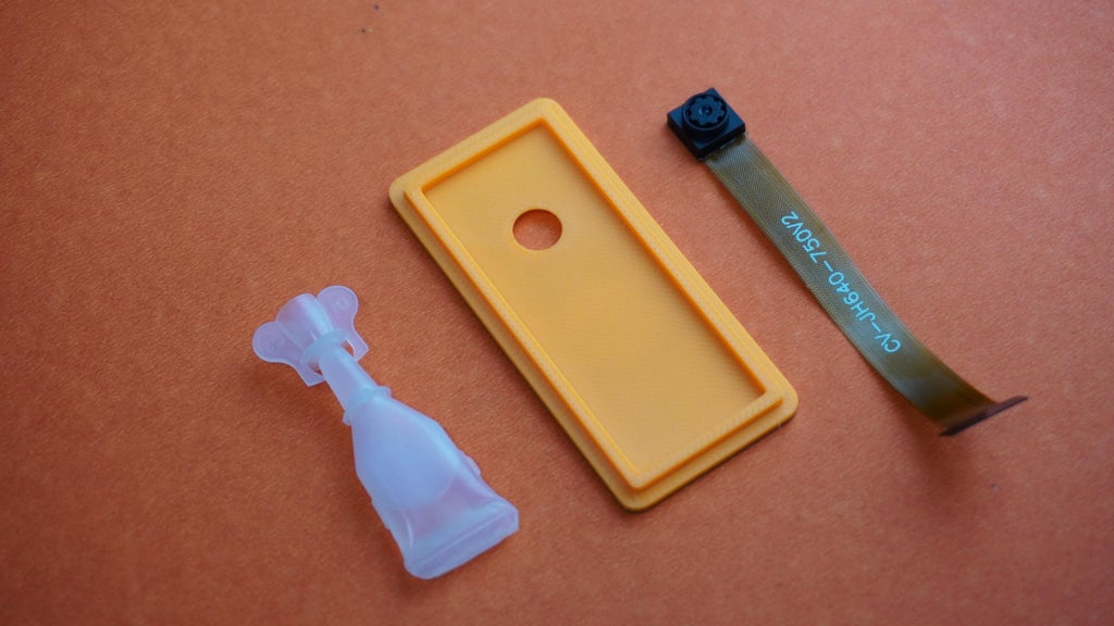
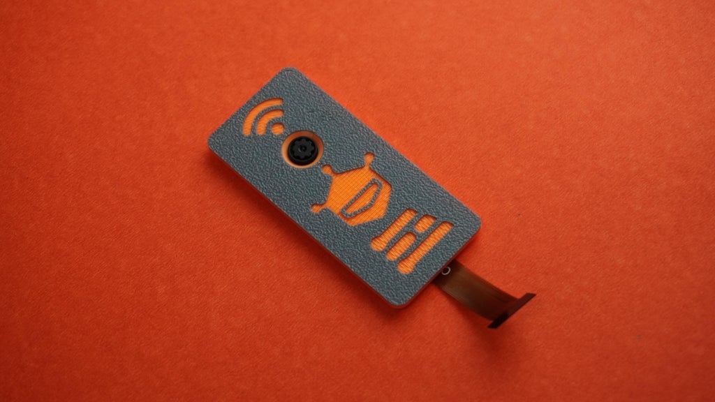
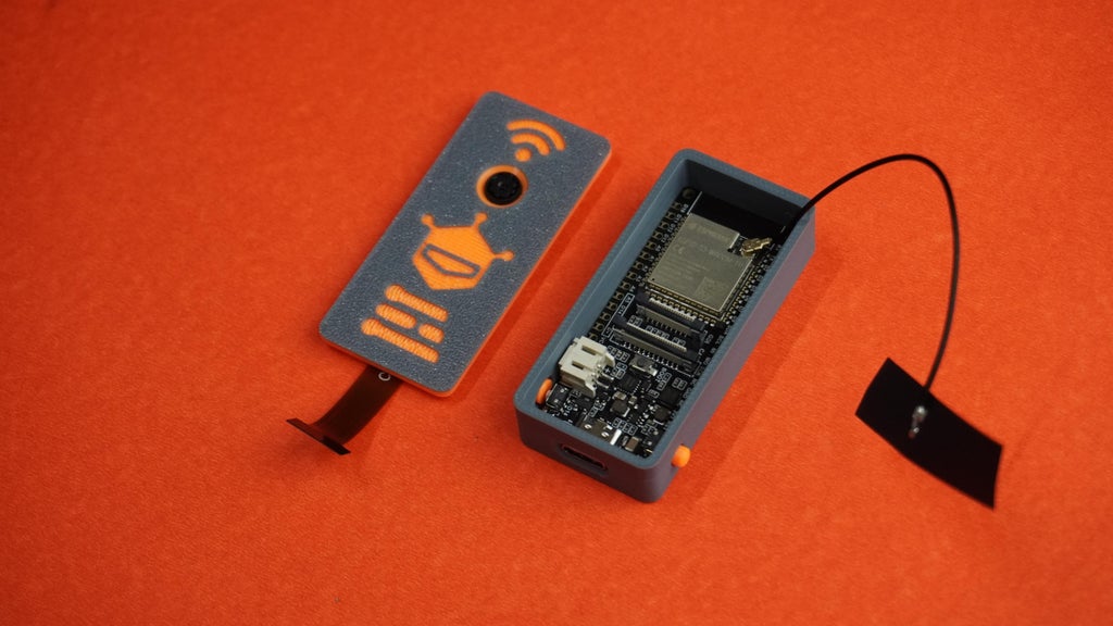
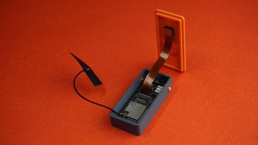
 *Take the housing assembly and the cover assembly.
*Connect the camera module cable to the ESP32 board.
*Neatly tuck the antenna wire and camera cable inside the housing to ensure nothing is pinched or obstructed.
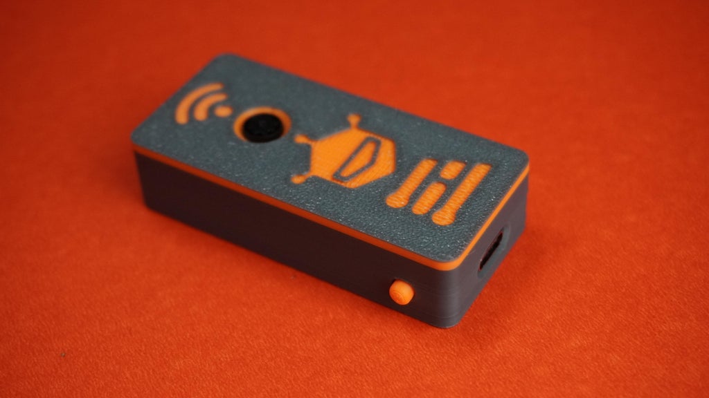
*Snap the cover onto the housing to close it securely.
*Your ESP32 Edge AI Camera is now fully assembled.
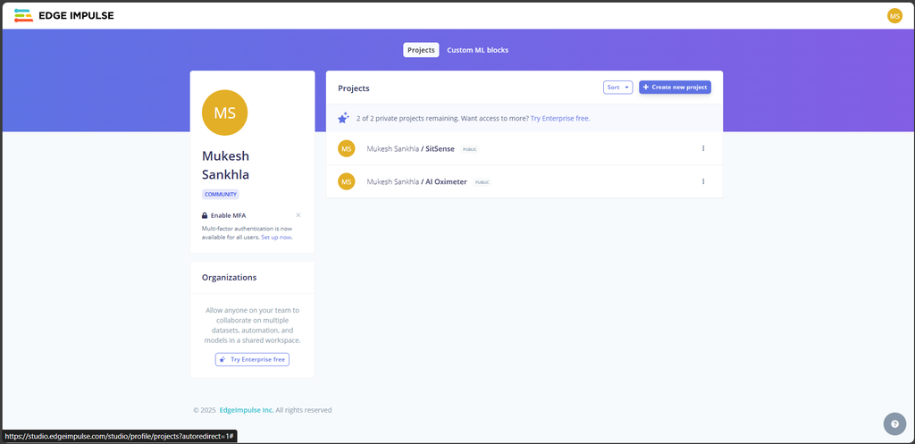
 1. Create an Edge Impulse Account
*Go to edgeimpulse.com and log in to your account.
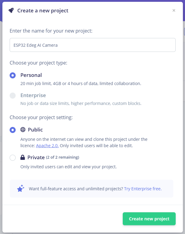
*Click on "Create new project."
*Enter a name for your project.
*Choose whether to keep your project Private or Public.
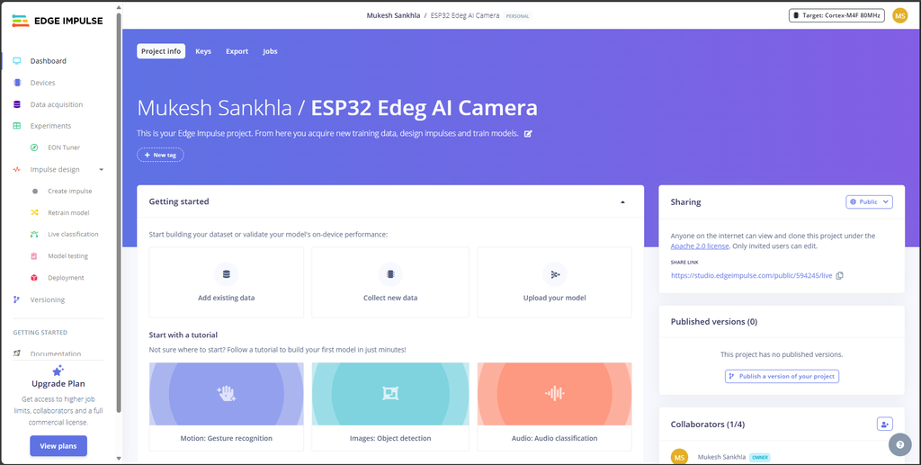
*Click on "Create".
What is Edge Impulse
*Edge Impulse is a platform designed for building, training, and deploying machine learning models on edge devices like microcontrollers and embedded systems. It simplifies the process of working with data, creating ML models, and deploying them directly to your hardware.
*The key features of Edge Impulse include:
*Data Collection and Management: Gather and label your data efficiently.
*Model Training: Train custom machine learning models tailored to your use case.
*Deployment: Deploy the trained model to edge devices with optimized performance.
Data Acquisition Panel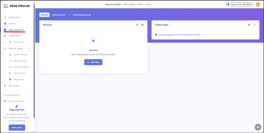
*The Data Acquisition Panel in Edge Impulse is where you upload and manage your data. Here's how it works:
*You can upload images, audio, or sensor data directly from your device or through integrations like APIs.
*Data can be organized into training and testing sets for effective model evaluation.
*Labels can be added to your data, helping Edge Impulse understand and categorize the input.
*Live data acquisition is also supported via connected devices, which simplifies gathering real-time input.
*Types of Data and How to Collect Them
*You can upload pre-collected data, such as images, audio, or sensor readings, directly to the platform.
*The Edge Impulse Data Forwarder allows you to send live data from connected devices like the ESP32 directly to the platform.
*Use the Edge Impulse API to programmatically upload data from external sources.
1. Download the Code
*GitHub Repository: Download the full repository
*Extract the files and locate the ESP32_Code.ino file in the project folder.
*Open Arduino IDE on your computer.
*Navigate to File > Open and select the ESP32_Code.ino file from the extracted folder.
2. Install ESP32 Board Manager
*If you haven't already configured the ESP32 environment in Arduino IDE, follow this guide:
*Visit: Installing ESP32 Board in Arduino IDE.
*Add the ESP32 board URL in the Preferences window:
https://raw.githubusercontent.com/espressif/arduino-esp32/gh-pages/package_esp32_index.json
*Install the ESP32 board package via Tools > Board > Boards Manager.
3. Install Required Libraries
*You need to install the following libraries for this project:
*DFRobot_AXP313A Library
*Download DFRobot_AXP313A
*In Arduino IDE, go to Sketch > Include Library > Add .ZIP Library and select the downloaded DFRobot_AXP313A.zip file.
4. Upload the code
*Connect the ESP32 Edge AI Camera to PC using Type-C USB cable.
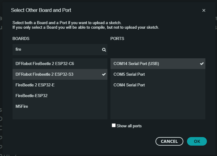
*Go to Tools and set up the following:
*Board: Select DFRobot FireBeetle 2 ESP32-S3.
*Port: Select the COM port associated with your ESP32 board.
*Click the Upload button (right arrow) in the Arduino IDE
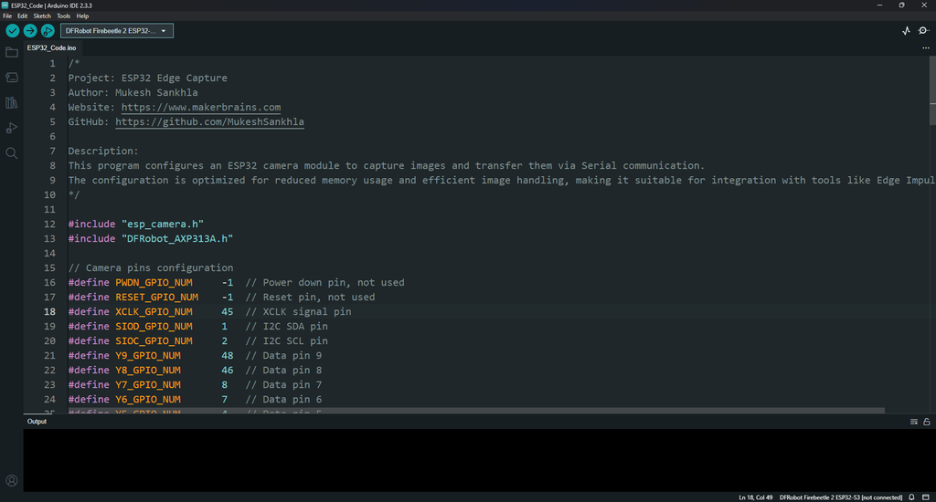
/*
Project: ESP32 Edge Capture
Author: Mukesh Sankhla
Website: https://www.makerbrains.com
GitHub: https://github.com/MukeshSankhla

Description:
This program configures an ESP32 camera module to capture images and transfer them via Serial communication.
The configuration is optimized for reduced memory usage and efficient image handling, making it suitable for integration with tools like Edge Impulse.
*/

#include "esp_camera.h"
#include "DFRobot_AXP313A.h"

// Camera pins configuration
#define PWDN_GPIO_NUM     -1  // Power down pin, not used
#define RESET_GPIO_NUM    -1  // Reset pin, not used
#define XCLK_GPIO_NUM     45  // XCLK signal pin
#define SIOD_GPIO_NUM     1   // I2C SDA pin
#define SIOC_GPIO_NUM     2   // I2C SCL pin
#define Y9_GPIO_NUM       48  // Data pin 9
#define Y8_GPIO_NUM       46  // Data pin 8
#define Y7_GPIO_NUM       8   // Data pin 7
#define Y6_GPIO_NUM       7   // Data pin 6
#define Y5_GPIO_NUM       4   // Data pin 5
#define Y4_GPIO_NUM       41  // Data pin 4
#define Y3_GPIO_NUM       40  // Data pin 3
#define Y2_GPIO_NUM       39  // Data pin 2
#define VSYNC_GPIO_NUM    6   // Vertical sync signal pin
#define HREF_GPIO_NUM     42  // Horizontal reference signal pin
#define PCLK_GPIO_NUM     5   // Pixel clock signal pin

DFRobot_AXP313A axp;  // Power management IC instance

void setup() {
  // Initialize Serial communication
  Serial.begin(921600); // Higher baud rate for faster image transfer

  // Initialize the AXP313A power management IC
  while (axp.begin() != 0) {
    Serial.println("AXP313A initialization failed");
    delay(1000);
  }

  // Enable power for the OV2640 camera
  axp.enableCameraPower(axp.eOV2640);

  // Configure the camera
  camera_config_t config;
  config.ledc_channel = LEDC_CHANNEL_0;
  config.ledc_timer = LEDC_TIMER_0;
  config.pin_d0 = Y2_GPIO_NUM;
  config.pin_d1 = Y3_GPIO_NUM;
  config.pin_d2 = Y4_GPIO_NUM;
  config.pin_d3 = Y5_GPIO_NUM;
  config.pin_d4 = Y6_GPIO_NUM;
  config.pin_d5 = Y7_GPIO_NUM;
  config.pin_d6 = Y8_GPIO_NUM;
  config.pin_d7 = Y9_GPIO_NUM;
  config.pin_xclk = XCLK_GPIO_NUM;
  config.pin_pclk = PCLK_GPIO_NUM;
  config.pin_vsync = VSYNC_GPIO_NUM;
  config.pin_href = HREF_GPIO_NUM;
  config.pin_sscb_sda = SIOD_GPIO_NUM;
  config.pin_sscb_scl = SIOC_GPIO_NUM;
  config.pin_pwdn = PWDN_GPIO_NUM;
  config.pin_reset = RESET_GPIO_NUM;
  config.xclk_freq_hz = 20000000;  // 20 MHz clock frequency
  config.frame_size = FRAMESIZE_VGA;  // Frame size: 640x480
  config.pixel_format = PIXFORMAT_JPEG;  // Image format: JPEG
  config.grab_mode = CAMERA_GRAB_WHEN_EMPTY;
  config.fb_location = CAMERA_FB_IN_DRAM;  // Store frame buffer in DRAM
  config.jpeg_quality = 12;  // Adjust image quality (lower = better quality)
  config.fb_count = 1;  // Single frame buffer

  // Initialize the camera
  esp_err_t err = esp_camera_init(&config);
  if (err != ESP_OK) {
    Serial.printf("Camera initialization failed with error 0x%x\n", err);
    return;
  }

  // Configure additional camera settings for optimized performance
  sensor_t *s = esp_camera_sensor_get();
  if (s) {
    s->set_brightness(s, 1);     // Slightly increase brightness
    s->set_contrast(s, 1);       // Slightly increase contrast
    s->set_saturation(s, -2);    // Reduce saturation
    s->set_special_effect(s, 0); // Disable special effects
    s->set_whitebal(s, 1);       // Enable white balance
    s->set_awb_gain(s, 1);       // Enable auto white balance gain
    s->set_wb_mode(s, 0);        // Auto white balance mode
    s->set_gainceiling(s, (gainceiling_t)GAINCEILING_2X);
  }

  Serial.println("READY");  // Indicate the camera is ready
}

void loop() {
  // Check for Serial commands
  if (Serial.available()) {
    String command = Serial.readStringUntil('\n');

    if (command == "CAPTURE") {
      // Capture an image
      camera_fb_t *fb = esp_camera_fb_get();
      if (!fb) {
        Serial.println("ERROR");  // Notify if the capture failed
        return;
      }
      delay(100);
      esp_camera_fb_return(fb);  // Return the frame buffer to free memory
      delay(100);

      // Send the image size to the Serial
      Serial.println(fb->len);
      delay(100);  // Allow time for size transmission

      // Transmit the image data via Serial
      Serial.write(fb->buf, fb->len);
      delay(100);  // Allow time for data transmission
    }
  }
  delay(10);  // Short delay to reduce CPU usage
}Mount the Camera:
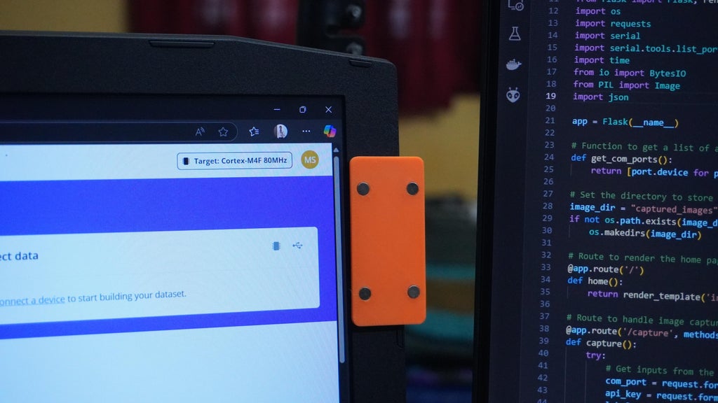
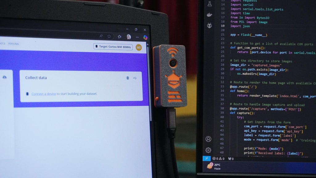
*Attach the magnetic mounting plate to your laptop or desired surface using double sided tape.
*Mount the AI camera onto the plate and connect it to your PC using a USB cable.
Prepare the Code:
*Open the downloaded project folder in VS Code.
*Ensure that Python 3 is installed on your system.
*Install the required Python modules by running:
pip3 install -r requirements.txt
Run the Web Interface:
*Start the Flask web application by running:
python app.py
*Open your web browser and navigate to the default address: http://localhost:5000.
Using the Web Interface
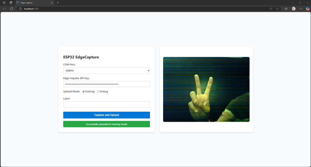
*Choose the COM port where your ESP32 camera is connected.
*Enter your Edge Impulse API key to enable data uploads.
*Select Train mode to collect training data.
*Select Test mode to gather test data.
*Enter a label for your dataset (Optional).
*Click the Capture and Upload button to capture an image using the ESP32.
*Captured by the camera.
*Previewed in the web interface.
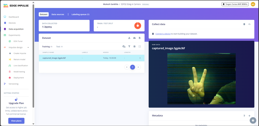
*Uploaded to Edge Impulse with the specified label and mode.
*When a label is provided, a bounding box will be drawn around the image with the given label name:
files = [
('data', (filename, open(filepath, 'rb'), 'image/jpeg'))
]

if label:
# Prepare metadata (with bounding boxes if needed)
metadata = {
"version": 1,
"type": "bounding-box-labels",
"boundingBoxes": {
filename: [
{
"label": label,
"x": 0, # Full image bounding box coordinates
"y": 0,
"width": 640,
"height": 480
}
]
}
}
bbox_label = json.dumps(metadata, separators=(',', ':'))

# Add label data to files
files.append(('data', ('bounding_boxes.labels', bbox_label)))
*This is useful when the object of interest occupies the entire image, as the bounding box defaults to cover the entire image resolution.
*However, if you leave the label field empty, no bounding box will be drawn, and the image will not have a label assigned.
*To demonstrate the capabilities of the ESP32 Edge AI Camera, we'll create a simple project: Finger Counter with ESP32 AI Camera. This project will detect the number of fingers shown in front of the camera and output the corresponding count (e.g., showing one finger will result in "Count 1").
Data Collection
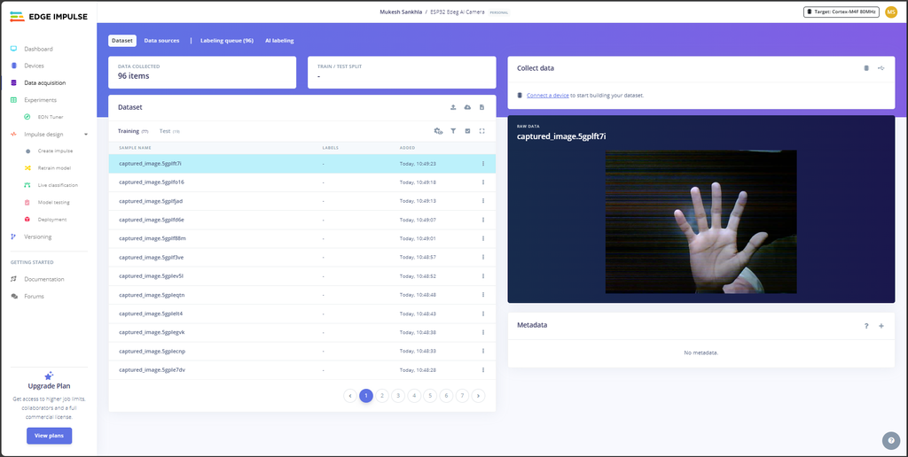
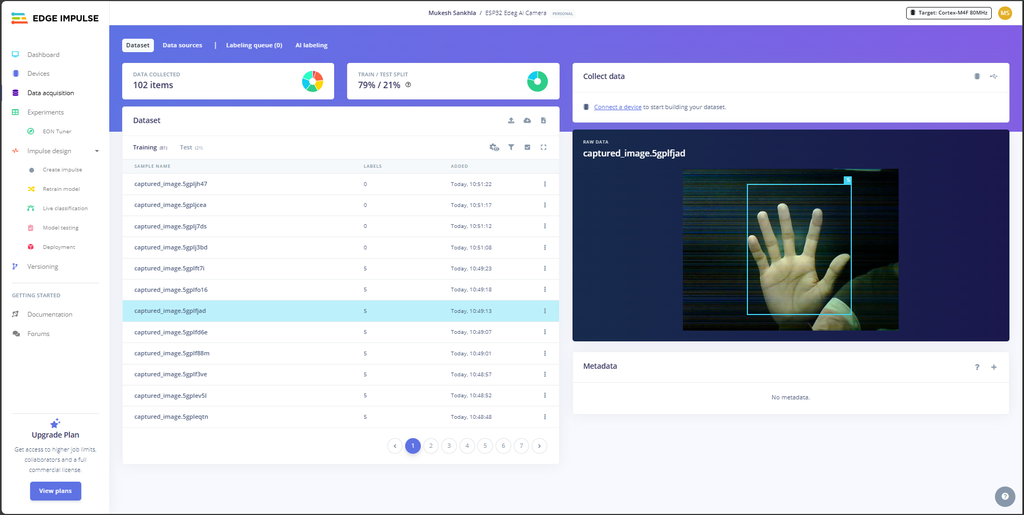
*Use the ESP32 Edge Capture system to collect images for the training and testing datasets.
*Capture as many images as possible to ensure accuracy. A good rule of thumb is to maintain a 5:1 ratio between training and testing datasets (e.g., for every 50 training images, collect 10 testing images).
*Include a variety of lighting conditions, angles, and backgrounds to make the model robust.
Dataset Examples
*One Finger: Capture images with one finger raised.
*Two Fingers: Capture images with two fingers raised.
*Continue capturing images for three, four, and five fingers.
*Include some empty images (no fingers shown) to represent a "zero count."
*This step ensures that the model has sufficient data to learn and perform well during real-time inference.
Labeling the Dataset
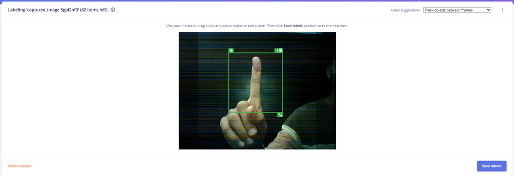
*After collecting all the images, it's time to label them in Edge Impulse. Follow these steps:
*Go to the Labeling Queue section.
*Label each image according to the number of fingers shown
*Double-check each labeled image to ensure accuracy, as incorrect labels can reduce the model's performance.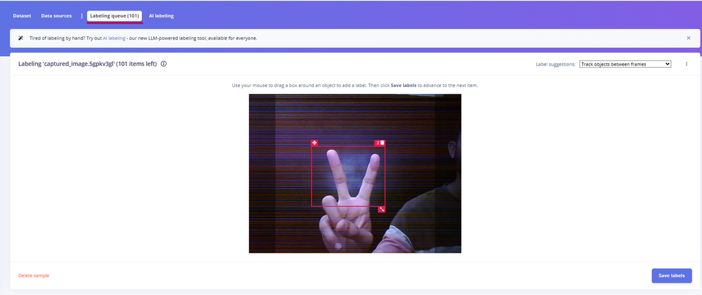
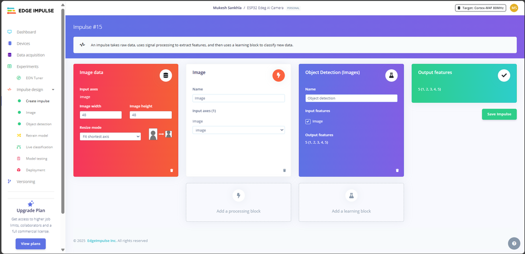 Navigate to the "Impulse Design" section in Edge Impulse.
Set up the Image Data block with:
*Input axes: Image
*Image width: 48 pixels
*Image height: 48 pixels
*Resize mode: Fit shortest axis
*Add an Object Detection block under Learning Blocks.
*Input Feature: Select the Image block.
*Output Features: Define the labels as 1, 2, 3, 4, 5.
*Once configured, click Save Impulse.
Set Processing Parameters:
*Under the Parameters section:
*Ensure the Image Color Depth is set to Grayscale or another value suitable for your use case.
*Click Save Parameters to apply the settings.
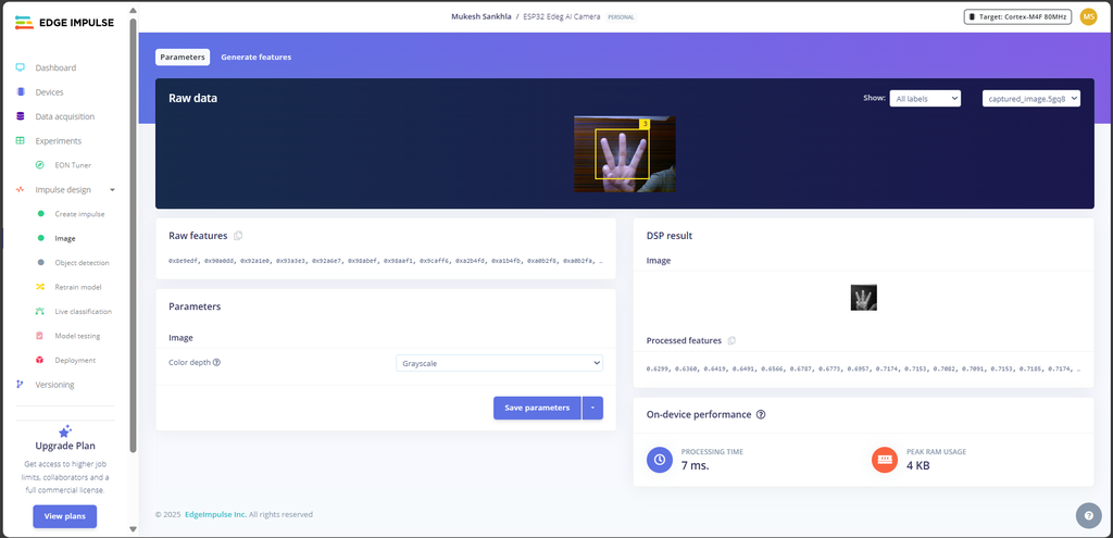
Generate Features:
*Switch to the Generate Features tab.
*Review the summary of the training dataset:
*Data in training set: Number of items (e.g., 64 items as shown in the screenshot).
*Classes: Check the labels/classes associated with your dataset (e.g., 1, 2, 3, 4, 5).
*Click the Generate Features button to process the data.
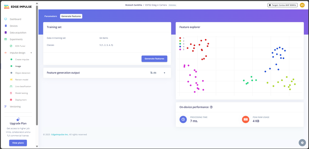
Analyze Feature Output:
*After processing, view the Feature Explorer on the right side of the page.
*The scatter plot in the Feature Explorer visualizes how different classes are separated based on the generated features.
*Each color corresponds to a specific class.
*Ensure the features are well-separated for each class; this indicates the dataset is suitable for training.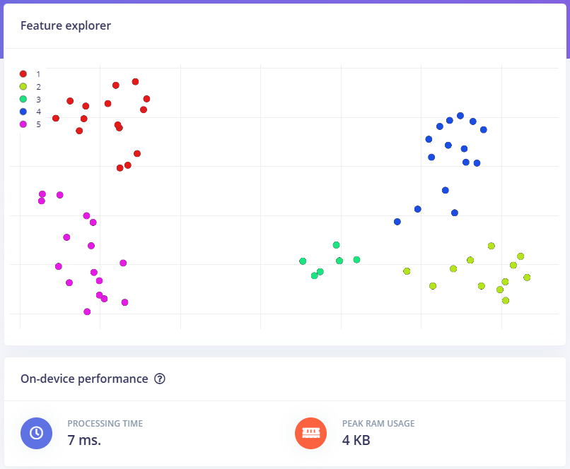
Navigate to Object Detection:
*In Edge Impulse, go to Impulse Design > Object Detection.
Set Training Parameters:
*Number of Training Cycles: 30
*Learning Rate: 0.005
*Training Processor: Select CPU
*Enable Data Augmentation: Check the box for data augmentation (recommended for improving model generalization).
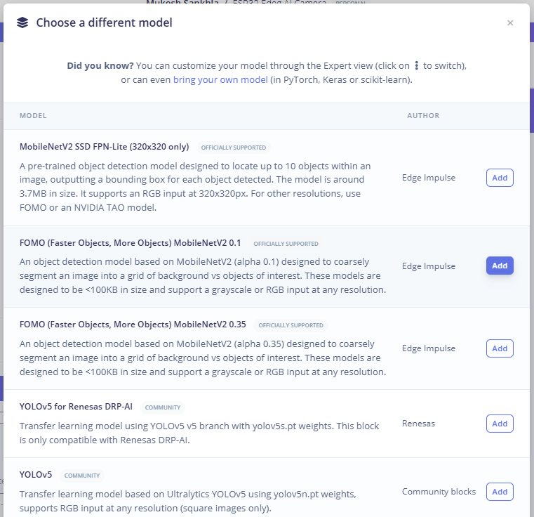
Choose the Model:
*Click on "Choose a different model" and select FOMO (Faster Objects, More Objects) *MobileNetV2 0.35 from the list.
*Confirm your selection.
Train the Model:
*Click "Save & Train" to start the training process.
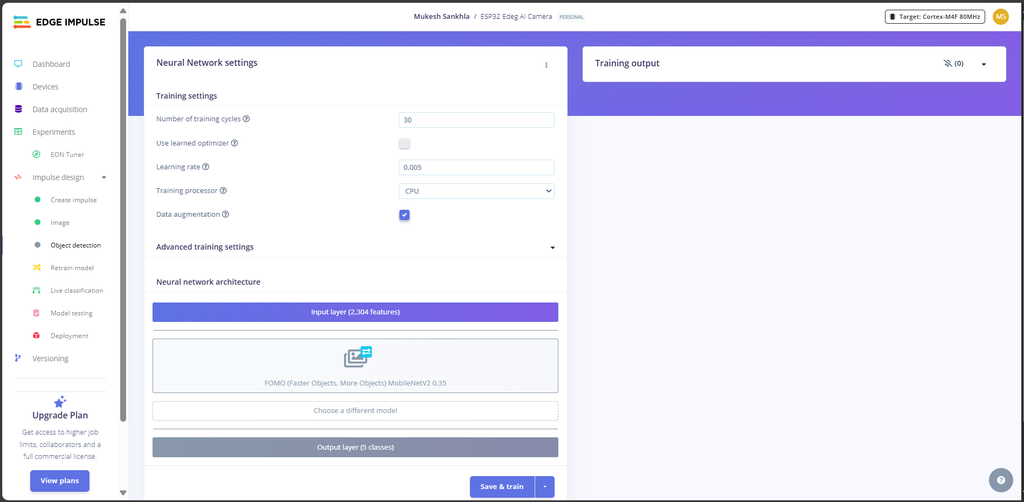
Understanding the Results:
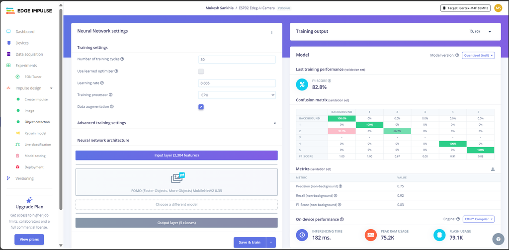
*After training, you will see the following outputs:
*F1 Score: 82.8%
*Indicates the model's accuracy in identifying objects across all classes.
Confusion Matrix:
*This matrix shows the model's performance for each class.
*Green cells represent correct predictions, and red cells indicate misclassifications.
Metrics (Validation Set):
*Precision: 0.75, The accuracy of the positive predictions.
*Recall: 0.92,The ability of the model to find all relevant instances.
*F1 Score: 0.83, A balance between precision and recall.
*The deployment process involves creating an Arduino-compatible library from your trained Edge Impulse model.
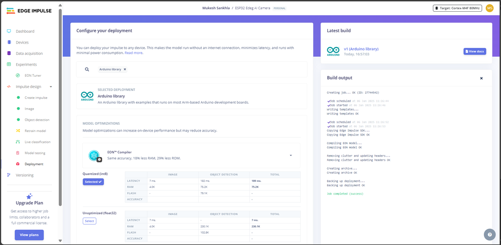
1. Generate the Deployment Files
*Navigate to the Deployment tab in your Edge Impulse project.
*Under the deployment options, select Arduino Library.
*Make sure the Quantized (int8) option is selected (this ensures the model is optimized for the ESP32).
*Click Build to generate the library.
*After the build completes, download the generated .zip file for the Arduino library.
*In Arduino IDE, go to Sketch > Include Library > Add .ZIP Library and select the downloaded zip file.
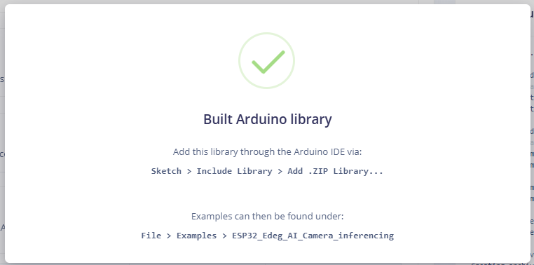
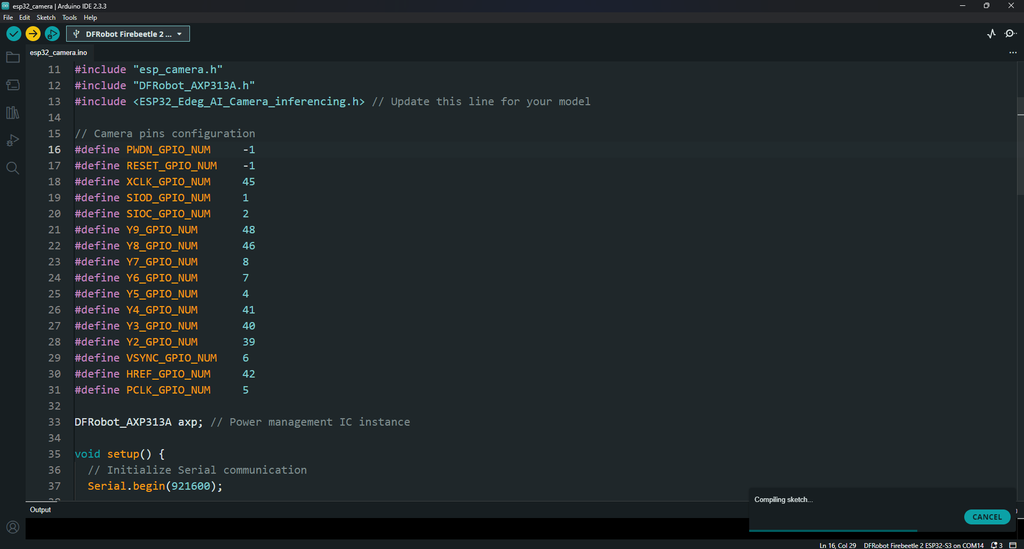 *Copy the provided code and paste it in the Arduino IDE
*Select the correct board (DFRobot FireBeetle 2 ESP32-S3) in the Tools menu of the Arduino IDE.
*Select the correct Port for your device.
*Click Upload to flash the code to your ESP32.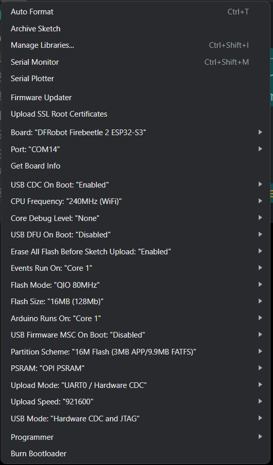
/* Includes ---------------------------------------------------------------- */
#include <ESP32_Edeg_AI_Camera_inferencing.h>
#include "edge-impulse-sdk/dsp/image/image.hpp"
#include "esp_camera.h"
#include "DFRobot_AXP313A.h"

// Camera model definition
#define CAMERA_MODEL_DFRobot_FireBeetle2_ESP32S3

DFRobot_AXP313A axp;

// FireBeetle ESP32S3 Camera GPIO Pins
#define PWDN_GPIO_NUM     -1
#define RESET_GPIO_NUM    -1
#define XCLK_GPIO_NUM     45
#define SIOD_GPIO_NUM     1
#define SIOC_GPIO_NUM     2
#define Y9_GPIO_NUM       48
#define Y8_GPIO_NUM       46
#define Y7_GPIO_NUM       8
#define Y6_GPIO_NUM       7
#define Y5_GPIO_NUM       4
#define Y4_GPIO_NUM       41
#define Y3_GPIO_NUM       40
#define Y2_GPIO_NUM       39
#define VSYNC_GPIO_NUM    6
#define HREF_GPIO_NUM     42
#define PCLK_GPIO_NUM     5

/* Constant defines -------------------------------------------------------- */
#define EI_CAMERA_RAW_FRAME_BUFFER_COLS           320
#define EI_CAMERA_RAW_FRAME_BUFFER_ROWS           240
#define EI_CAMERA_FRAME_BYTE_SIZE                 3

/* Private variables ------------------------------------------------------- */
static bool debug_nn = false; // Set this to true to see e.g. features generated from the raw signal
static bool is_initialised = false;
uint8_t *snapshot_buf; // Points to the output of the capture

static camera_config_t camera_config = {
    .pin_pwdn = PWDN_GPIO_NUM,
    .pin_reset = RESET_GPIO_NUM,
    .pin_xclk = XCLK_GPIO_NUM,
    .pin_sscb_sda = SIOD_GPIO_NUM,
    .pin_sscb_scl = SIOC_GPIO_NUM,

    .pin_d7 = Y9_GPIO_NUM,
    .pin_d6 = Y8_GPIO_NUM,
    .pin_d5 = Y7_GPIO_NUM,
    .pin_d4 = Y6_GPIO_NUM,
    .pin_d3 = Y5_GPIO_NUM,
    .pin_d2 = Y4_GPIO_NUM,
    .pin_d1 = Y3_GPIO_NUM,
    .pin_d0 = Y2_GPIO_NUM,
    .pin_vsync = VSYNC_GPIO_NUM,
    .pin_href = HREF_GPIO_NUM,
    .pin_pclk = PCLK_GPIO_NUM,

    .xclk_freq_hz = 20000000,
    .ledc_timer = LEDC_TIMER_0,
    .ledc_channel = LEDC_CHANNEL_0,

    .pixel_format = PIXFORMAT_GRAYSCALE, // YUV422, GRAYSCALE, RGB565, JPEG
    .frame_size = FRAMESIZE_QVGA,   // QQVGA-UXGA Do not use sizes above QVGA when not JPEG

    .jpeg_quality = 12,             // 0-63 lower number means higher quality
    .fb_count = 1,                  // If more than one, i2s runs in continuous mode. Use only with JPEG
    .fb_location = CAMERA_FB_IN_PSRAM,
    .grab_mode = CAMERA_GRAB_WHEN_EMPTY,
};

/* Function definitions ------------------------------------------------------- */
bool ei_camera_init(void);
void ei_camera_deinit(void);
bool ei_camera_capture(uint32_t img_width, uint32_t img_height, uint8_t *out_buf);

/**
 * @brief      Arduino setup function
 */
void setup() {
    Serial.begin(115200);
    while (!Serial);
    Serial.println("Edge Impulse Inferencing Demo");

    while (axp.begin() != 0) {
      Serial.println("AXP313A initialization failed");
      delay(1000);
    }

    // Enable camera power
    axp.enableCameraPower(axp.eOV2640);

    if (ei_camera_init() == false) {
        ei_printf("Failed to initialize Camera!\r\n");
    } else {
        ei_printf("Camera initialized\r\n");
    }

    ei_printf("\nStarting continuous inference in 2 seconds...\n");
    ei_sleep(2000);
}

/**
 * @brief      Main loop for inferencing
 */
void loop() {
    if (ei_sleep(5) != EI_IMPULSE_OK) {
        return;
    }

    snapshot_buf = (uint8_t *)malloc(EI_CAMERA_RAW_FRAME_BUFFER_COLS * EI_CAMERA_RAW_FRAME_BUFFER_ROWS * EI_CAMERA_FRAME_BYTE_SIZE);

    if (snapshot_buf == nullptr) {
        ei_printf("ERR: Failed to allocate snapshot buffer!\n");
        return;
    }

    ei::signal_t signal;
    signal.total_length = EI_CLASSIFIER_INPUT_WIDTH * EI_CLASSIFIER_INPUT_HEIGHT;
    signal.get_data = &ei_camera_get_data;

    if (ei_camera_capture((size_t)EI_CLASSIFIER_INPUT_WIDTH, (size_t)EI_CLASSIFIER_INPUT_HEIGHT, snapshot_buf) == false) {
        ei_printf("Failed to capture image\r\n");
        free(snapshot_buf);
        return;
    }

    ei_impulse_result_t result = {0};
    EI_IMPULSE_ERROR err = run_classifier(&signal, &result, debug_nn);
    if (err != EI_IMPULSE_OK) {
        ei_printf("ERR: Failed to run classifier (%d)\n", err);
        return;
    }

    ei_printf("Predictions (DSP: %d ms, Classification: %d ms, Anomaly: %d ms): \n",
              result.timing.dsp, result.timing.classification, result.timing.anomaly);

    if (err != EI_IMPULSE_OK) {
      ei_printf("ERR: Failed to run classifier (%d)\n", err);
      free(snapshot_buf);
      return;
    }

    // Check if classification results are valid
    if (EI_CLASSIFIER_LABEL_COUNT > 0 && result.classification != nullptr) {
        for (size_t ix = 0; ix < EI_CLASSIFIER_LABEL_COUNT; ix++) {
            if (result.classification[ix].label != nullptr) { // Check label pointer
                ei_printf("    %s: %.5f\n", result.classification[ix].label, result.classification[ix].value);
            } else {
                ei_printf("    ERR: Null label at index %d\n", ix);
            }
        }
    }

    // Check and print anomaly score if applicable
    if (EI_CLASSIFIER_HAS_ANOMALY == 1) {
        ei_printf("    Anomaly score: %.3f\n", result.anomaly);
    }


    free(snapshot_buf);
}

bool ei_camera_init(void) {
    if (is_initialised) return true;

    esp_err_t err = esp_camera_init(&camera_config);
    if (err != ESP_OK) {
        Serial.printf("Camera init failed with error 0x%x\n", err);
        return false;
    }

    sensor_t *s = esp_camera_sensor_get();
    if (s->id.PID == OV3660_PID) {
        s->set_vflip(s, 1);
        s->set_brightness(s, 1);
        s->set_saturation(s, 0);
    }

    is_initialised = true;
    return true;
}

void ei_camera_deinit(void) {
    esp_camera_deinit();
    is_initialised = false;
}

bool ei_camera_capture(uint32_t img_width, uint32_t img_height, uint8_t *out_buf) {
    if (!is_initialised) {
        ei_printf("ERR: Camera is not initialized\r\n");
        return false;
    }

    camera_fb_t *fb = esp_camera_fb_get();
    if (!fb) {
        ei_printf("Camera capture failed\n");
        return false;
    }

    // Ensure the framebuffer size matches the expected dimensions
    if (fb->width != img_width || fb->height != img_height) {
        ei_printf("ERR: Framebuffer size mismatch. Expected: %lux%lu, Got: %lux%lu\n",
                  (unsigned long)img_width, (unsigned long)img_height,
                  (unsigned long)fb->width, (unsigned long)fb->height);
        esp_camera_fb_return(fb);
        return false;
    }

    // Directly copy grayscale data
    memcpy(out_buf, fb->buf, fb->len);
    esp_camera_fb_return(fb);

    return true;
}

static int ei_camera_get_data(size_t offset, size_t length, float *out_ptr) {
    size_t pixel_ix = offset;
    size_t pixels_left = length;
    size_t out_ptr_ix = 0;

    while (pixels_left != 0) {
        // Convert grayscale byte to a float between 0 and 1
        out_ptr[out_ptr_ix] = snapshot_buf[pixel_ix] / 255.0f;
        out_ptr_ix++;
        pixel_ix++;
        pixels_left--;
    }
    return 0;
}

#if !defined(EI_CLASSIFIER_SENSOR) || EI_CLASSIFIER_SENSOR != EI_CLASSIFIER_SENSOR_CAMERA
#error "Invalid model for current sensor"
#endif
*If you are deploying your own Edge Impulse model, you need to ensure that the correct model is linked in the code.
*Find this line in the code:
#include
*and change it as
#include
Output Should look Like This:
Edge Impulse Inferencing Demo
Camera initialized
Starting continuous inference in 2 seconds...
Predictions (DSP: 45 ms, Classification: 25 ms, Anomaly: 3 ms):
BACKGROUND: 0.95000
1: 0.02000
2: 0.01500
3: 0.00500
4: 0.00500
5: 0.00500
Anomaly score: 0.010
Predictions (DSP: 46 ms, Classification: 26 ms, Anomaly: 3 ms):
BACKGROUND: 0.10000
1: 0.75000
2: 0.13000
3: 0.01000
4: 0.00500
5: 0.00500
Anomaly score: 0.050
Predictions (DSP: 44 ms, Classification: 24 ms, Anomaly: 3 ms):
BACKGROUND: 0.01000
1: 0.01000
2: 0.01000
3: 0.80000
4: 0.08000
5: 0.09000
Anomaly score: 0.020
Conclusion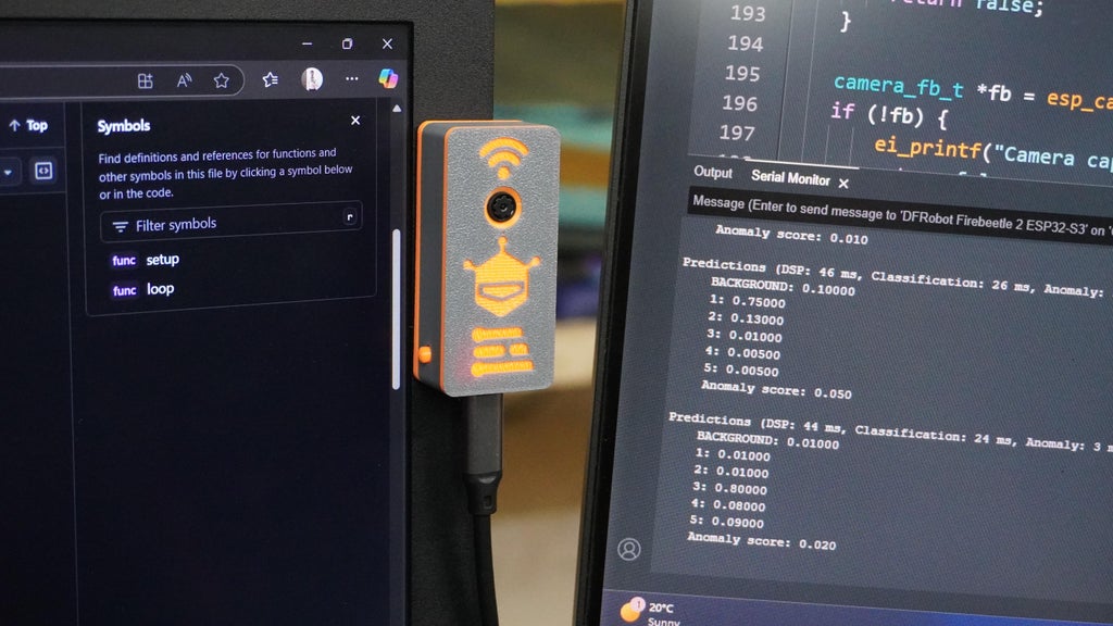
In this article, we walked through the complete process of building an object detection model using Edge Impulse, from setting up the device and collecting data to creating impulses, generating features, and preparing the dataset for training. Each step highlights the simplicity and efficiency of Edge Impulse in enabling developers to build edge AI solutions tailored to their specific applications.
By generating features and visualizing them through the Feature Explorer, we ensured that the data was well-prepared and distinguishable, a critical step in achieving accurate and reliable model performance. Additionally, the platform's metrics for on-device performance, such as processing time and memory usage, make it easier to optimize models for deployment on resource-constrained devices like the ESP32 Edge AI Camera.
A key highlight of this project was the integration of the custom tool you developed, which streamlined specific tasks within the Edge Impulse workflow. This tool significantly enhanced efficiency by automating repetitive processes, improving data preprocessing, and providing deeper insights into the collected data. Its inclusion demonstrates how custom solutions can complement existing platforms to achieve even better results.
Edge Impulse provides a powerful, user-friendly interface that allows anyone, regardless of prior AI experience, to create machine learning models for real-world applications. With the additional support of your custom tool, the workflow becomes even more robust, paving the way for advanced and scalable AI-powered projects.


