How to Make an Automatic Night Light ON/OFF Using LDR and BC547 Transistor | USB Night Light Circuit

In this project, we will learn how to build an automatic night light circuit using an LDR (Light Dependent Resistor) and a BC547 transistor. The circuit is designed to turn ON the LED light in darkness and OFF in daylight automatically. It is powered via a USB power source, making it ideal for use with a power bank or USB adapter.

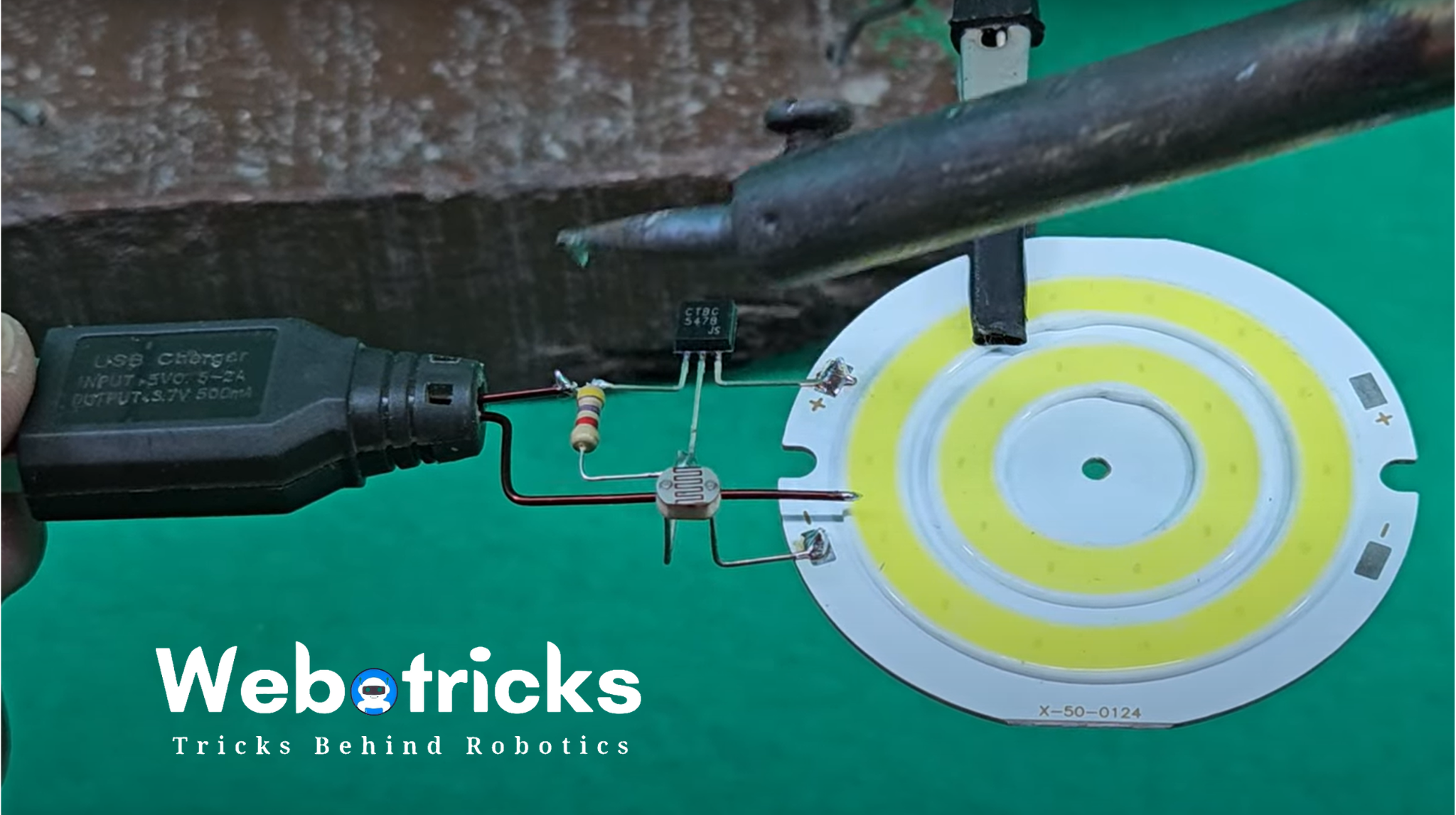
Components Required:
BC547 Transistor
LDR (Light Dependent Resistor) - BUY NOW
4V DC SMD LED Strip
4.7k Resistor
USB Connector
Enameled Copper Wire
Power Bank (or any 5V USB power source)
Working Principle
The circuit uses an LDR to detect ambient light levels. The BC547 transistor acts as a switch, turning the LED strip ON when it gets dark and OFF when there is sufficient light. The resistor helps in adjusting sensitivity.
Step 1: Understanding the Circuit
The circuit works based on the properties of an LDR and a transistor:
The LDR detects the surrounding light intensity.
The BC547 transistor acts as a switch.
When light falls on the LDR, the resistance is low, and the transistor remains OFF, preventing current flow to the LED strip.
In darkness, the LDR's resistance increases, turning ON the transistor and activating the LED strip.
Step 2: Circuit Connections
Wiring the Components
LDR & Resistor:
Connect one terminal of the LDR to the base of the BC547 transistor.
Connect the other terminal of the LDR to 5V (USB Power +ve).
Attach a 4.7kΩ resistor between the base of the transistor and GND (-ve).
Transistor & LED Strip:
Connect the collector of the BC547 transistor to the negative (-ve) terminal of the LED strip.
The emitter of the transistor should be connected to GND (-ve).
The positive (+ve) terminal of the LED strip should go to 5V from the USB source.
Power Source (USB Connector):
+5V USB output → LDR & LED strip (positive terminal).
GND USB output → Emitter of BC547 & Resistor.
Step 3: Assembling the Circuit
Solder the Components: Use enameled copper wire to connect all components securely.
Fix the LDR in an Open Space: Ensure the LDR is positioned where it can detect ambient light properly.
Secure the LED Strip: Attach the SMD LED strip to a stable surface for lighting.
Step 4: Testing the Circuit
Power Up the Circuit using a USB Power Bank or USB Adapter.
Expose the LDR to Light: The LED should turn OFF.
Cover the LDR (simulate darkness): The LED should turn ON.
Adjust the LDR placement if needed to improve sensitivity.
Final Demonstration
The circuit successfully turns the LED strip ON at night and OFF during the day without any manual operation.
This is a simple and cost-effective automatic lighting solution that can be used for night lamps, cabinet lighting, or emergency lighting setups.


