
In this tutorial we will learn how to use LED Indicator Module & HC-SR04 Ultrasonic sensor with Arduino and Visuino.
The closer the obstacles are to the sensor the more LEDs will glow.
Watch the video!


Here we are using a module with 6 LEDs, if you will use a module with more LEDs you might need to connect it to other digital pins or use a breadboard
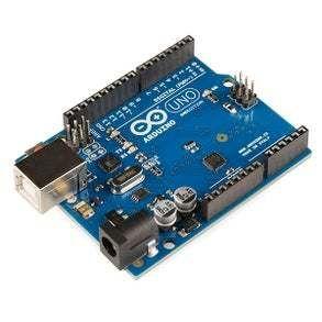
HC-SR04 Ultrasonic sensorArduino UNO or Arduino Mega (or any other board)Visuino program: Download VisuinoJumper wires
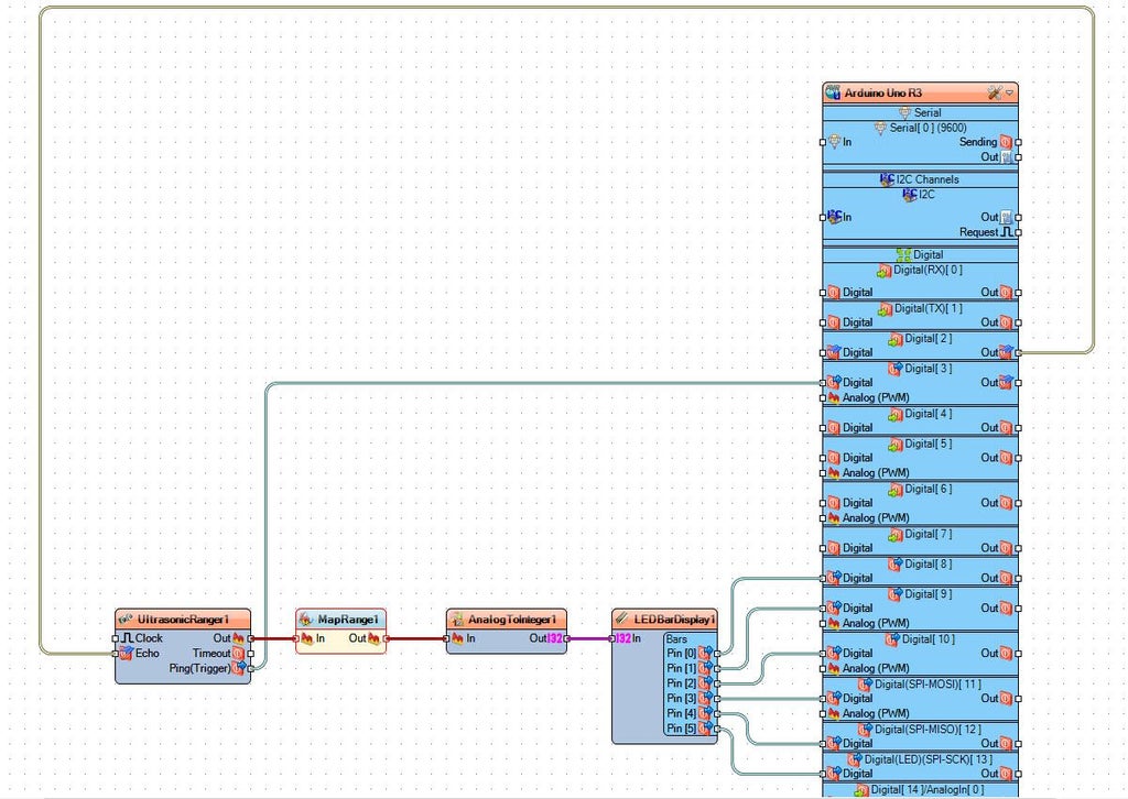
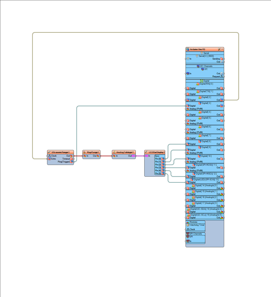
For module with 6 LEDs: Put the module on the Arduino board digital pins [8,9,10,11,12,13,GND]
D6 > digital pin [8]D5 > digital pin [9]D4 > digital pin [10]D3 > digital pin [11]D2 > digital pin [12]D1 > digital pin [13]GND > pin [GND]If you are using a module with more LEDs you might need to use other digital pins or connect it to the breadboard.
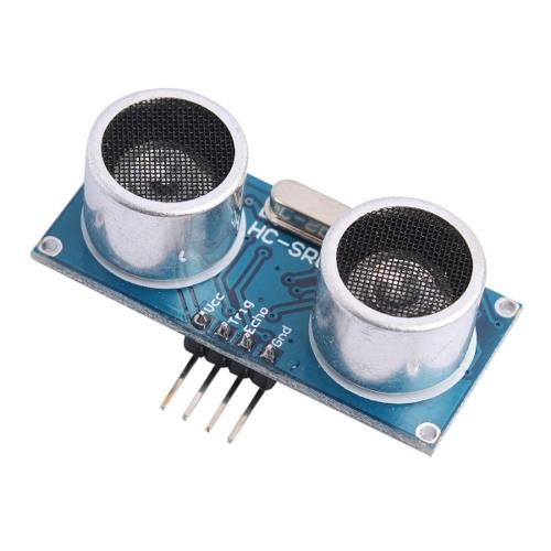
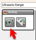
Connect Ultrasonic module pin (VCC) to Arduino pin [+5V]Connect Ultrasonic module pin (GND) to Arduino pin [GND]Connect Ultrasonic module pin (ECHO) to Arduino pin digital (2)Connect Ultrasonic module pin (TRIG) to Arduino pin digital (3)

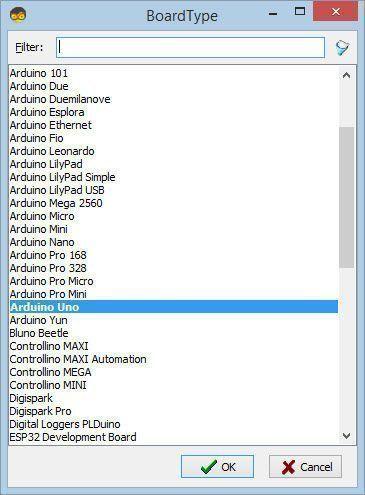
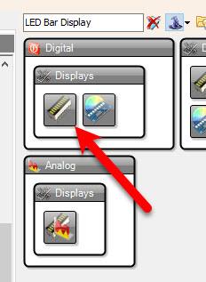
Start Visuino as shown in the first picture Click on the "Tools" button on the Arduino component (Picture 1) in Visuino When the dialog appears, select "Arduino UNO" as shown on Picture 2
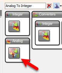
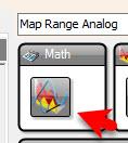
"Map Range Analog" component will transform our distance from the ultrasonic sensor to the number of LEDs
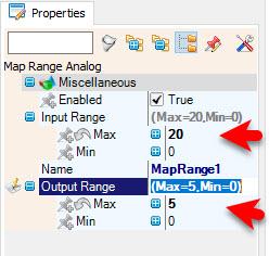
Select "MapRange1" and in the properties window set "Input Range" > "Max" to 20 <
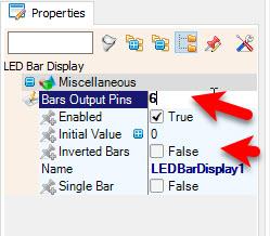
To change the LED direction select "LEDBarDisplay1" and in the properties window set "Inverted Bars" to True
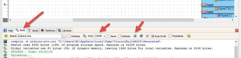
In Visuino, at the bottom click on the "Build" Tab, make sure the correct port is selected, then click on the "Compile/Build and Upload" button.
If you power the Arduino module the LEDs on the indicator module will start to indicate the distance of the obstacle detected by ultrasonic sensor.
Congratulations! You have completed your project with Visuino. Also attached is the Visuino project, that I created for this tutorial, you can download it and open it in Visuino: https://www.visuino.com


