
In this tutorial we will learn how to make a simple weather station using the Raspberry Pi Pico board & Visuino to display Temperature & Humidity values on the Nextion display.
Watch the video!
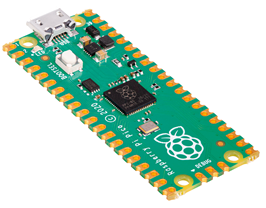
- Raspberry Pi Pico RP2040
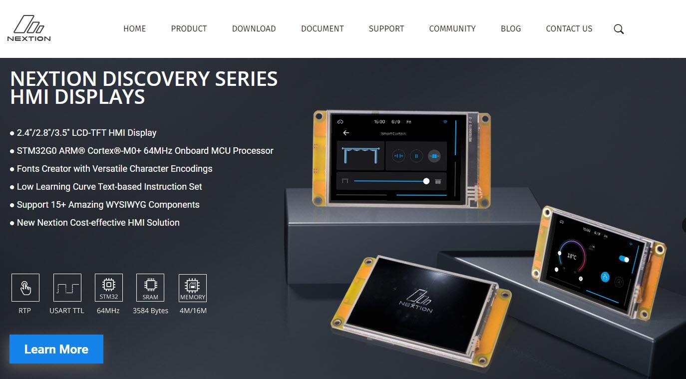
- Nextion Editor: Download Nextion Editor
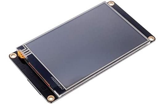
- Nextion Display
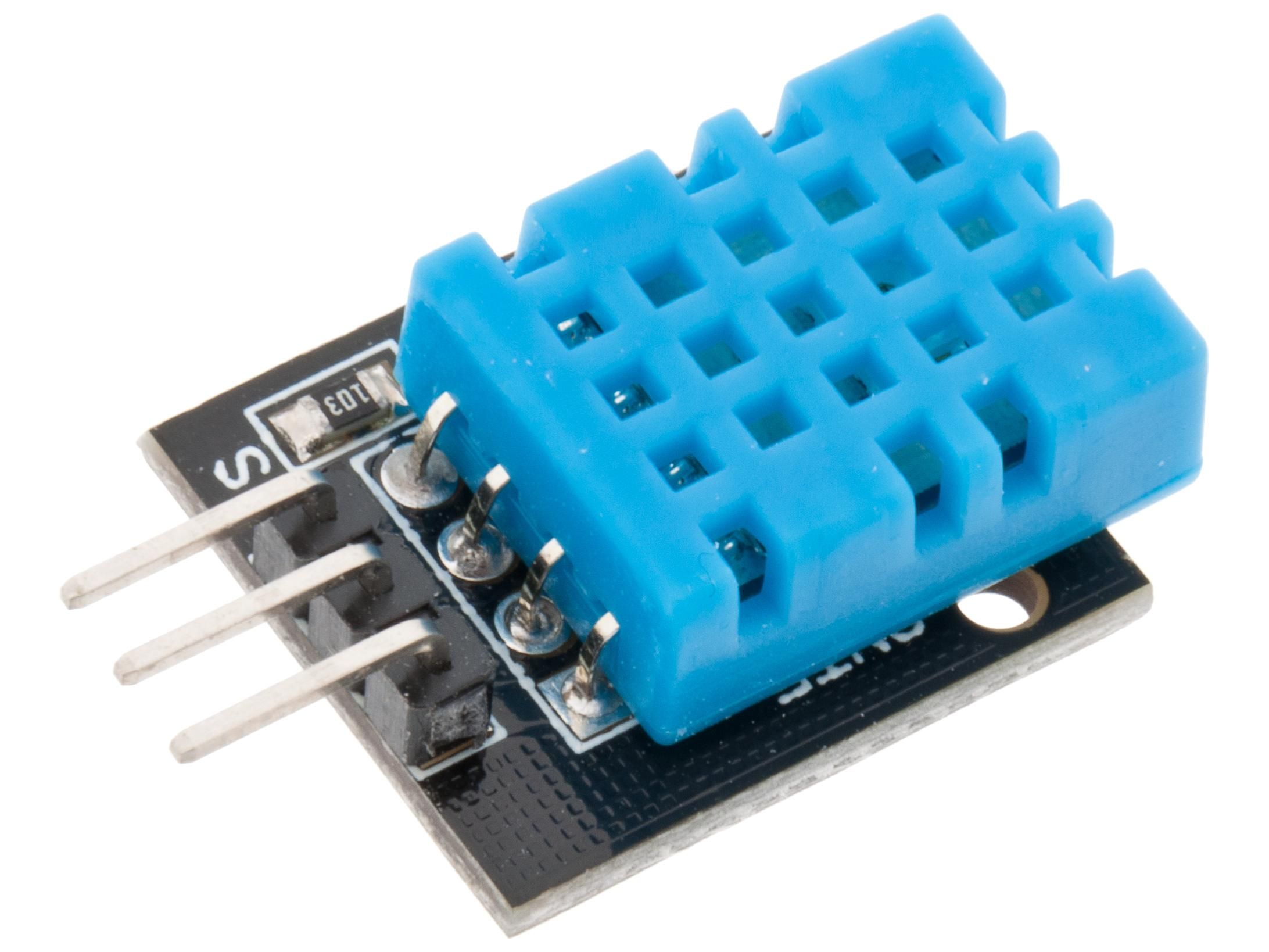
- DHT11 sensor
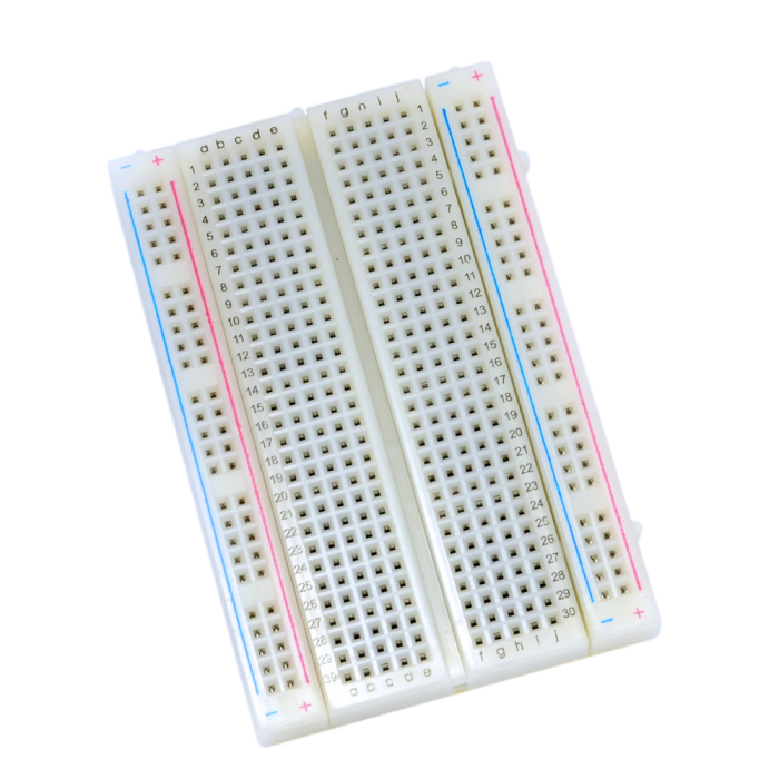
- Breadboard
- Jumper wires
- Visuino program: Download Visuino
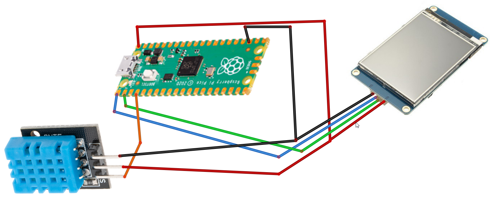
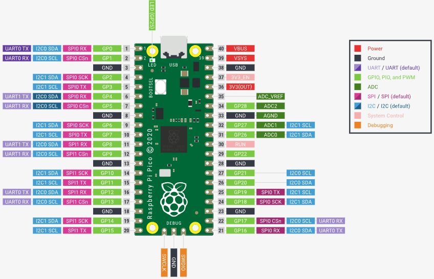
- Connect Nextion Display pin [+5V] to Pi Pico RP2040 pin [VBUS]
- Connect Nextion Display pin [GND] to Pi Pico RP2040 pin [GND]
- Connect Nextion Display pin [RX] to Pi Pico RP2040 pin [1]
- Connect Nextion Display pin [TX] to Pi Pico RP2040 pin [2]
- Connect DHT11 pin [+5V] to Pi Pico RP2040 pin [VBUS]
- Connect DHT11 pin [GND] to Pi Pico RP2040 pin [GND]
- Connect DHT11 pin [S] to Pi Pico RP2040 pin [4]
- Download Nextion Editor and Install it
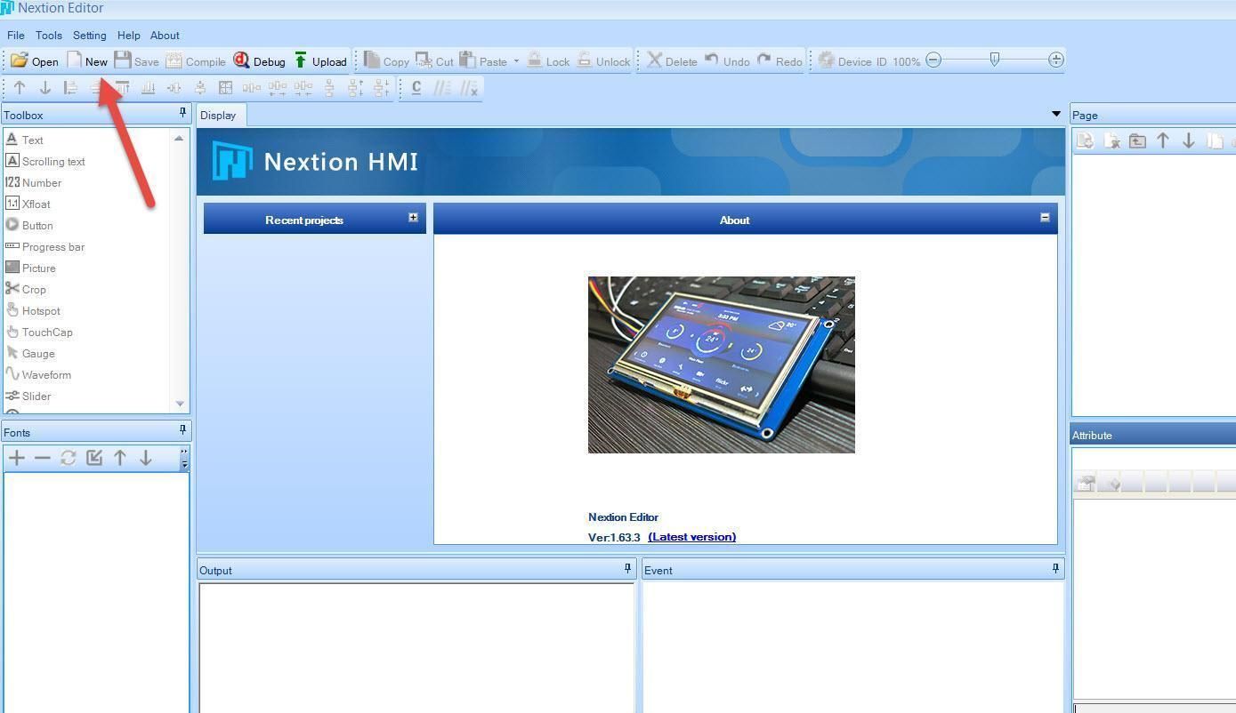
- Start Nextion Editor
- In the Nextion Editor click on the "New" button
- In the Window set the name for the Project like "PicoDht11"
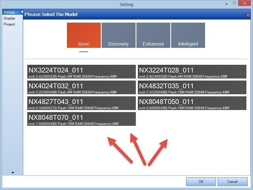
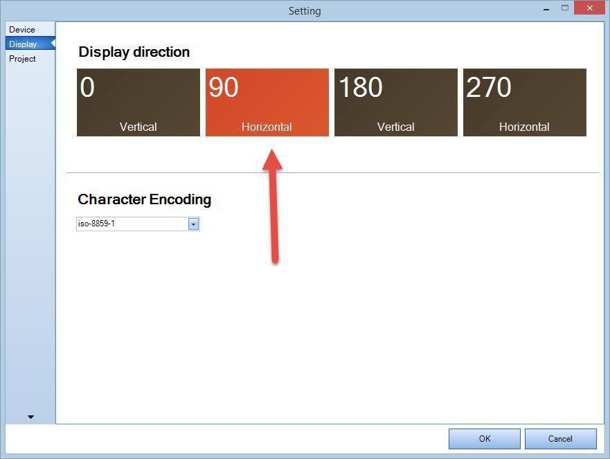
- In the "Setting" window select the Model of your Nextion Display & click "Ok"
- Select Display Direction 90 & click "Ok"
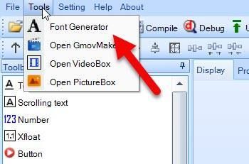
- In the Menu select "Tools">"Font Generator"
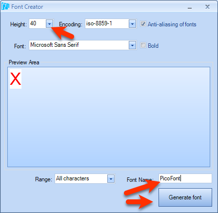
- In the Font creator window set the "Height" to 40 & set the name for your font and click "Generate Font", Save the Font, you will be asked "Add the generated font?" Click Yes
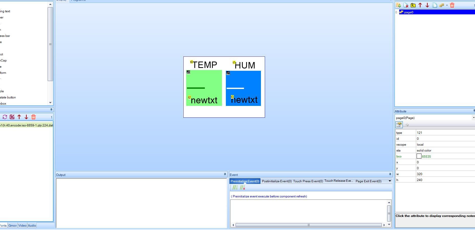
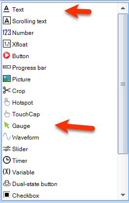
- In the Editor on the left in the "Toolbox" find:
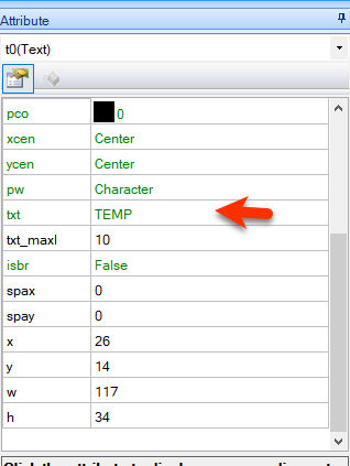
- "Text" & drag it to the right
- and in the Attribute window set "txt" to TEMP
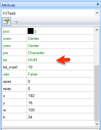
- drag another "Text" to the right
- and in the Attribute window set "txt" to HUM
- In the Editor on the left in the "Toolbox" find:
- "Gauge" & drag it to the right
- and in the Attribute window set "bco" to green
- drag another "Gauge" to the right
- and in the Attribute window set "bco" to blue
- You can also set other settings such as "PCO" or "WID"
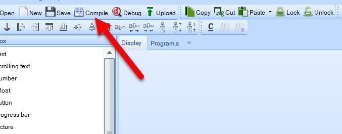
- In the Toolbar click on the "Compile" button
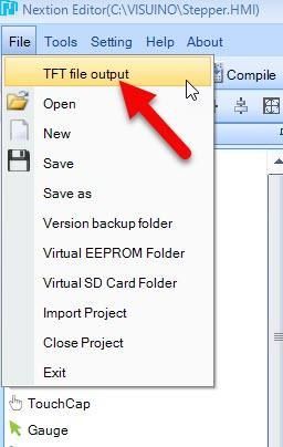
- In the Menu Select "File" > "TFT File Output"
- Set the Output folder & click on the "Output" button
- Save the File to the SD card
- Insert the SD card to your Nextion Display
- Power the Raspberry Pi Pico/RP2040 and you will notice that the Nextion Display will start to Update it self
- On the Finish disconnect the power and remove the SD card from the Nextion display
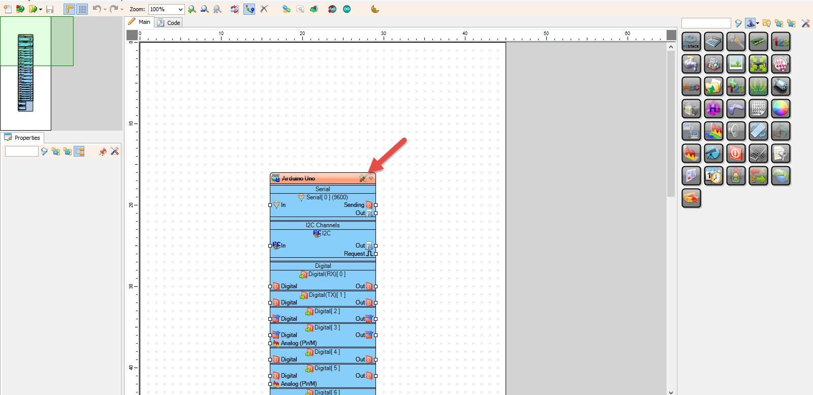
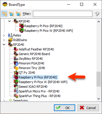
Start Visuino as shown in the first picture Click on the "Tools" button on the Arduino component (Picture 1) in Visuino When the dialog appears, select "Raspberry Pi Pico (RP2040)" as shown on Picture 2
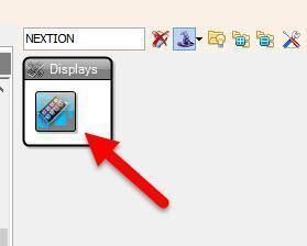
- Add "Nextion Display" component
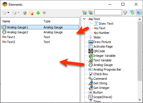
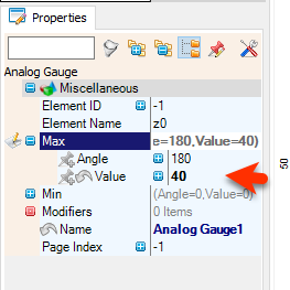
- Double click on the "DisplayNextion1" And in the Elements window drag "Analog Gauge" to the left side and in the properties window set "Max" > "Value" to 40
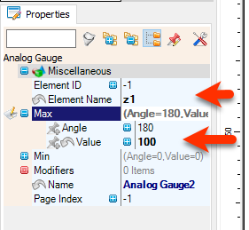
- Drag another ""Analog Gauge" to the left side and in the properties window set "Max" > "Value" to 100 and "Element Name" to z1
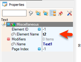
- Drag "Text" element to the left side and in the properties window set "Element Name" to t2
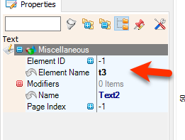
- Drag another "Text" element to the left side and in the properties window set "Element Name" to t3
- Close the Elements window
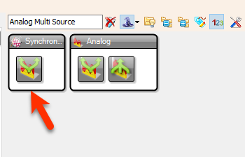
- Add 2X "Analog Multi Source" component
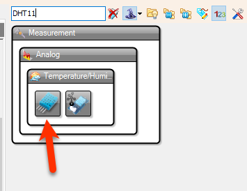
- Add "DHT11" component
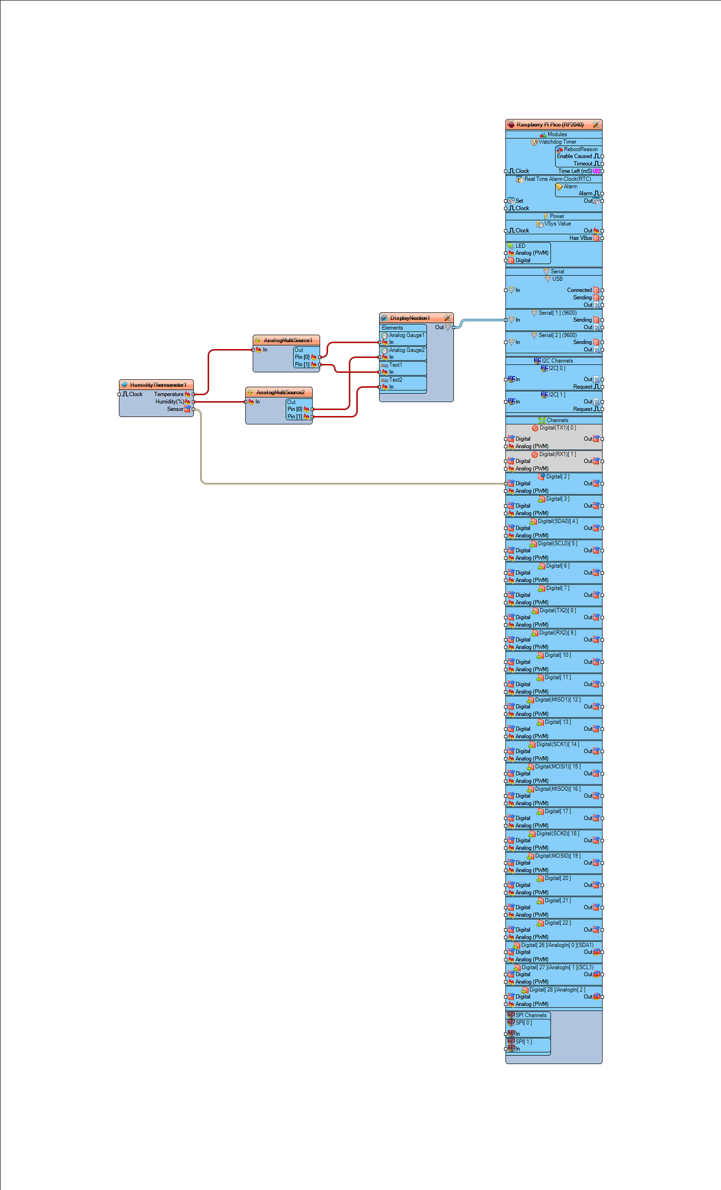
- Connect "HumidityThermometer1" pin [Sensor] to Raspberry Pi Pico/RP2040 digital pin [2]
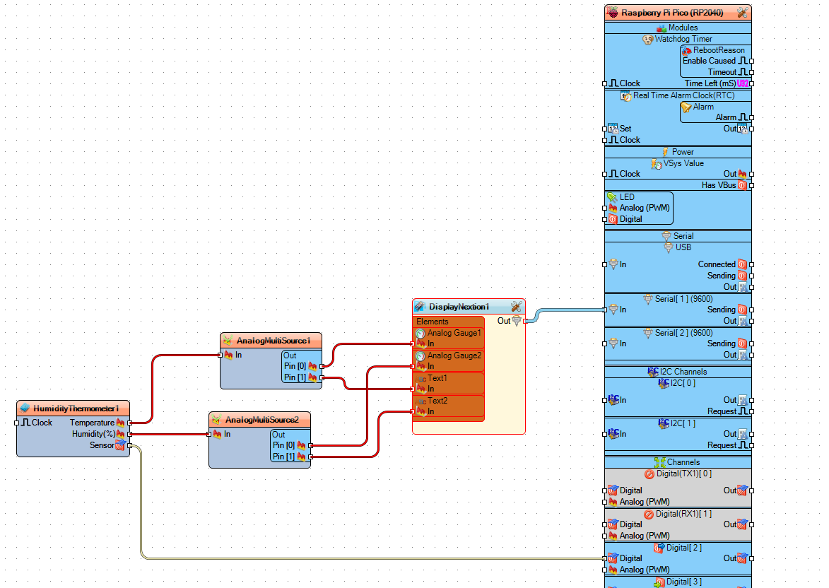
- Connect "HumidityThermometer1" pin [Temperature] to "AnalogMultiSource1" pin [In]
- Connect "HumidityThermometer1" pin [Humidity] to "AnalogMultiSource2" pin [In]
- Connect "AnalogMultiSource1" pin [0] to "DisplayNextion1" > "Analog Gauge1" pin [In]
- Connect "AnalogMultiSource1" pin [1] to "DisplayNextion1" > "Text1" pin [In]
- Connect "AnalogMultiSource2" pin [0] to "DisplayNextion1" > "Analog Gauge2" pin [In]
- Connect "AnalogMultiSource2" pin [1] to "DisplayNextion1" > "Text2" pin [In]
- Connect "DisplayNextion1" pin [Out] to Raspberry Pi Pico/RP2040 serial 1 pin [In]
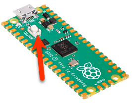
- Before uploading the Project hold the button "BOOTSEL" on the board while connecting it to the USB on your computer.
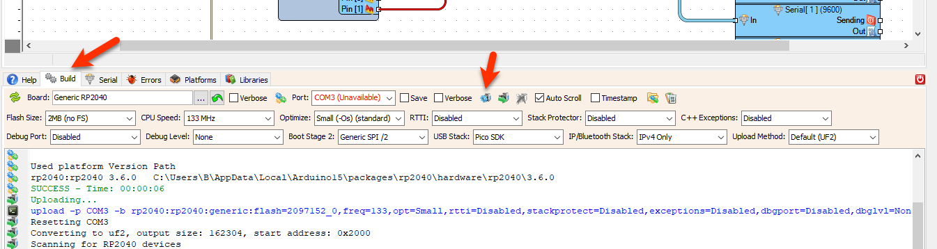
- After connecting it to the USB, release the button and in Visuino click on the button Compile/Build and Upload.
- You don't need to select any port or anything else, Visuino will do all the work and Upload the project.
After uploading the project to the Raspberry Pi Pico/RP2040 the Nextion display will start to show the Temperature and Humidity values.
Congratulations! You have completed your Weather Station project with Visuino. Also attached is the Visuino project, that I created for this Tutorial. You can download and open it in Visuino: https://www.visuino.com
For more Pico ideas &Troubleshooting, check this tutorial:
https://www.instructables.com/RP2040-Raspberry-Pi-Pico-LED-Blink-Using-Visuino/


