
In this simple tutorial we will learn how to control 2 stepper motors using a rotary encoder sensor & Arduino.
Watch the Video!
- Arduino UNO (or any other board)
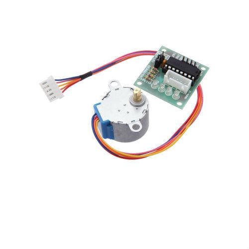
- 2X Stepper motor 28byj-48 & stepper motor driver board
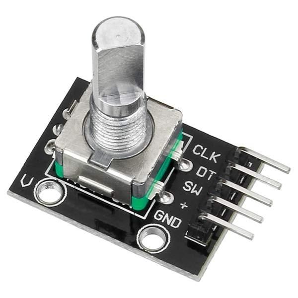
- Rotary Encoder Sensor
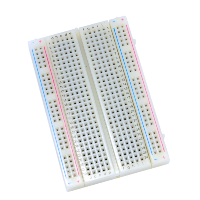
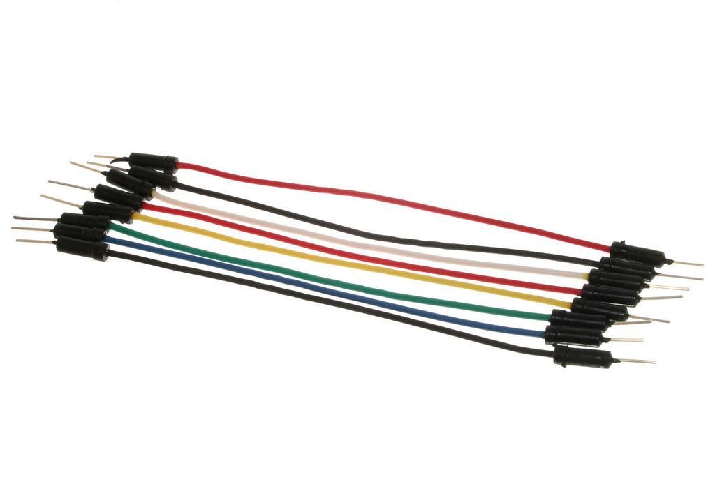
- Jumper wires
- Visuino program: Download Visuino
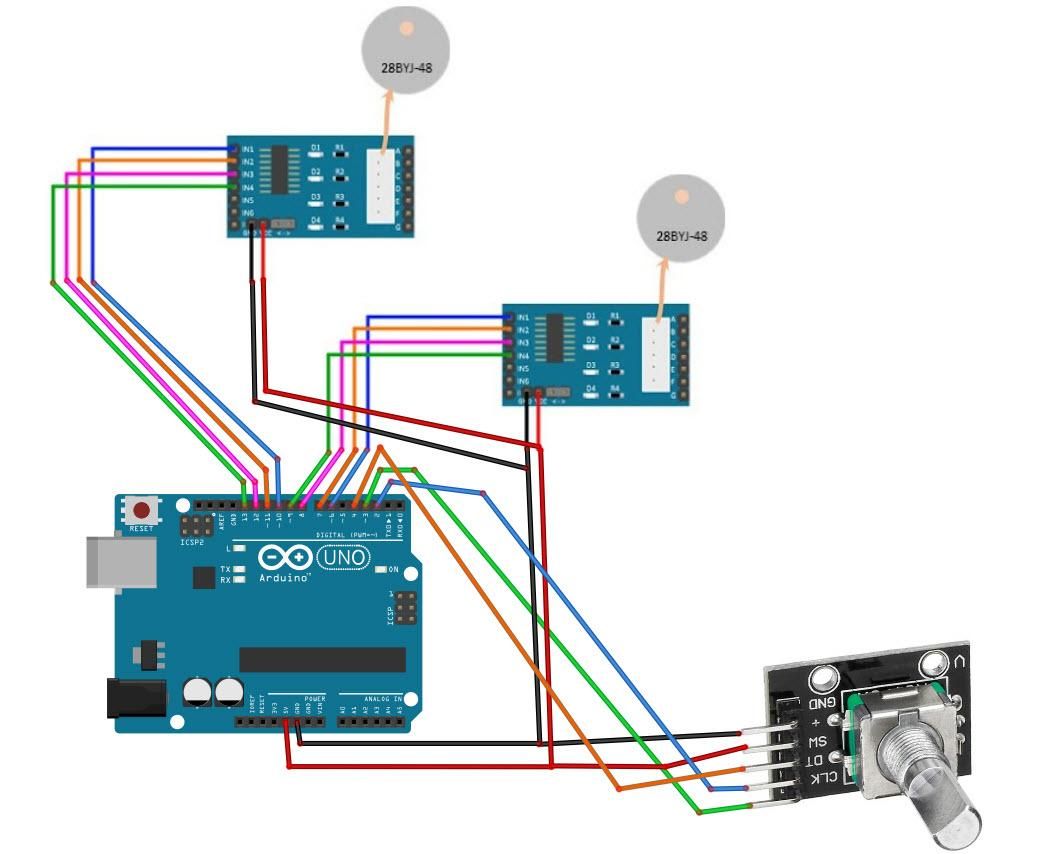
- Connect Arduino pin [5V] to Driver Board1 pin [VCC]
- Connect Arduino pin [GND] to Driver Board1 1pin [GND]
- Connect Arduino digital pin [6] to Driver Board1 pin [IN1]
- Connect Arduino digital pin [7] to Driver Board1 pin [IN2]
- Connect Arduino digital pin [8] to Driver Board1 pin [IN3]
- Connect Arduino digital pin [9] to Driver Board1 pin [IN4]
- Connect Arduino pin [5V] to Driver Board2 pin [VCC]
- Connect Arduino pin [GND] to Driver Board2 1pin [GND]
- Connect Arduino digital pin [10] to Driver Board2 pin [IN1]
- Connect Arduino digital pin [11] to Driver Board2 pin [IN2]
- Connect Arduino digital pin [12] to Driver Board2 pin [IN3]
- Connect Arduino digital pin [13] to Driver Board2 pin [IN4]
Connecting Encoder module:
- Connect Encoder module pin [CLK] to Arduino digital pin [2]
- Connect Encoder module pin [DT] to Arduino digital pin [3]
- Connect Encoder module pin [SW] to Arduino digital pin [4]
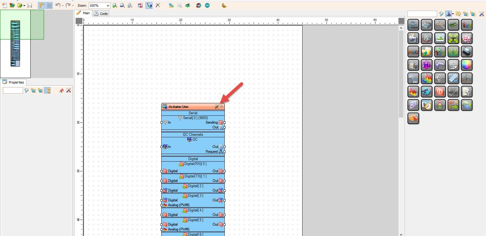
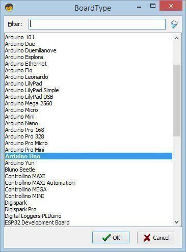
Start Visuino as shown in the first picture Click on the "Tools" button on the Arduino component (Picture 1) in Visuino When the dialog appears, select "Arduino UNO" as shown on Picture 2
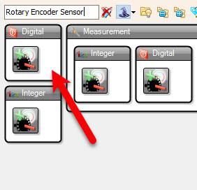
- Add "Rotary Encoder Sensor" component
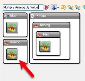
- Add "Multiply Analog By Value" component
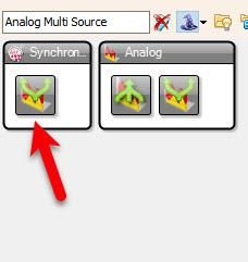
- Add "Analog Multi Source" component
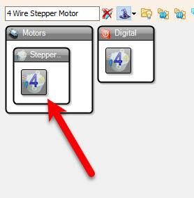
- Add 2X "4 Wire Stepper Motor" component
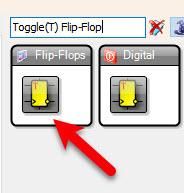
- Add "Toggle(T) Flip-Flop" component
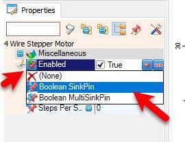
- Select "Stepper1" and in the properties window select "Enabled" click on the pin icon and select "Boolean SinkPin"
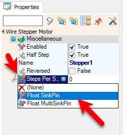
- Select "Stepper1" and in the properties window select "Steps Per Second" click on the pin icon and select "Float SinkPin"
- Select "Stepper2" and in the properties window select "Enabled" click on the pin icon and select "Boolean SinkPin"
- Select "Stepper2" and in the properties window select "Steps Per Second" click on the pin icon and select "Float SinkPin"
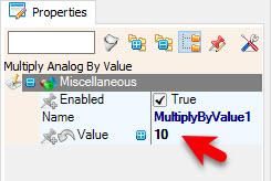
- Select "MultiplyByValue1" and in the properties window set "Value" to 10
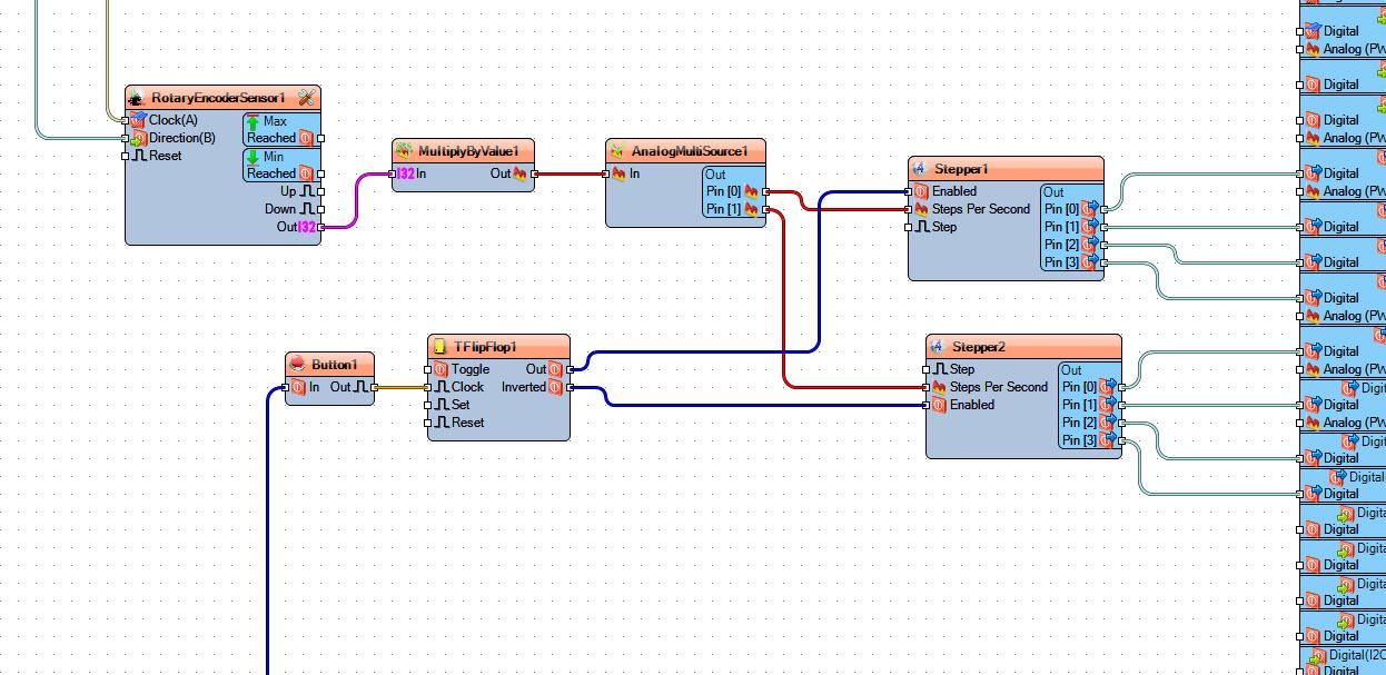
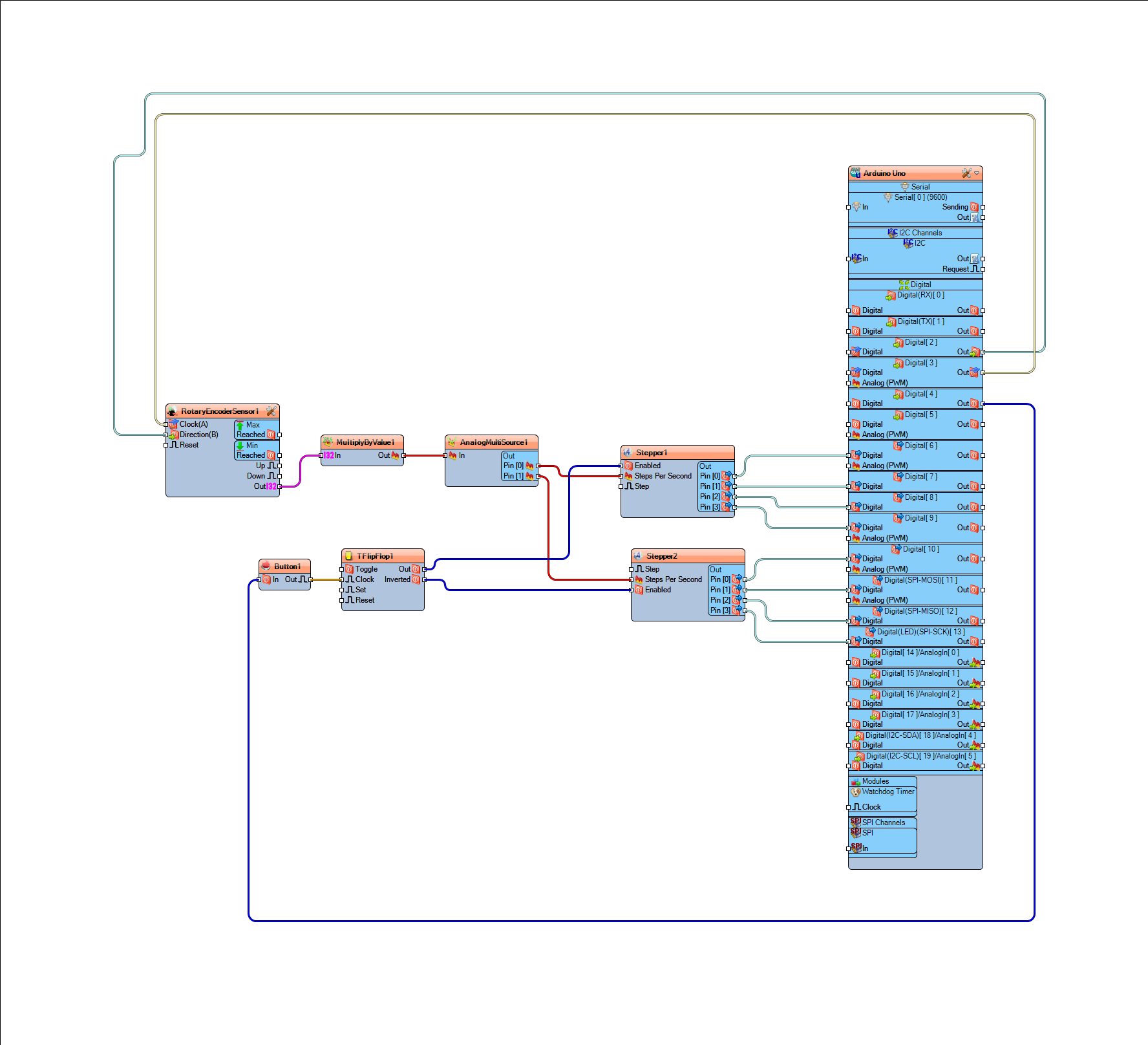
- Connect Arduino digital pin [2] to "RotaryEncoderSensor1" pin [Direction]
- Connect Arduino digital pin [3] to "RotaryEncoderSensor1" pin [Clock]
- Connect "RotaryEncoderSensor1" pin [Out] to "MultiplyByValue1" pin [In]
- Connect "MultiplyByValue1" pin [Out] to "AnalogMultiSource1" pin [In]
- Connect "AnalogMultiSource1" pin [0] to "Stepper1" pin [Steps Per Second]
- Connect "AnalogMultiSource1" pin [1] to "Stepper2" pin [Steps Per Second]
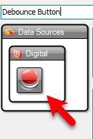
- Connect Arduino digital pin [4] to "Button1" pin [In]
- Connect "Button1" pin [Out] to "TFlipFlop1" pin [Clock]
- Connect "TFlipFlop1" pin [Out] to "Stepper1" digital pin [Enabled]
- Connect "TFlipFlop1" pin [Inverted] to "Stepper1" digital pin [Enabled]
- Connect "Stepper1" pin [0] to Arduino digital pin [6]
- Connect "Stepper1" pin [1] to Arduino digital pin [7]
- Connect "Stepper1" pin [2] to Arduino digital pin [8]
- Connect "Stepper1" pin [3] to Arduino digital pin [9]
- Connect "Stepper2" pin [0] to Arduino digital pin [10]
- Connect "Stepper2" pin [1] to Arduino digital pin [11]
- Connect "Stepper2" pin [2] to Arduino digital pin [12]
- Connect "Stepper2" pin [3] to Arduino digital pin [13]
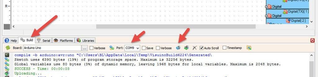
In Visuino, at the bottom click on the "Build" Tab, make sure the correct port is selected, then click on the "Compile/Build and Upload" button.
If you power the Arduino module and rotate the rotary encoder sensor the Stepper Motor will start to rotate in forward direction or reversed direction and if you press the button on the rotary encoder sensor the second motor will start to rotate.
Congratulations! You have completed your project with Visuino. Also attached is the Visuino project, that I created for this Project, you can download it here and open it in Visuino: https://www.visuino.eu


