

Most macropads today rely on custom PCBs and fixed firmware, which makes them difficult to modify, repair, or customize. For this project, I wanted to build something more accessible, modular, and maker-friendly while still looking and feeling like a polished commercial product.
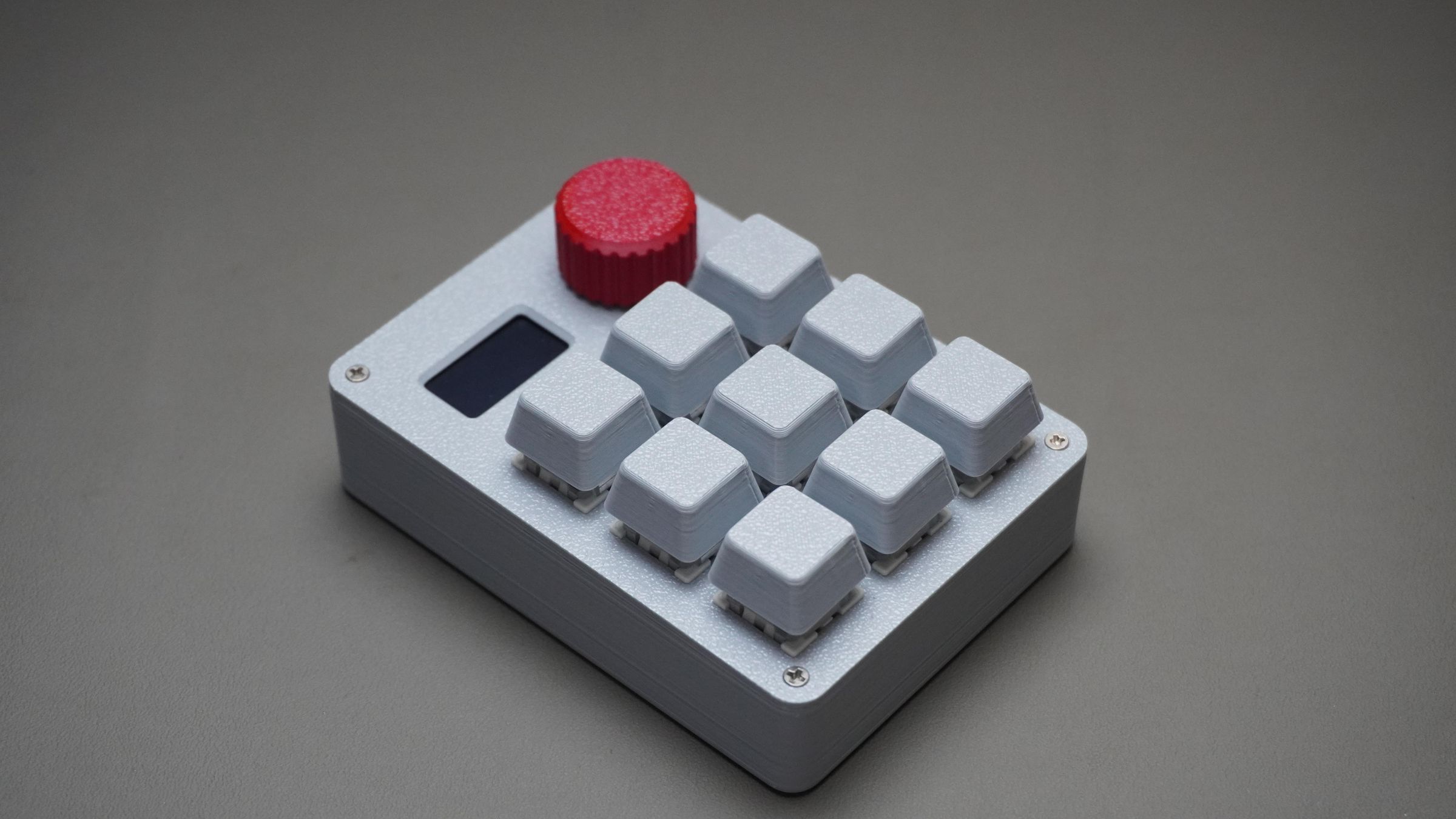
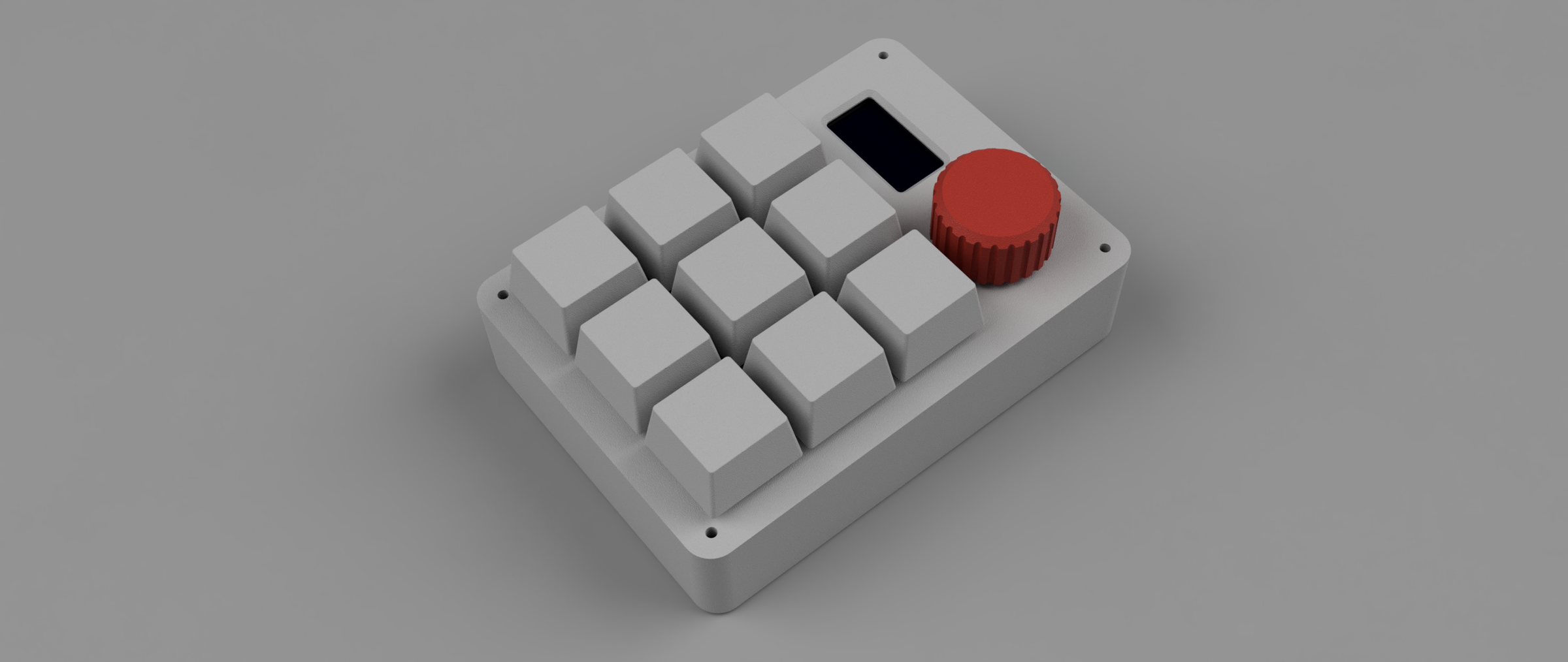
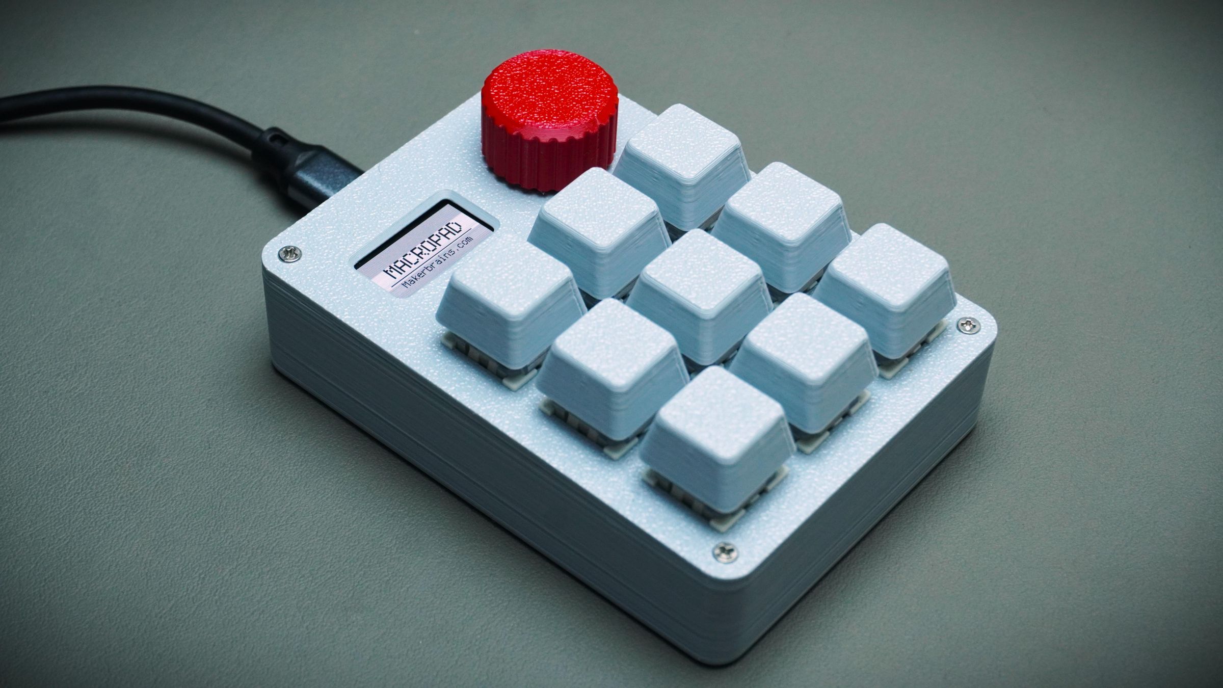
So I designed and built a fully customizable 3D printed macropad using a DFRobot Beetle RP2350, a rotary encoder, a 0.96" OLED display, and 9 mechanical switches — all without using a custom PCB.
The entire macropad was designed in Fusion 360 and assembled using hand-wired connections and snap-fit 3D printed parts. The switches directly lock into the printed frame, making the build simple, repairable, and easy to modify.
The macropad supports multiple workflow modes such as:
- Windows
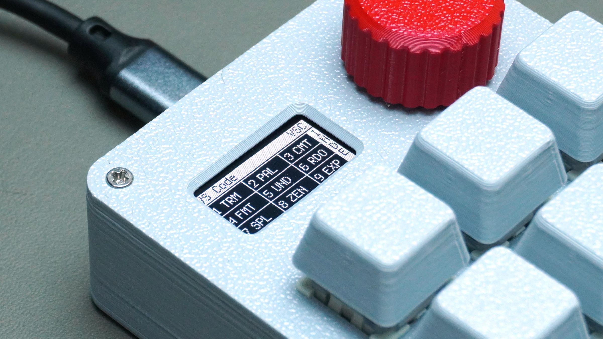
- VS Code
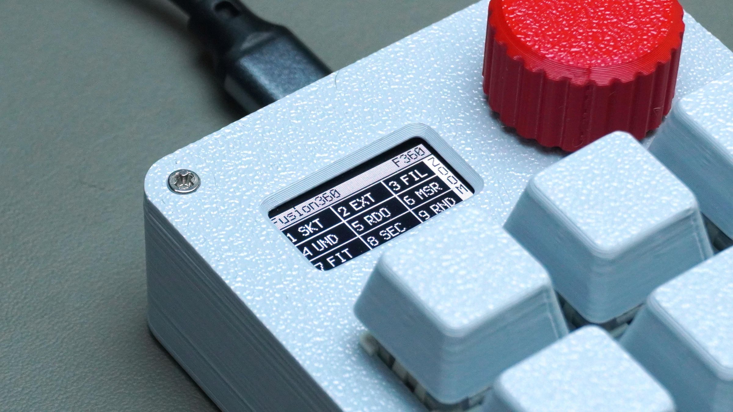
- Fusion 360
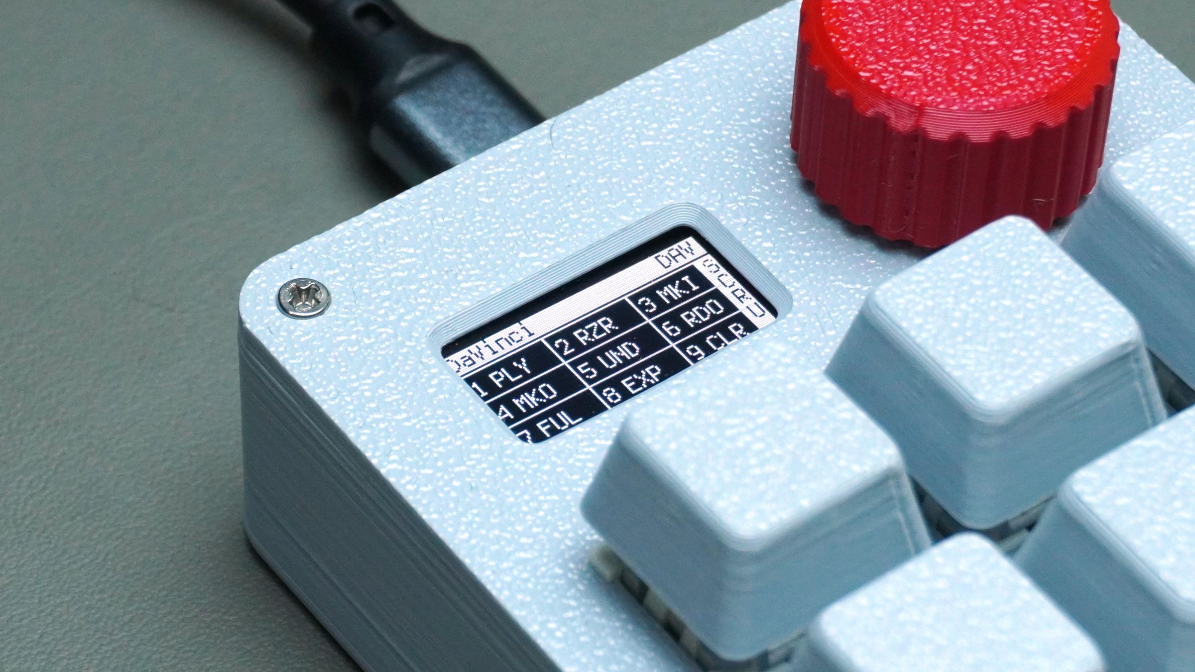
- DaVinci Resolve
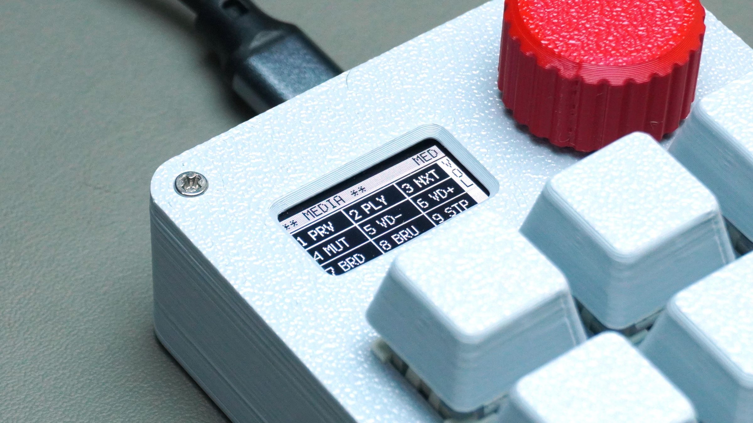
- Media Controls
Using the rotary encoder, you can quickly switch between modes, while the OLED display dynamically updates all key mappings in real time.

To make customization even easier, I also started developing a dedicated web-based configuration tool that allows users to visually manage modes, remap keys, configure encoder actions, and sync everything directly to the device over USB without editing firmware manually.
This project reflects my idea of a better maker ecosystem:
- Hardware that is repairable
- Tools that are customizable
- Devices that are easier to build and learn from
- Open workflows that encourage creativity instead of locked ecosystems
Instead of creating another closed gadget, this project focuses on accessibility, learning, personalization, and long-term usability.

Supplies
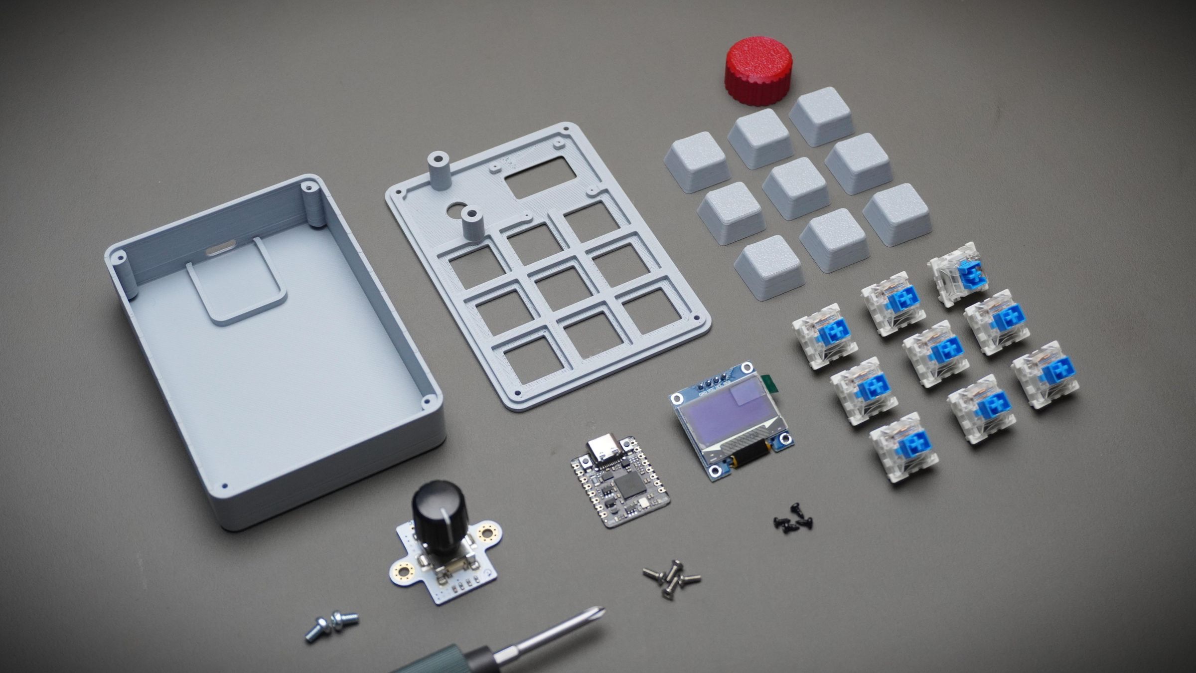
For this build, I used mostly off-the-shelf components combined with fully 3D printed structural parts.
Electronics
Hardware
- M2 and M3 Screws Kit
- Hook-up Wire
- Solder Kit
Fabrication
- 3D Printed Parts
- Access to a 3D Printer
Software
This project was intentionally designed without a custom PCB. All components snap into the 3D printed structure and are directly wired together, making the build easier to modify, repair, and reproduce.
Step 1: Selecting Mechanical Switches
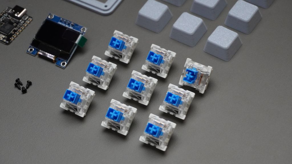
One of the best parts of building a custom macropad is choosing the typing feel you want. Mechanical switches can completely change how the device feels during daily use.
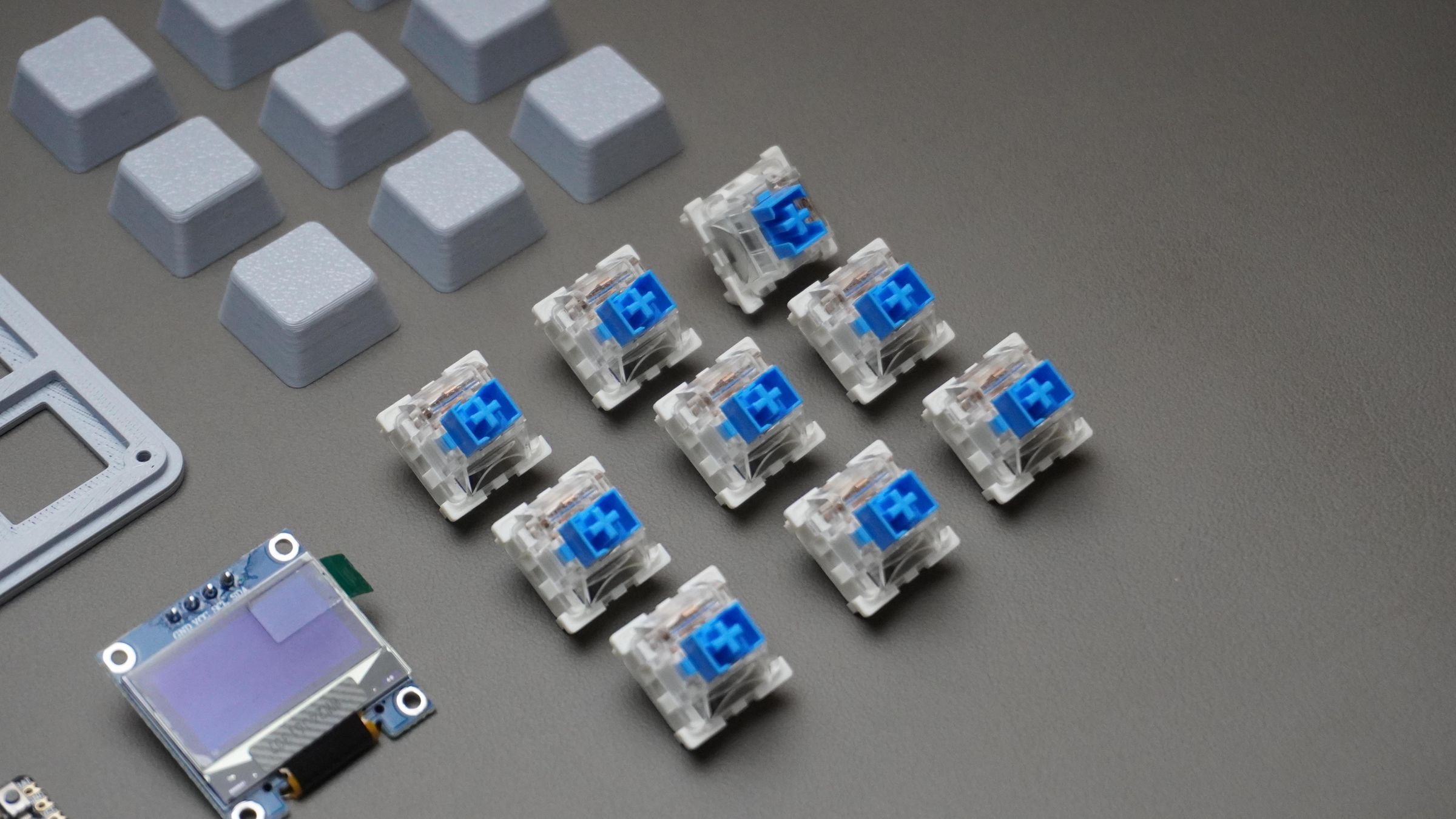
For this build, I used Outemu Blue mechanical switches because I wanted strong tactile feedback while triggering macros. The click and bump make it very satisfying to use, especially for shortcuts and repetitive actions.
I also tested Outemu Red switches, which feel much smoother and quieter since they don’t have a tactile bump or audible click.
If you're building your own version of this macropad, here’s a quick guide to common switch types:
Blue Switches — Clicky & Tactile
Blue switches are:
- Clicky
- Tactile
- Loud
- Very satisfying for shortcuts and macros
You can physically feel and hear the activation point, which makes them great for:
- CAD shortcuts
- Editing workflows
- Productivity tools
- Users who like strong feedback
This is the switch type I used in my macropad because each keypress feels intentional and responsive.
Best for: tactile feedback and satisfying clicks.
Red Switches — Smooth & Linear
Red switches are:
- Linear
- Smooth
- Quiet
- Lightweight
There’s no tactile bump or click sound — the key simply moves straight down smoothly.
These are excellent for:
- Fast repeated inputs
- Silent setups
- Long editing sessions
- Gaming
I have a few red switches as well, and they feel much softer and smoother compared to the Blue switches.
Best for: smooth and quiet operation.
Brown Switches — Balanced Option
Brown switches sit between Blue and Red switches.
They provide:
- Mild tactile feedback
- Minimal noise
- Balanced feel
If you want feedback without loud clicking, Browns are usually the safest choice.
Best for: mixed productivity and everyday use.
Black Switches — Heavier Linear Feel
Black switches are similar to Reds but require more force to press.
They are:
- Linear
- Smooth
- Heavier to actuate
Some users prefer them for avoiding accidental key presses.
Best for: users who prefer firm key presses.
My Recommendation
For a macropad specifically, I personally prefer Blue switches because:
- Every macro press feels deliberate
- The tactile bump helps avoid accidental triggers
- The clicking sound makes the device feel more interactive
But if you want a quieter setup for office or studio use, Red or Brown switches may be a better choice.
Step 2: Meet the Brain of the Macropad - Beetle RP2350
For this project, I wanted a microcontroller board that was:
- Extremely compact
- Powerful enough for multiple macro layers
- Easy to program
- Affordable
- Simple to integrate without designing a PCB
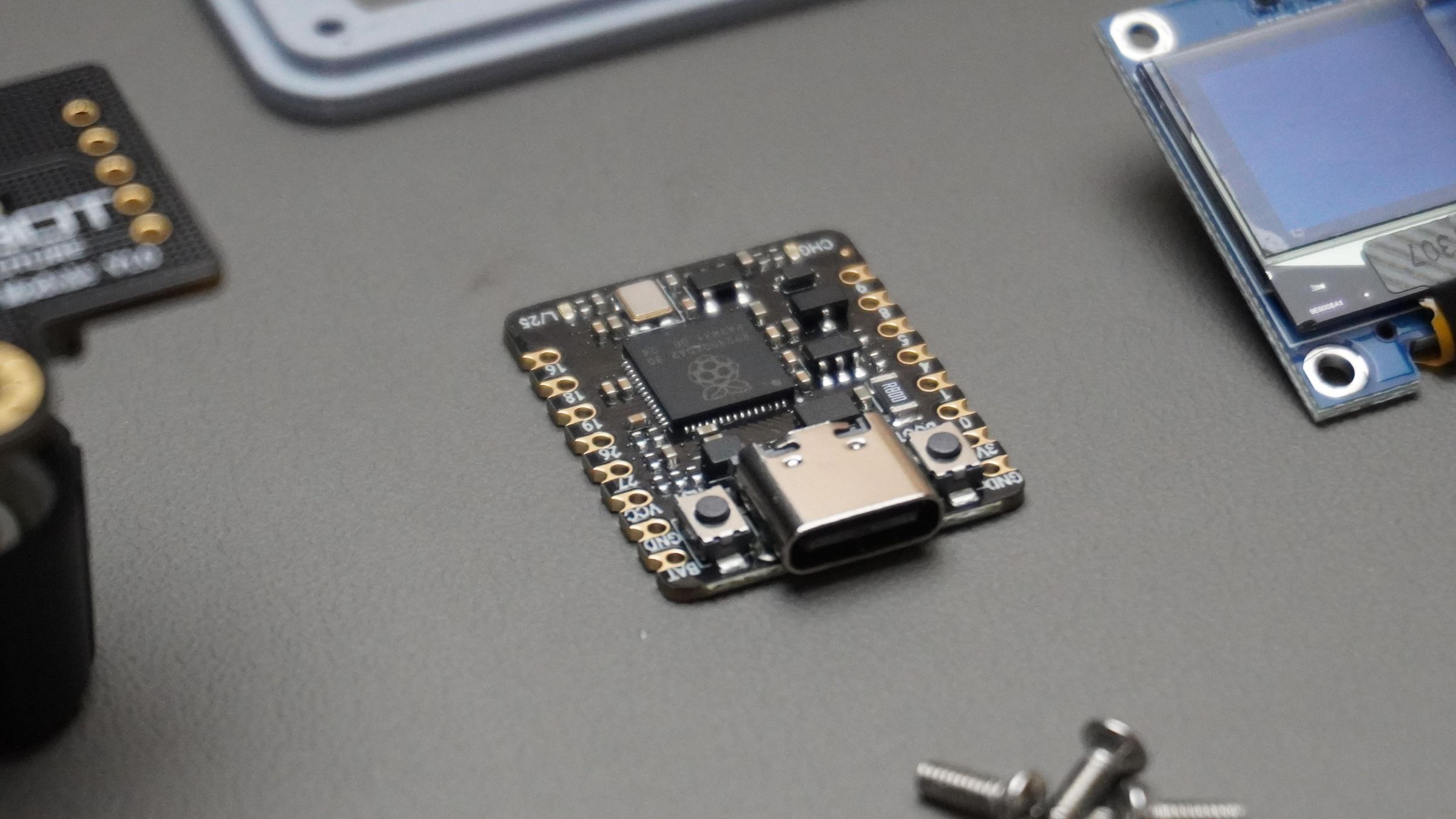
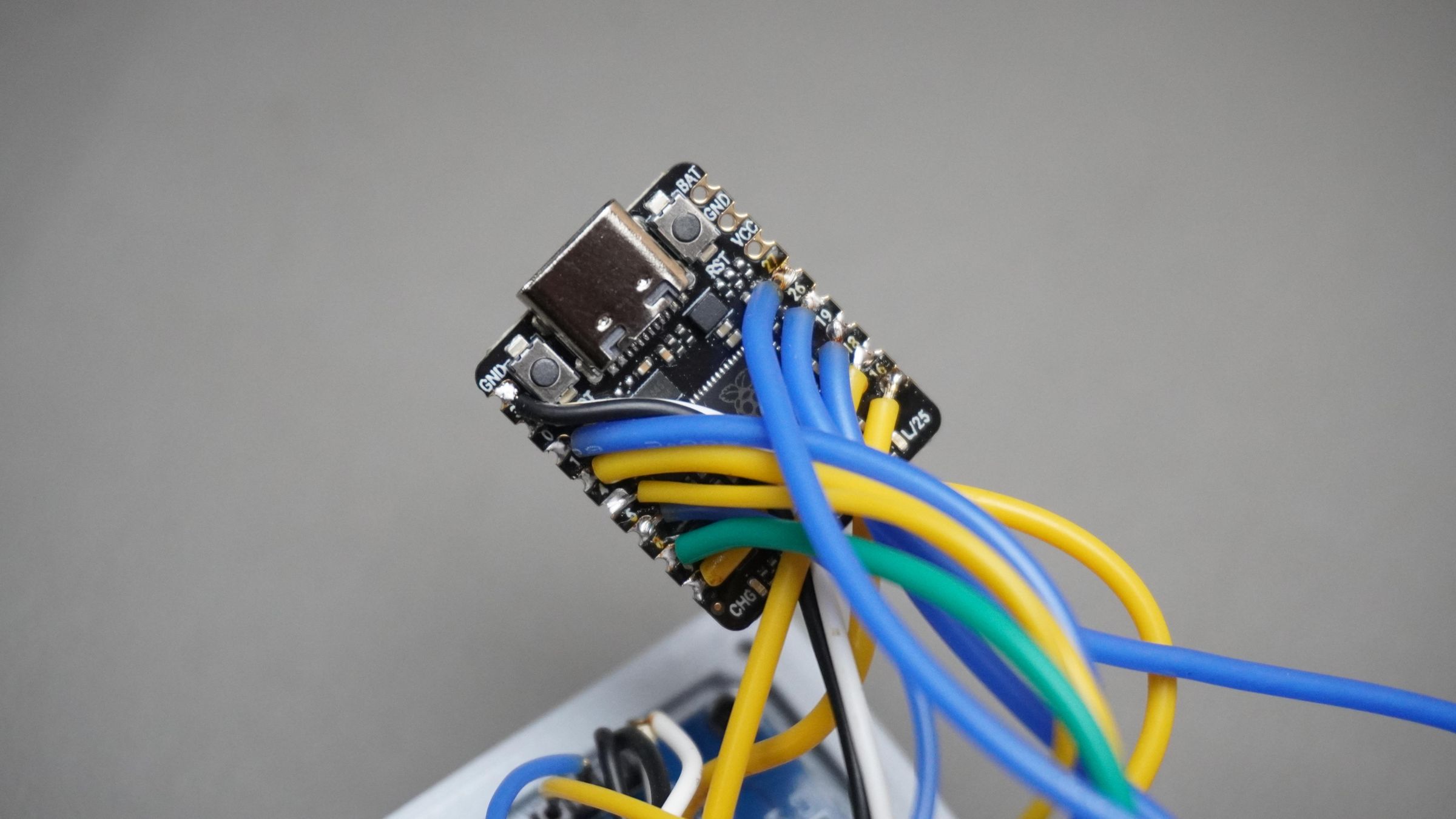
That made the DFRobot Beetle RP2350 the perfect choice.
The Beetle RP2350 is a coin-sized development board based on the Raspberry Pi RP2350 microcontroller. Despite its tiny size, it packs impressive performance with:
- Dual-core architecture
- ARM Cortex-M33 + RISC-V support
- 520KB RAM
- 2MB Flash
- USB Type-C
- 11 GPIO pins
- Built-in Li-ion charging support
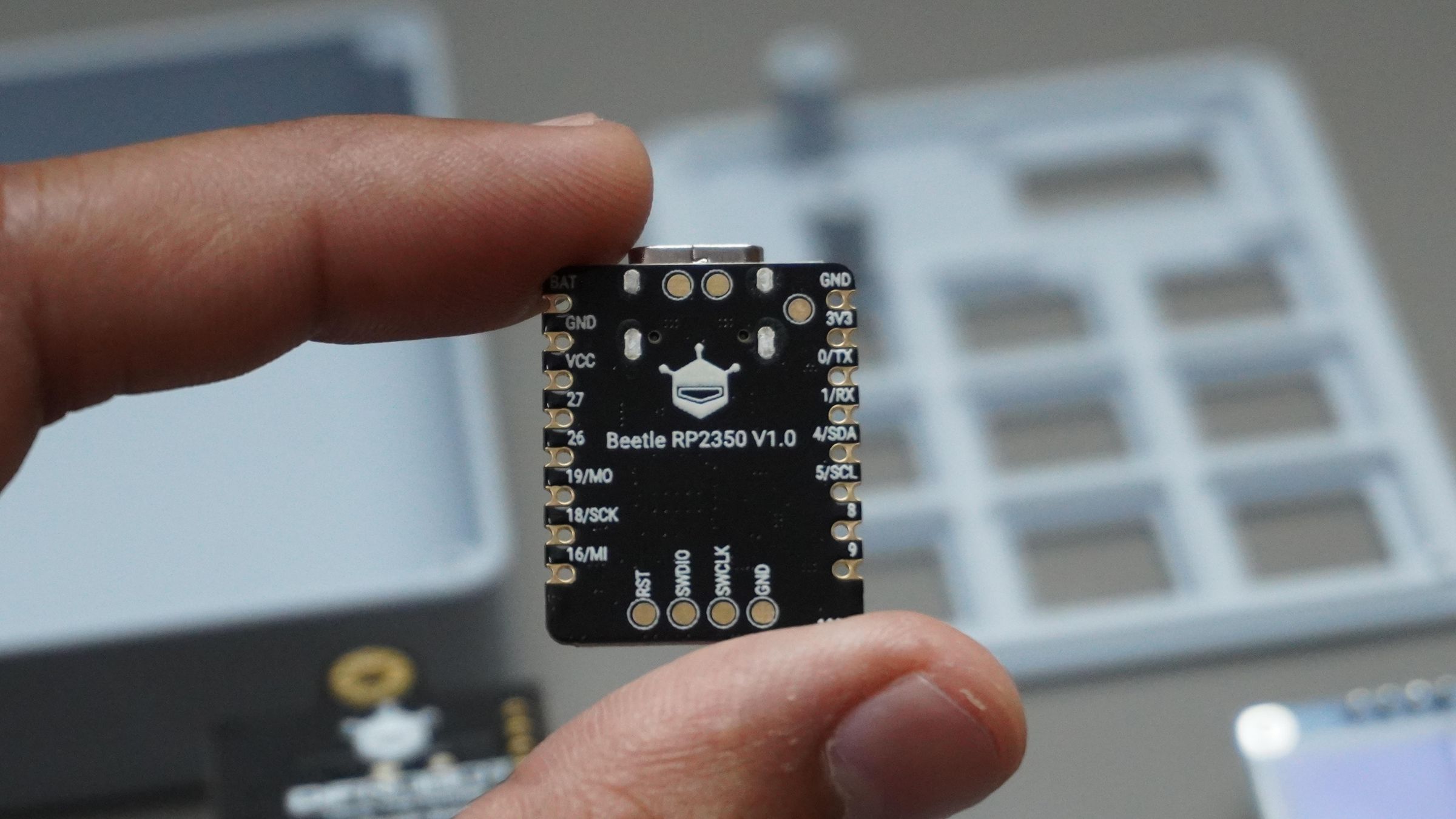
The board measures only 25 × 20.5 mm, which made it ideal for creating a compact macropad enclosure without wasting space.
One of the biggest advantages of this board is the price. At around $4.90 USD, it delivers incredible value for custom input devices, wearable electronics, and embedded projects.
Because the board is inexpensive and easy to source, this project stays accessible to makers who want to experiment with custom hardware without investing in expensive custom PCBs or manufacturing.
The Beetle RP2350 also supports:
- Arduino
- MicroPython
- C/C++
which makes firmware development beginner-friendly while still being powerful enough for advanced macro systems and HID projects.
Step 3: Flashing the Macropad Firmware
Now it’s time to bring the macropad to life.
This project uses CircuitPython, which makes development incredibly beginner-friendly. You can edit the code like a normal USB drive without installing complicated toolchains.
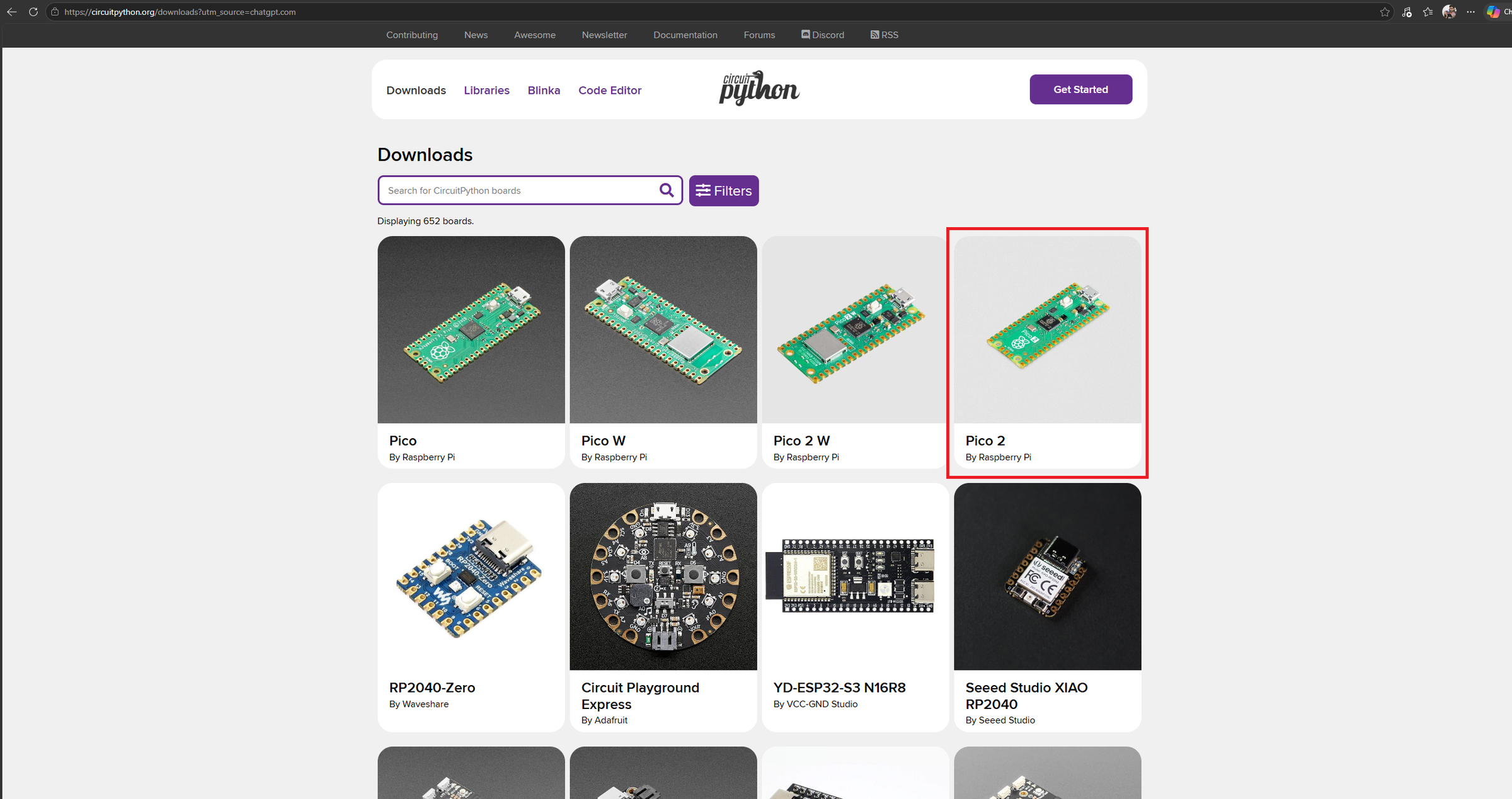
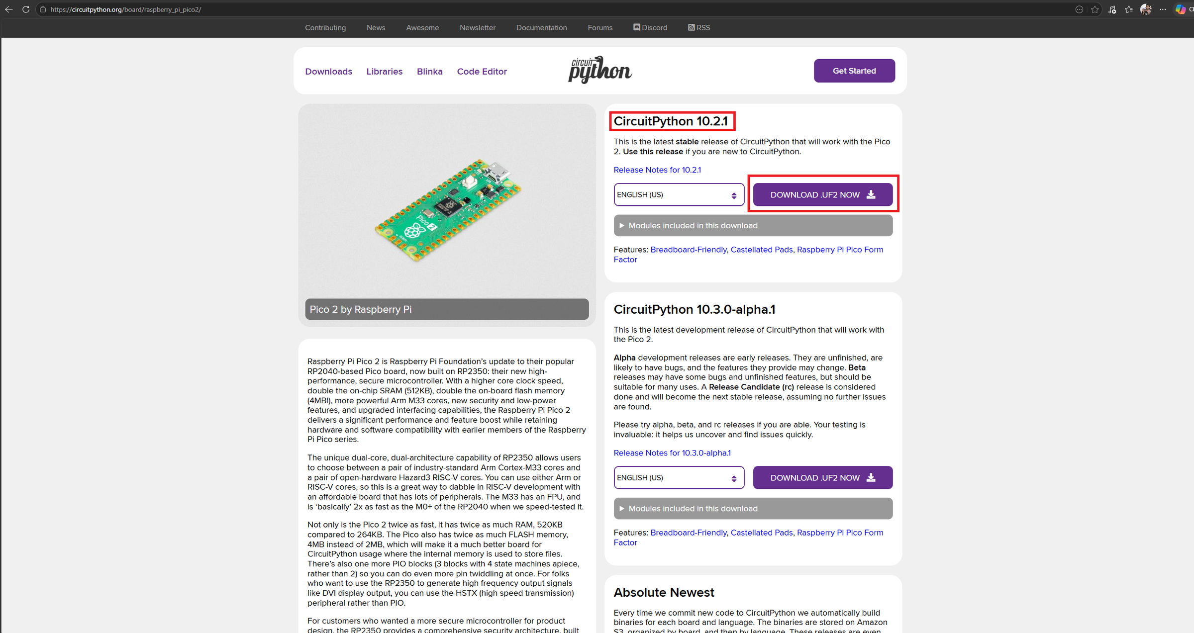
Step 1: Flash CircuitPython onto the RP2350
First, download the latest CircuitPython .uf2 firmware for RP2350 boards:
Search for:
Pico 2
Download the latest correct .uf2 file for your board.
 Flashing Process
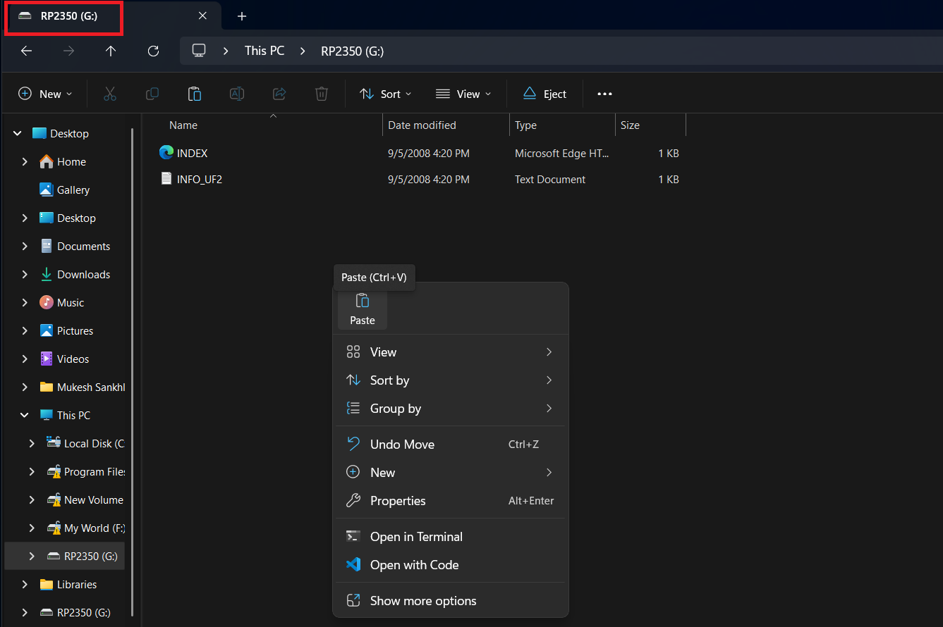
- Hold the BOOTSEL button on the board
- Plug the board into your PC using USB
- Release the BOOTSEL button
A USB drive named:
RP2350
will appear on your computer.
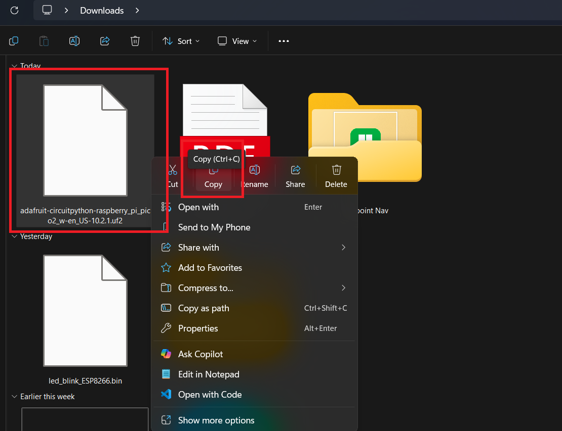
Simply drag and drop the downloaded .uf2 file onto that drive or Copy -> Paste.
The board will automatically reboot, and a new drive called:
CIRCUITPY
will appear.
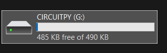
Your board is now running CircuitPython.
Step 2: Download the Adafruit Library Bundle
Next, download the official Adafruit CircuitPython library bundle:
Adafruit CircuitPython Bundle Releases
Download the file named something like:
adafruit-circuitpython-bundle-10.x-mpy-YYYYMMDD.zip
Make sure the version matches your installed CircuitPython version.
You can check your version by opening:
CIRCUITPY/boot_out.txt
Extract the ZIP file on your computer. Inside, you’ll find a lib/ folder containing all the libraries.
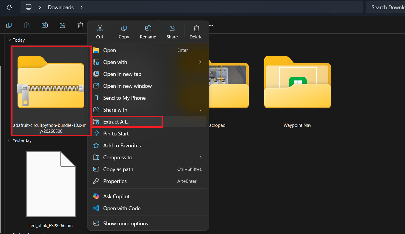
Step 3: Copy Only the Required Libraries
From the extracted lib/ folder, copy these files and folders into:
CIRCUITPY/lib/
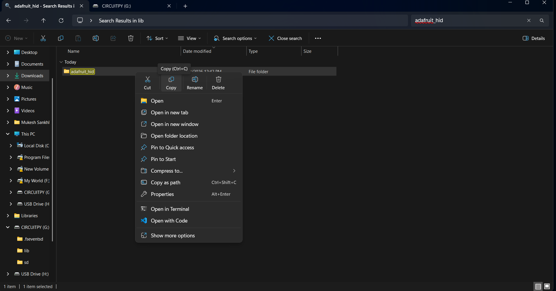
Required libraries:
adafruit_hid/ ← whole folder
adafruit_displayio_ssd1306.mpy
adafruit_display_text/ ← whole folder
adafruit_imageload/ ← whole folder
adafruit_display_shapes/ ← whole folder
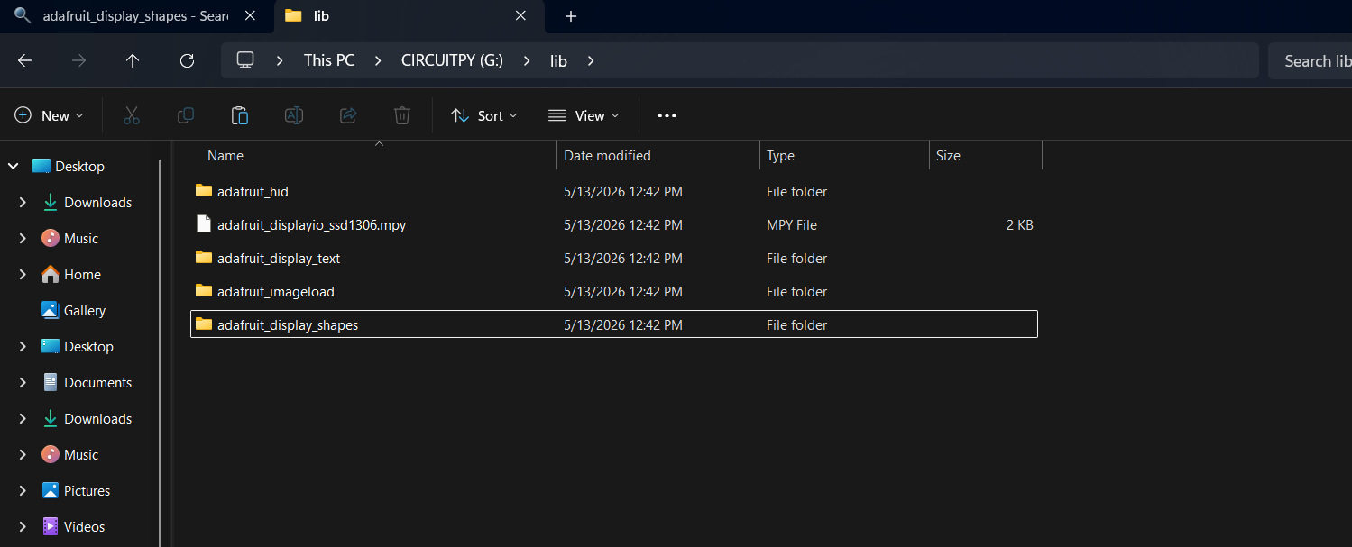
Your final structure should look like:

Step 4: Copy boot.py and Replace the code.py
Download the complete macropad firmware from the GitHub repository:
Extract the downloaded ZIP file on your computer.
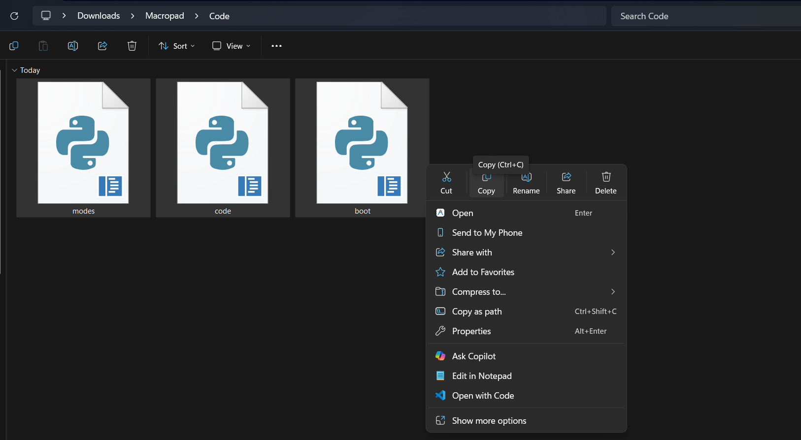
Inside the repository, you’ll find:
- boot.py
- code.py
- modes.py
Copy the all file into the root of your:
CIRCUITPY
drive.
If a code.py file already exists, replace it.
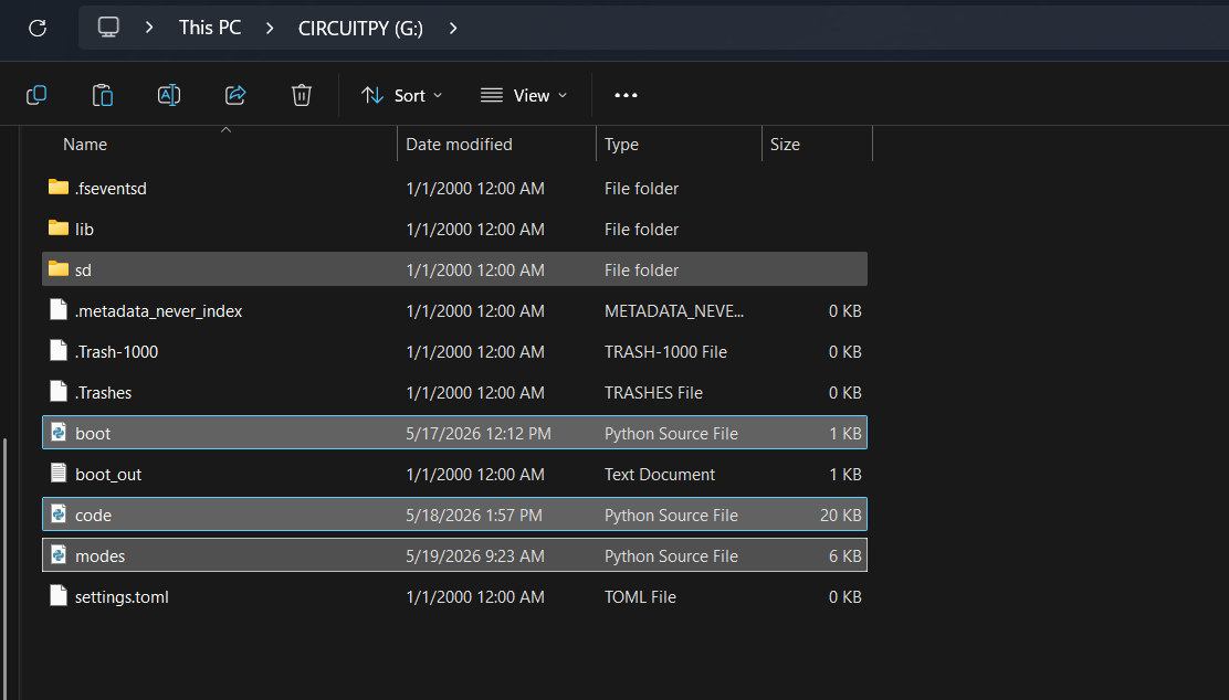
Final File Structure
When everything is copied correctly, your board should look like this:

Once the files are copied, the unplug the board.
Step 4: CAD Design

I designed the complete macropad in Autodesk Fusion with a focus on simplicity, compactness, and easy assembly without using a PCB.
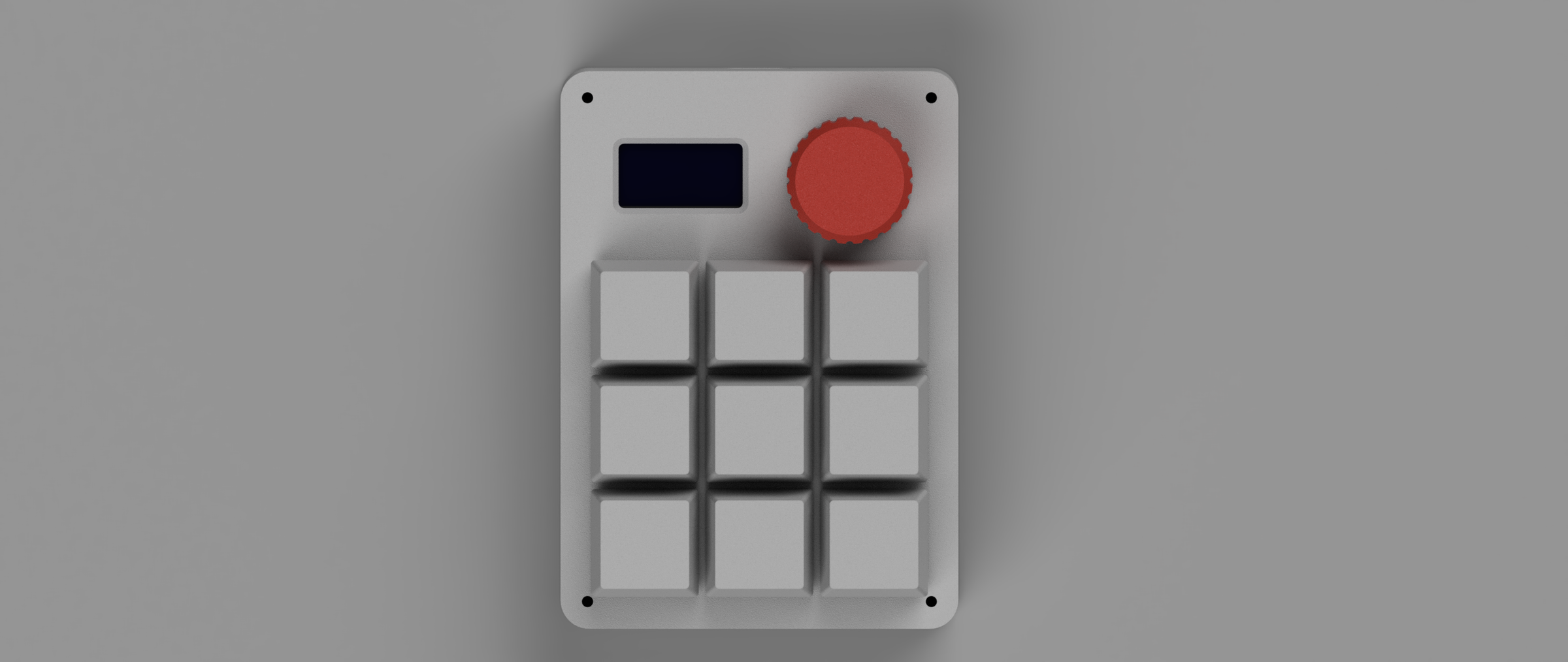
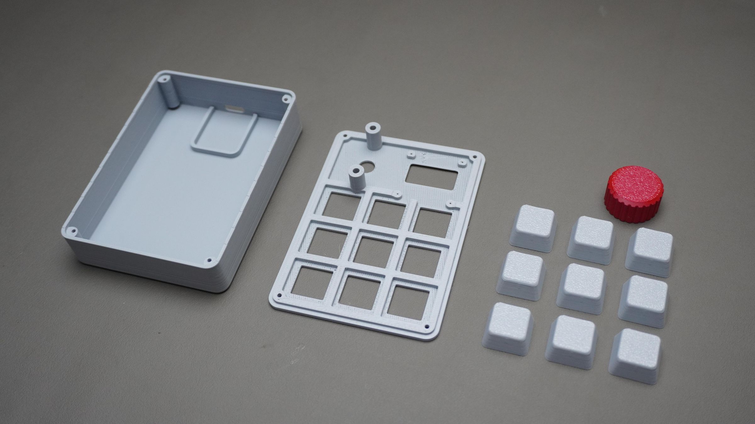
The entire design consists of 4 main parts:
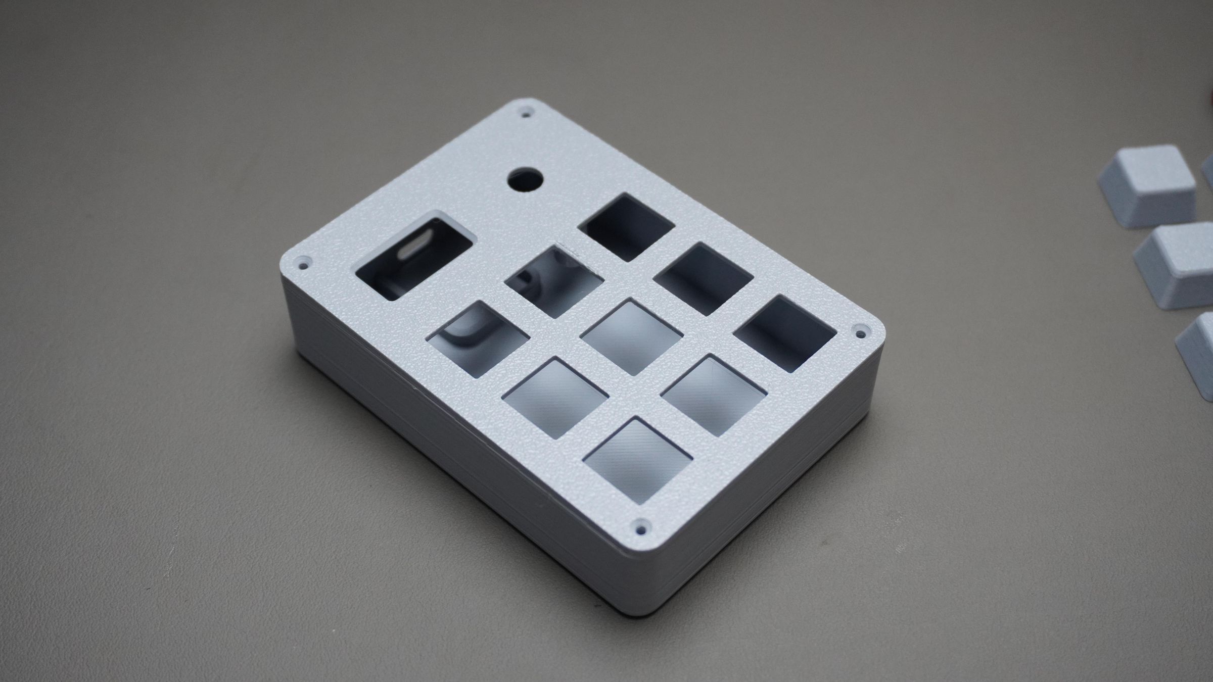
1. Top_Cover:
This is the main structural part of the macropad.
- Holds all 9x Outemu switches using snap-fit mounting
- Mounts the OLED display and rotary encoder from the back side
- Also acts as the top enclosure cover for the entire assembly
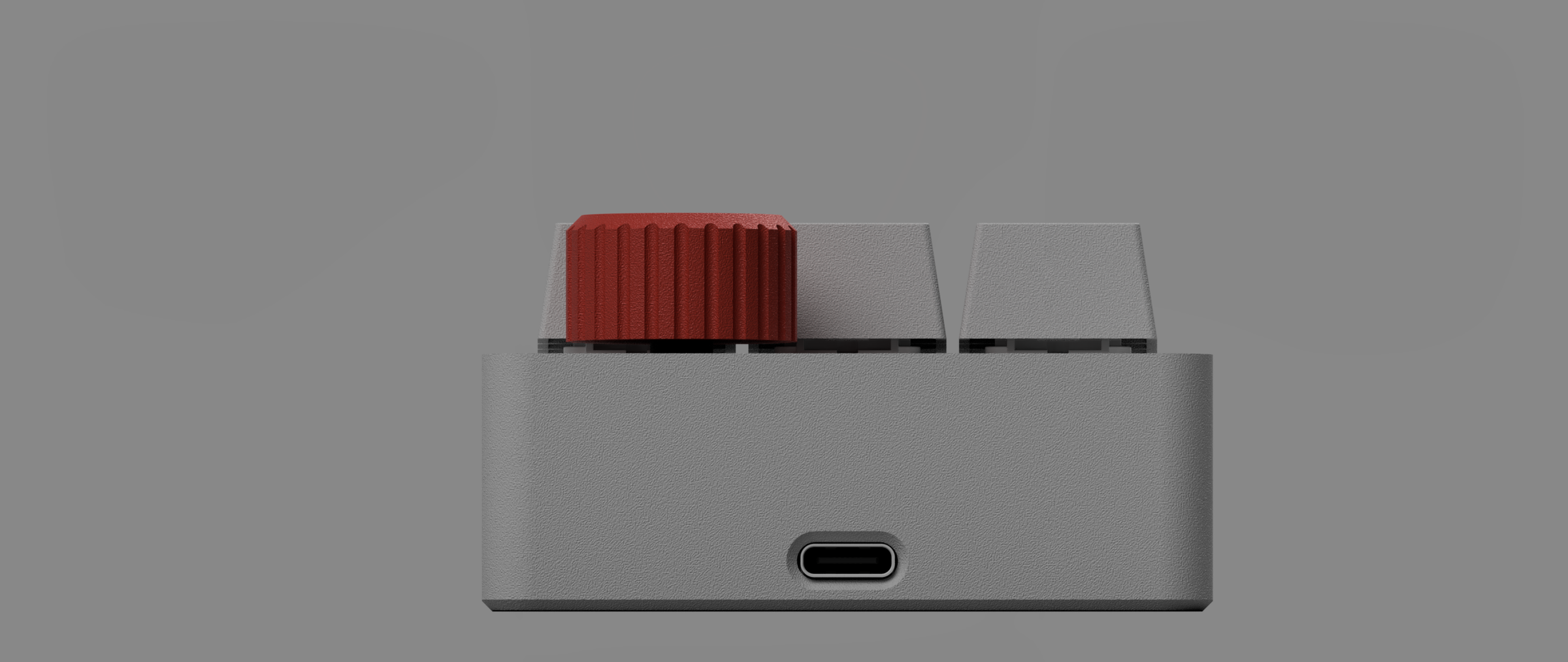
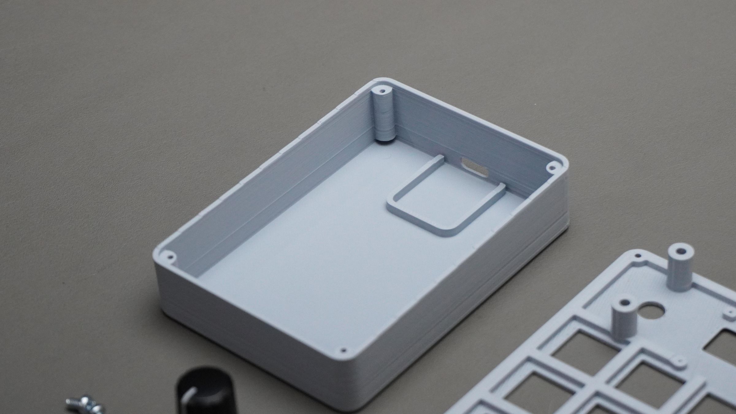
2. Housing:
- The bottom housing holds the DFRobot Beetle RP2350 securely in place.
- It also includes USB Type-C opening
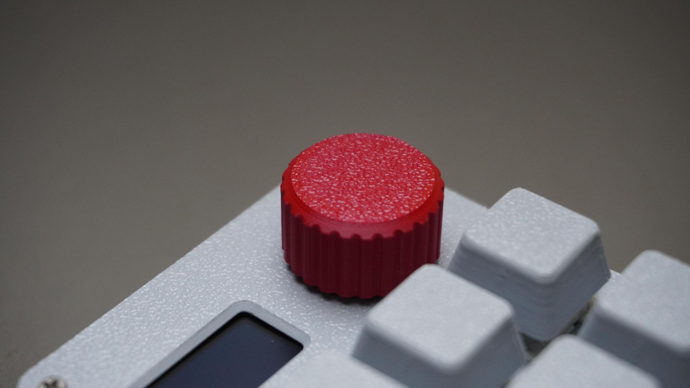
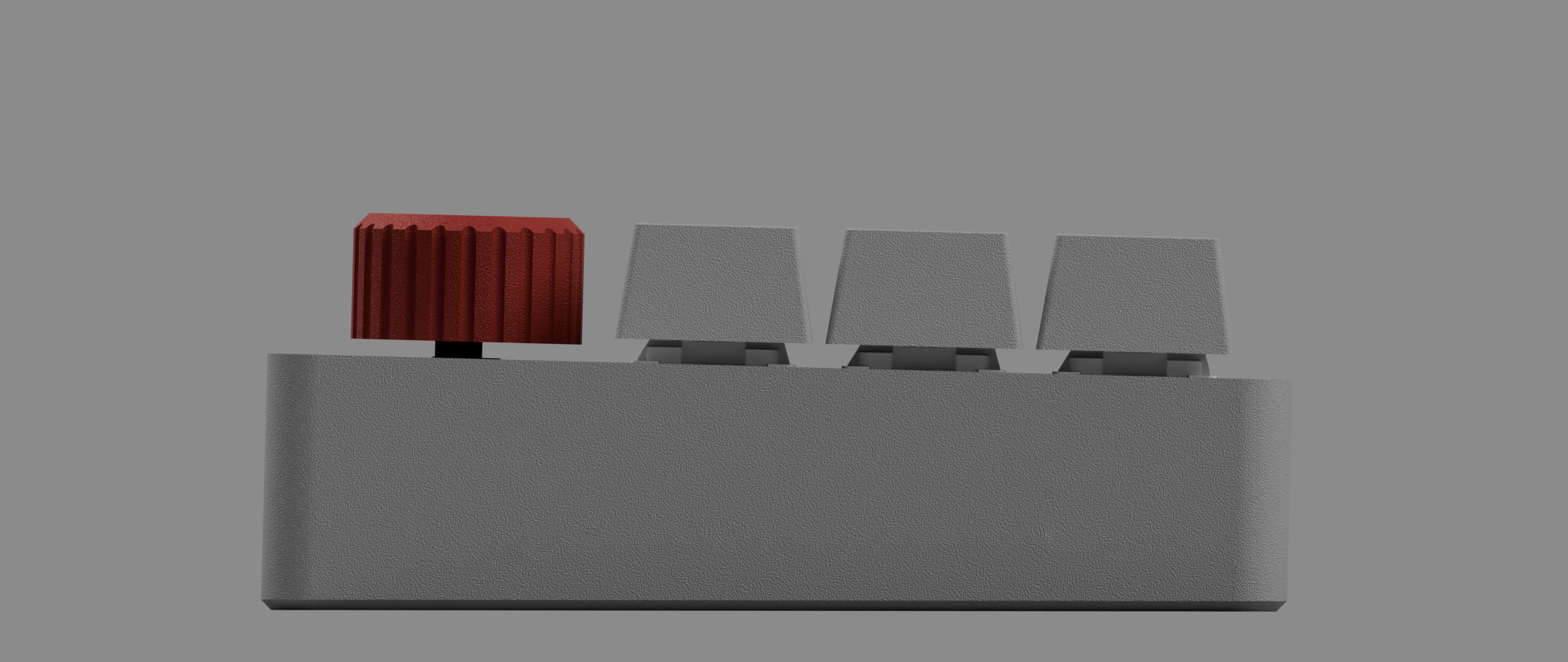
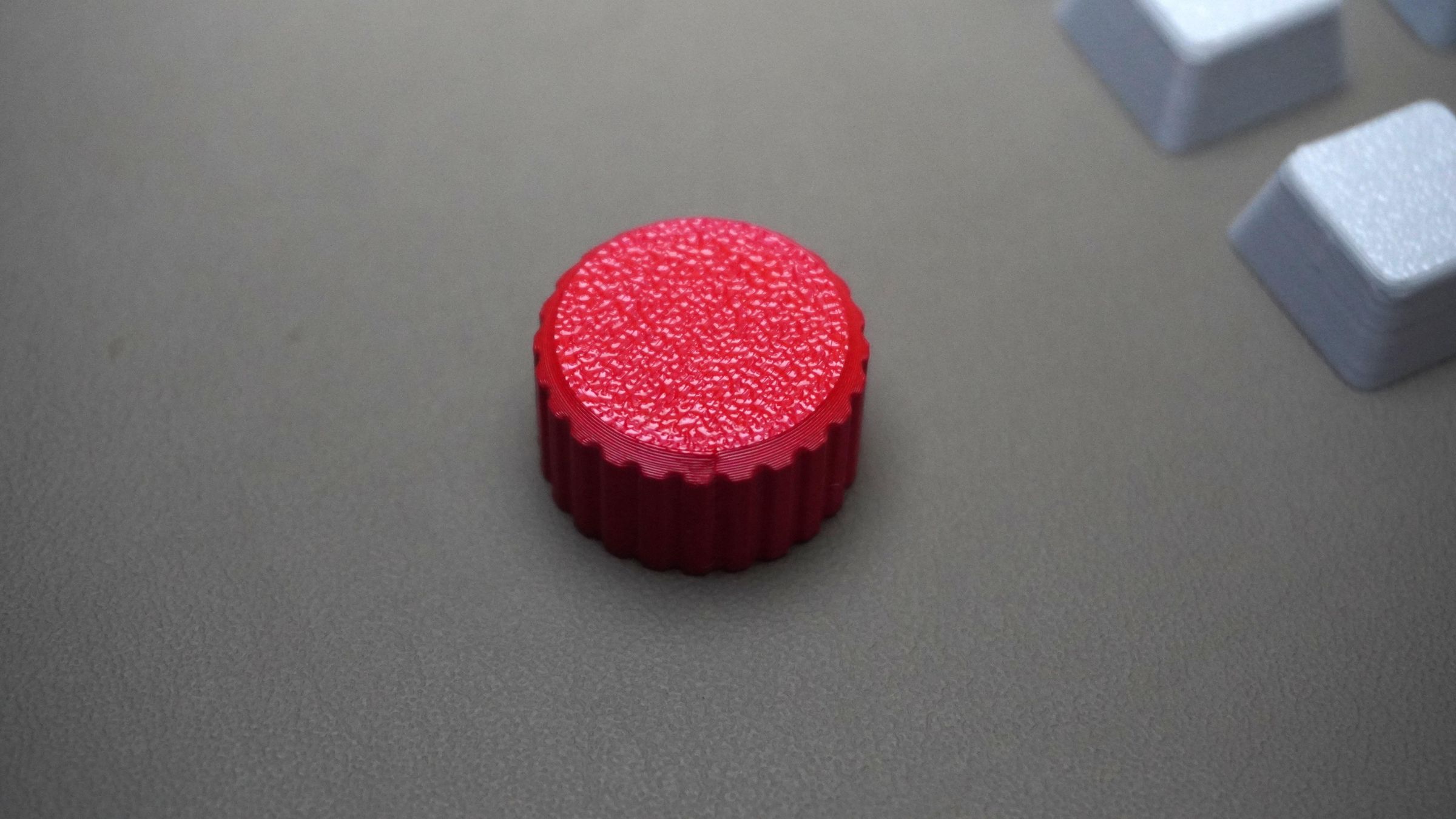
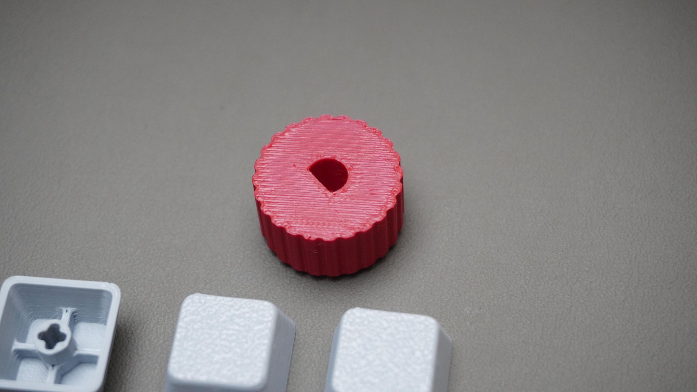
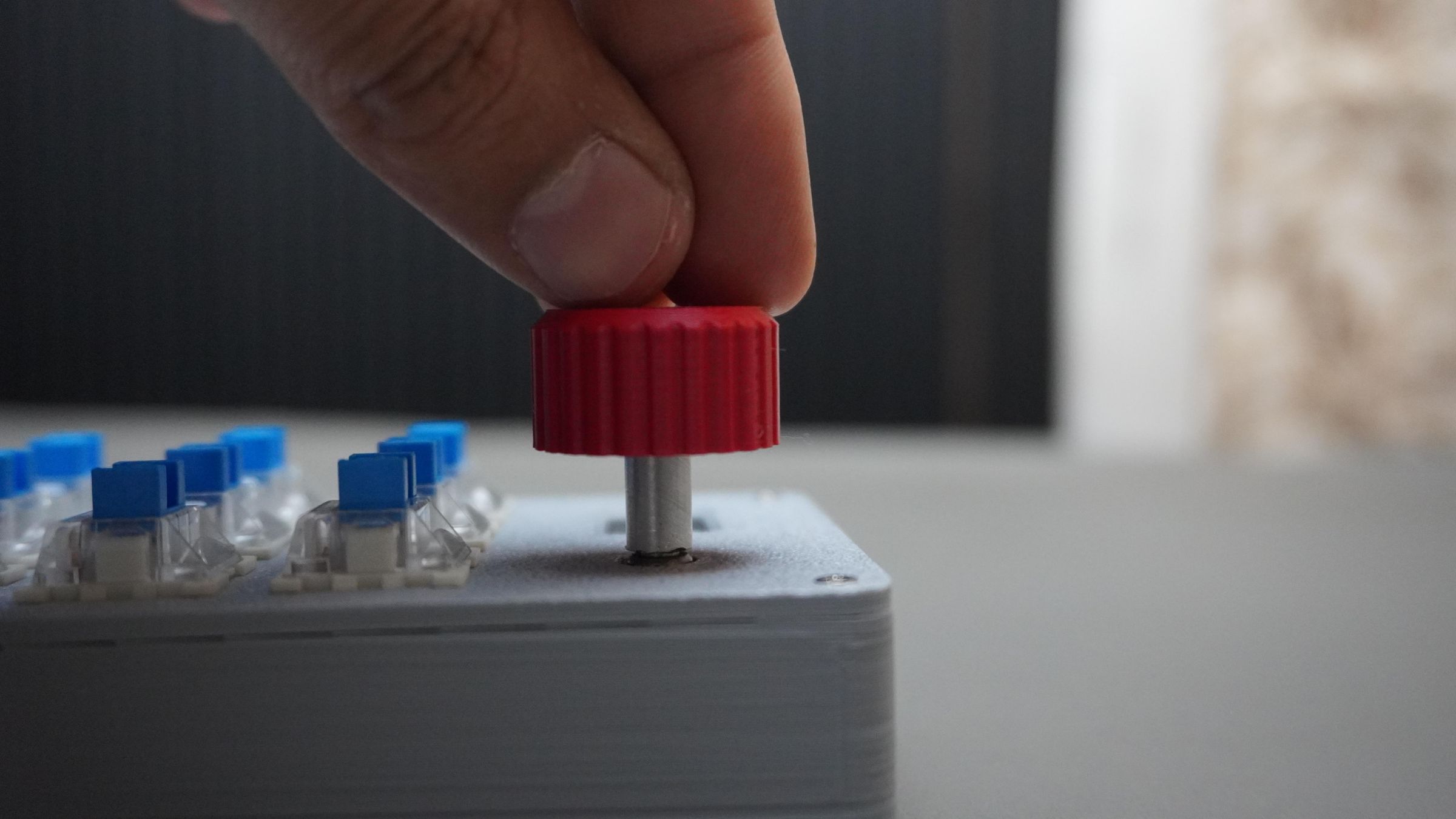
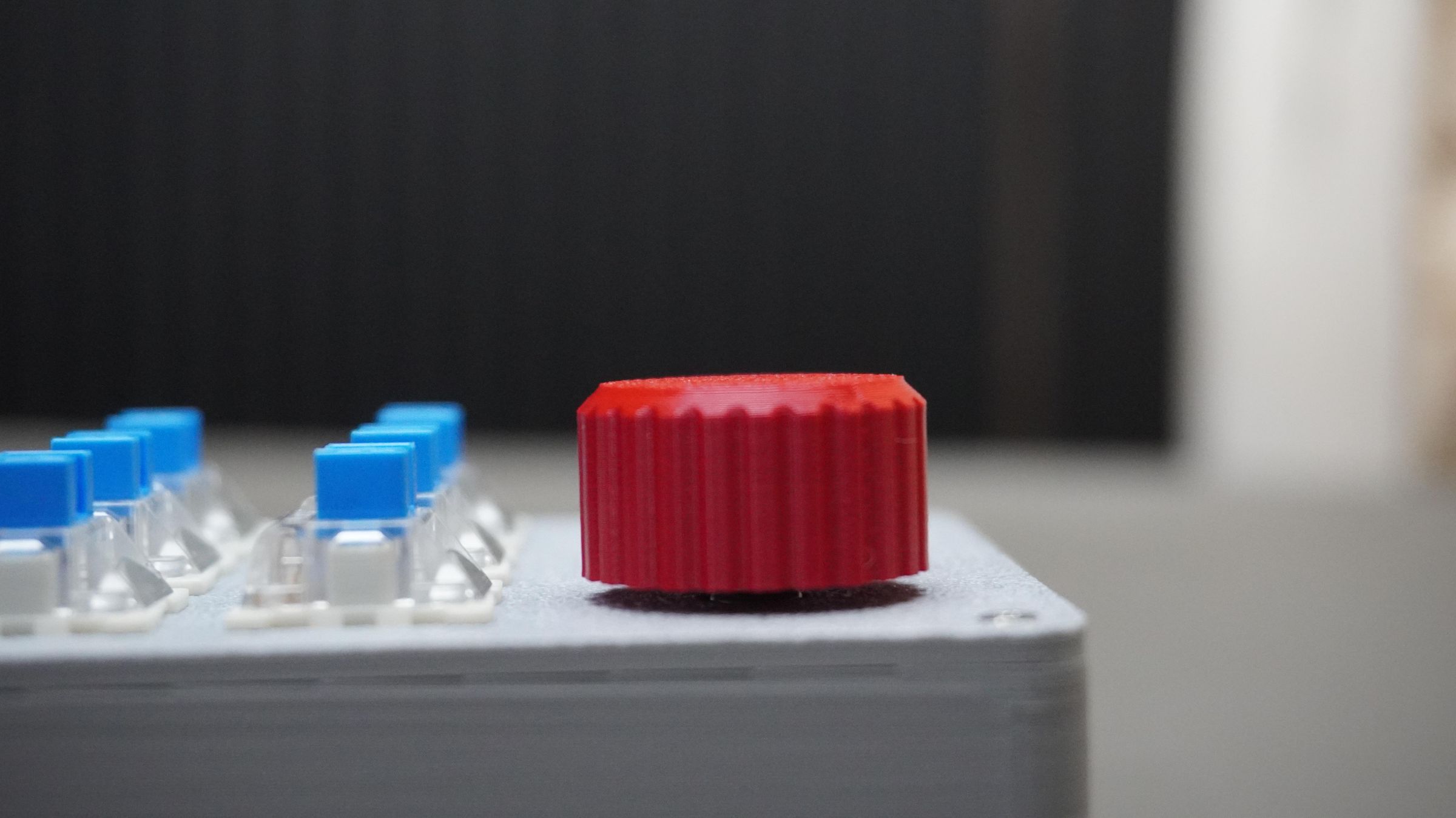
3. Knob: A custom-designed rotary encoder knob designed specifically for this build.
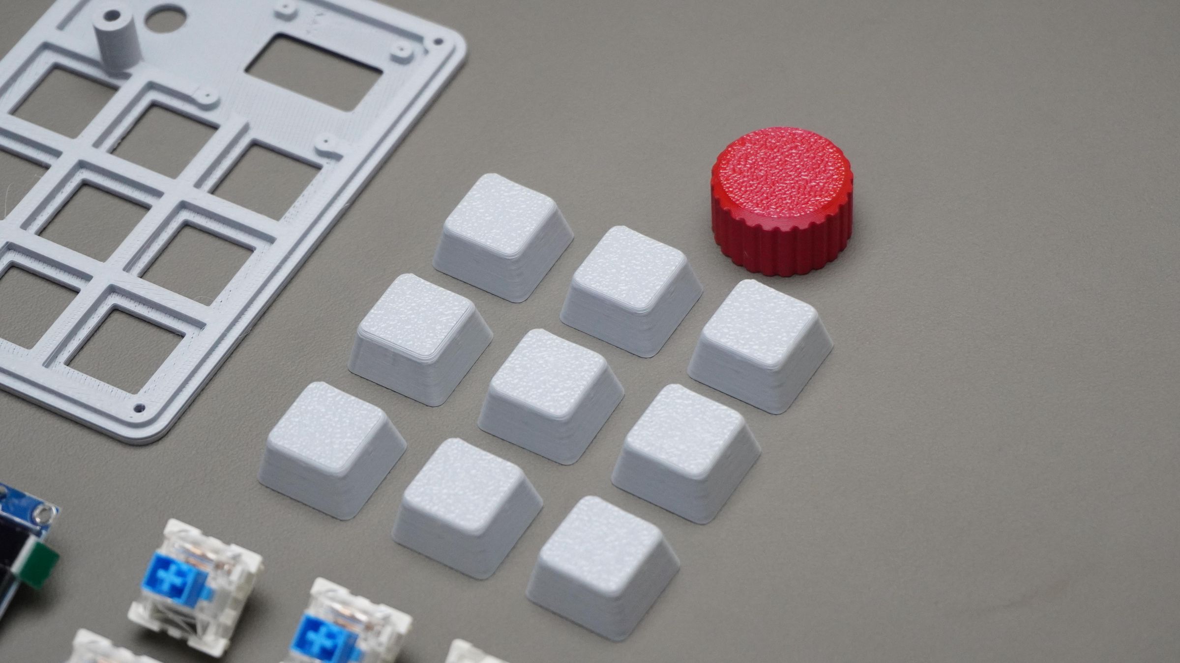
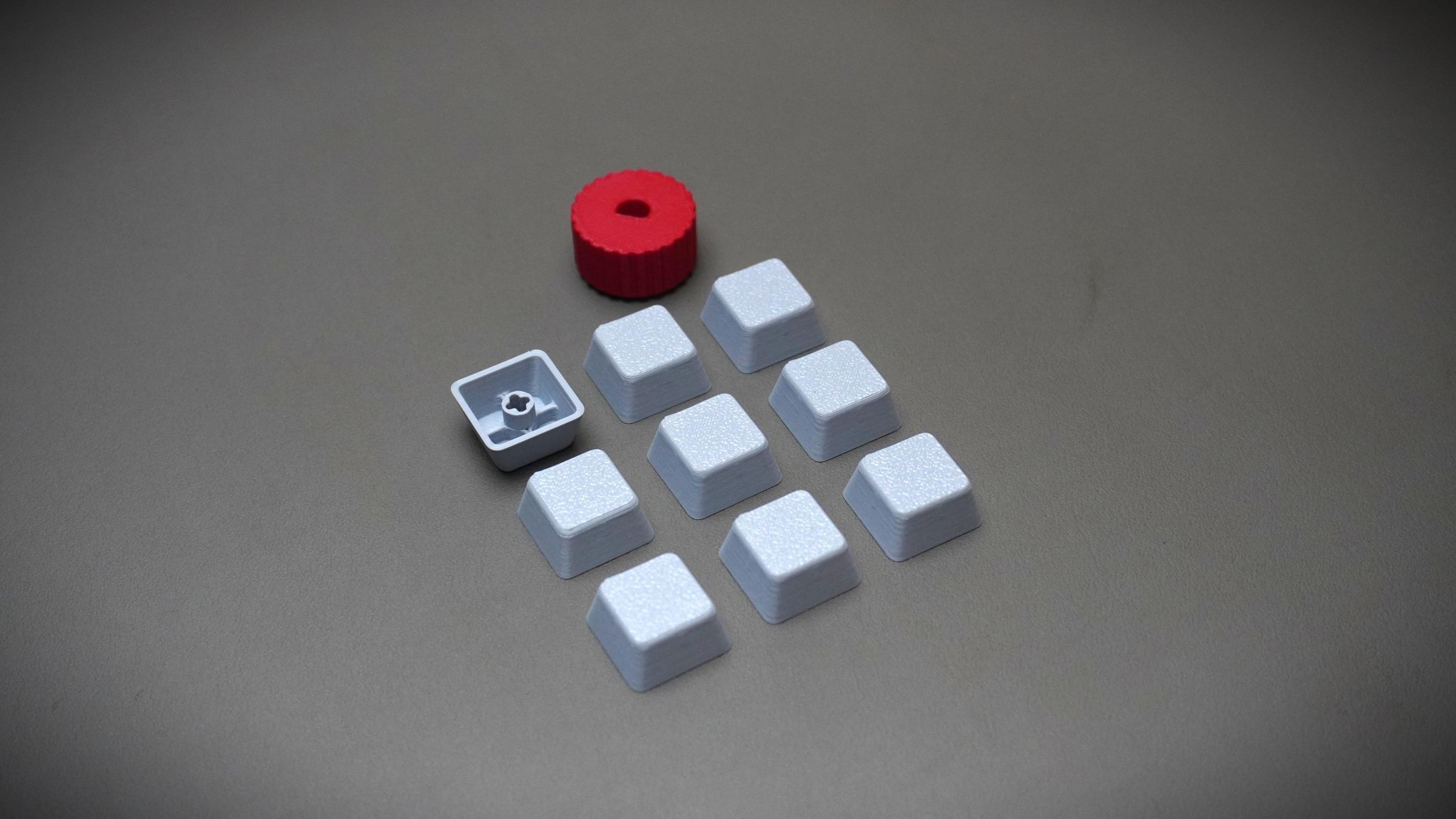
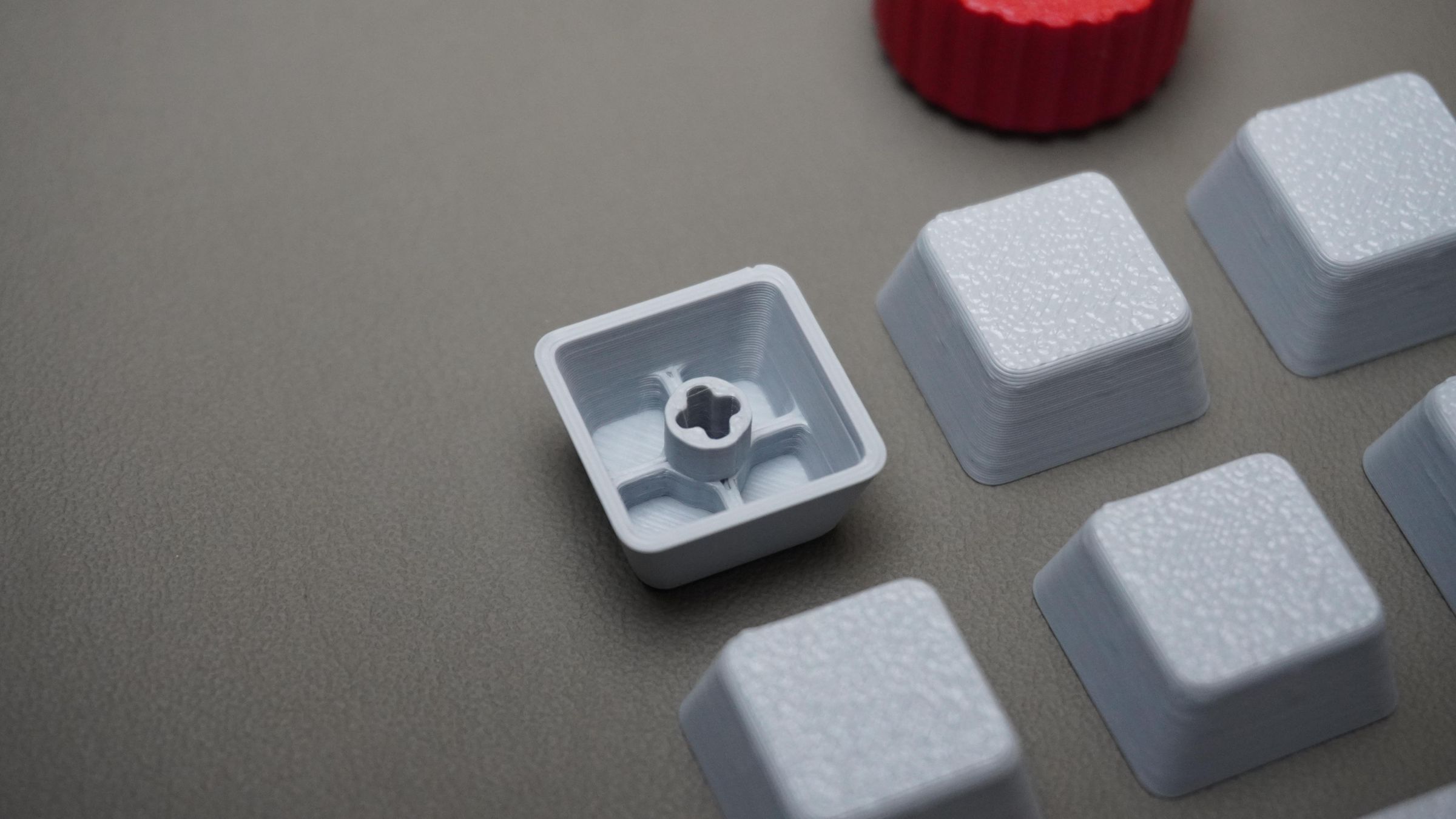
4. Keycaps:
Custom 3D printable keycaps for all 9 switches.
I have attached:
- The original Fusion 360 design file
- STL files for all individual parts
You can:
- View the design directly in the browser
- Modify the CAD model as per your needs
- Directly slice and 3D print the provided STL files
Step 5: 3D Printing
Now it’s time to print all the parts.
Print the following:
- 1x Top_Cover
- 1x Housing
- 1x Knob
- 9x Key_Caps
I printed all parts using standard PLA settings, so no special print profile is required.
My print setup:
- Printer: Bambu Lab P1S
- Material: PLA
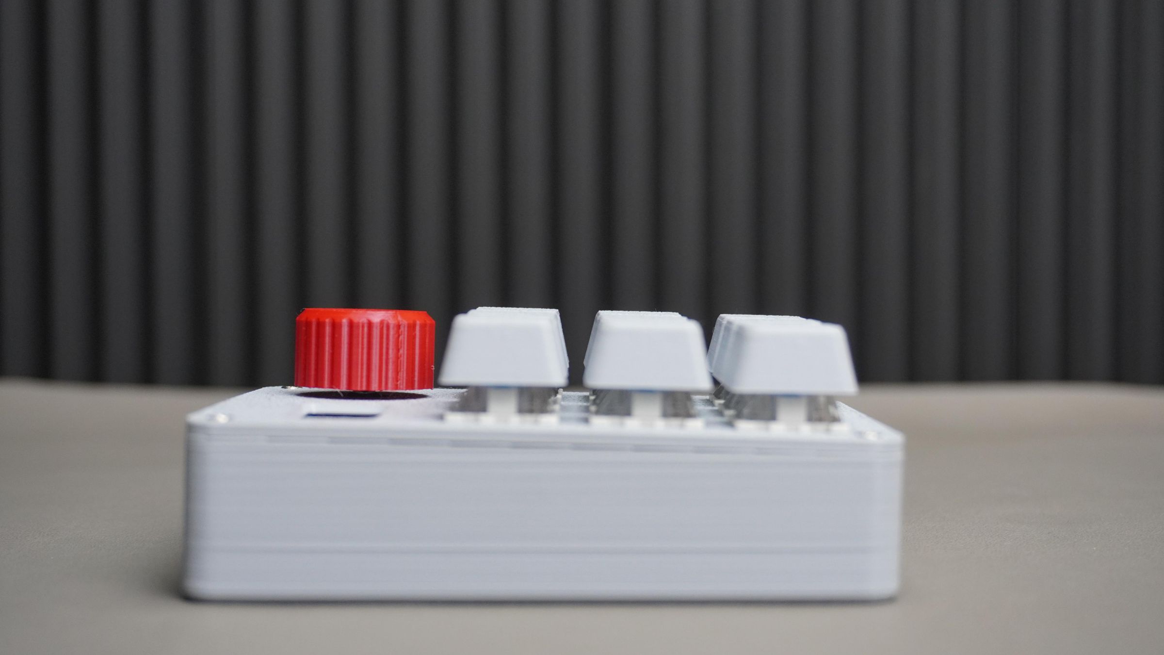
- Main body color: Light Gray
- Knob color: Red (for contrast)

Step 6: Mounting the Switches
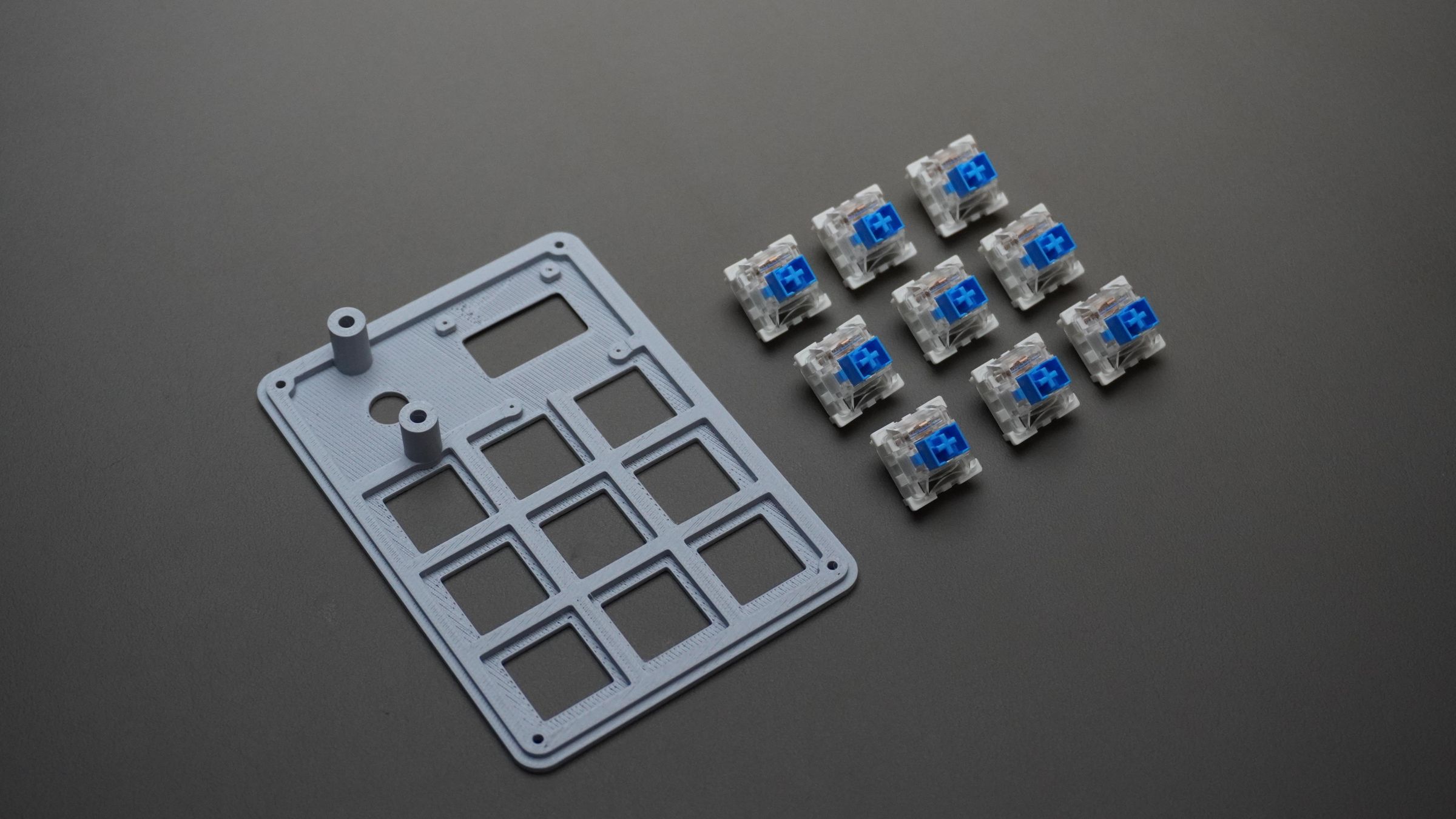
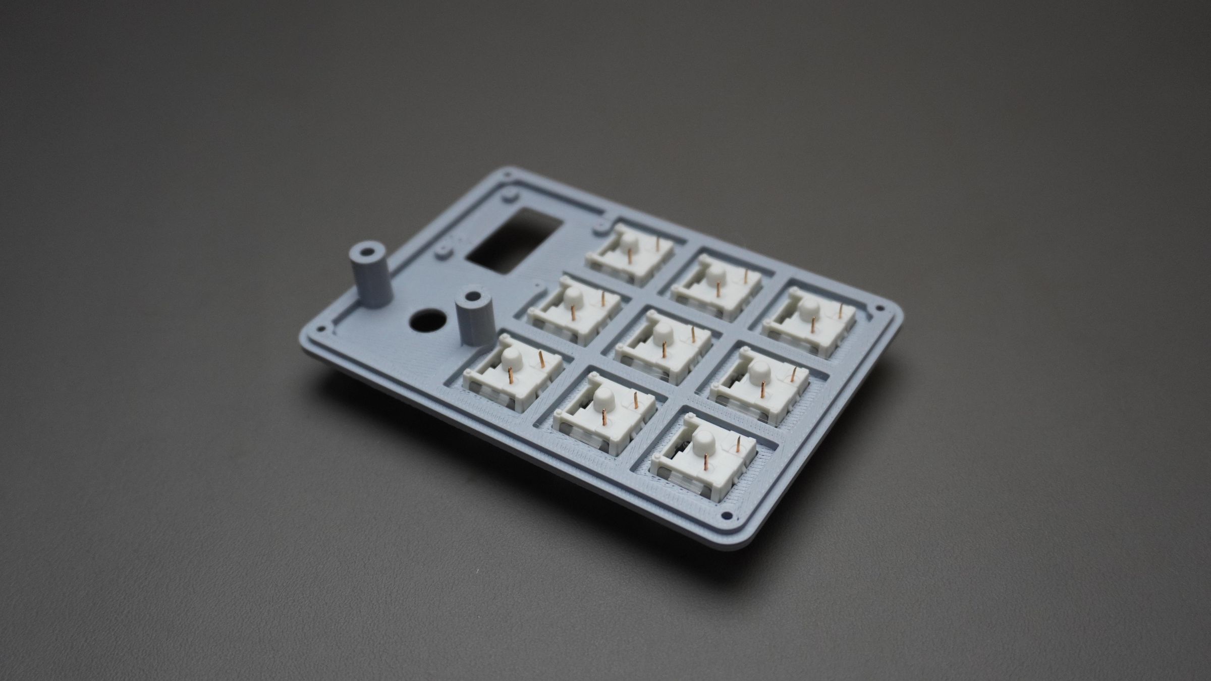
Take all 9 mechanical switches and insert them into the Top_Cover from the top side.
Each switch is designed to:
- Snap directly into the printed plate
- Align automatically
- Lock itself in place after pressing
Simply push each switch firmly until you hear or feel a click.
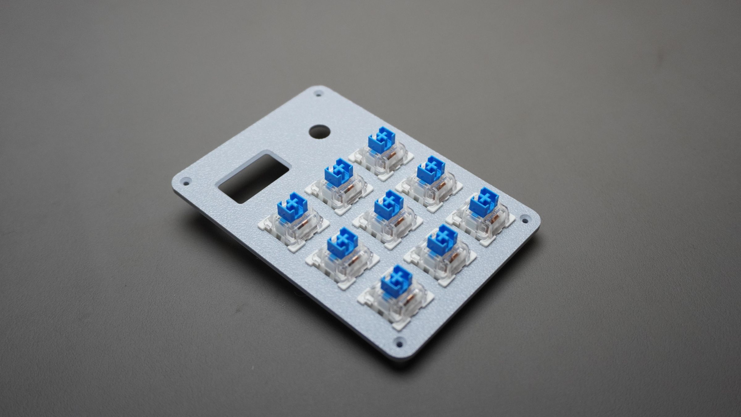
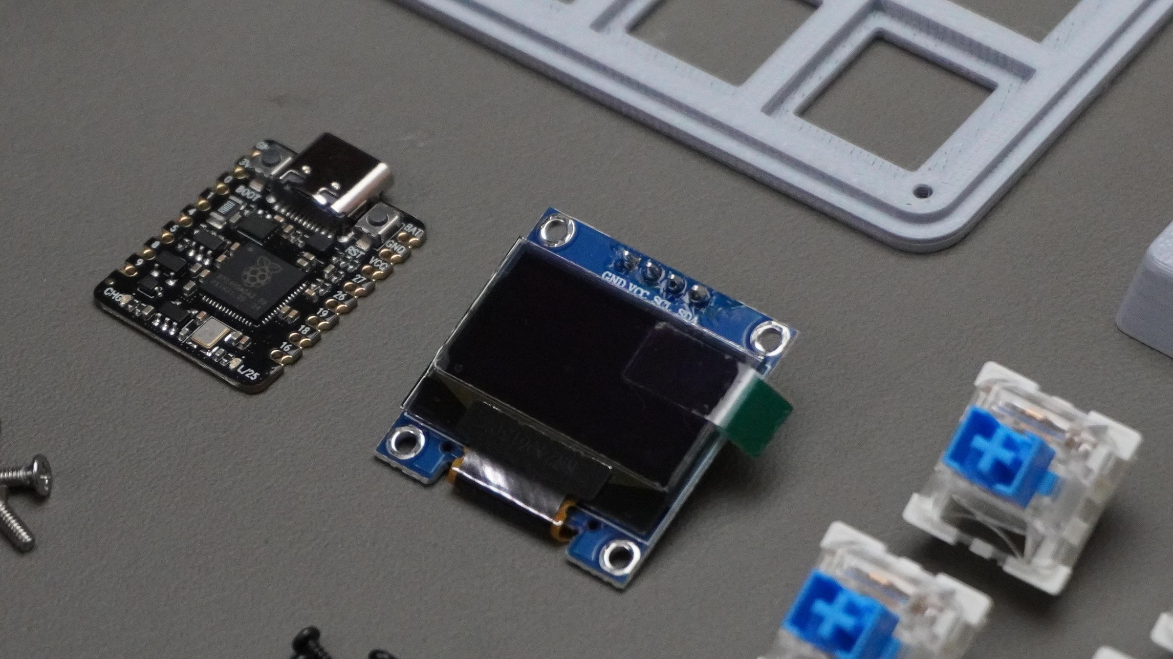
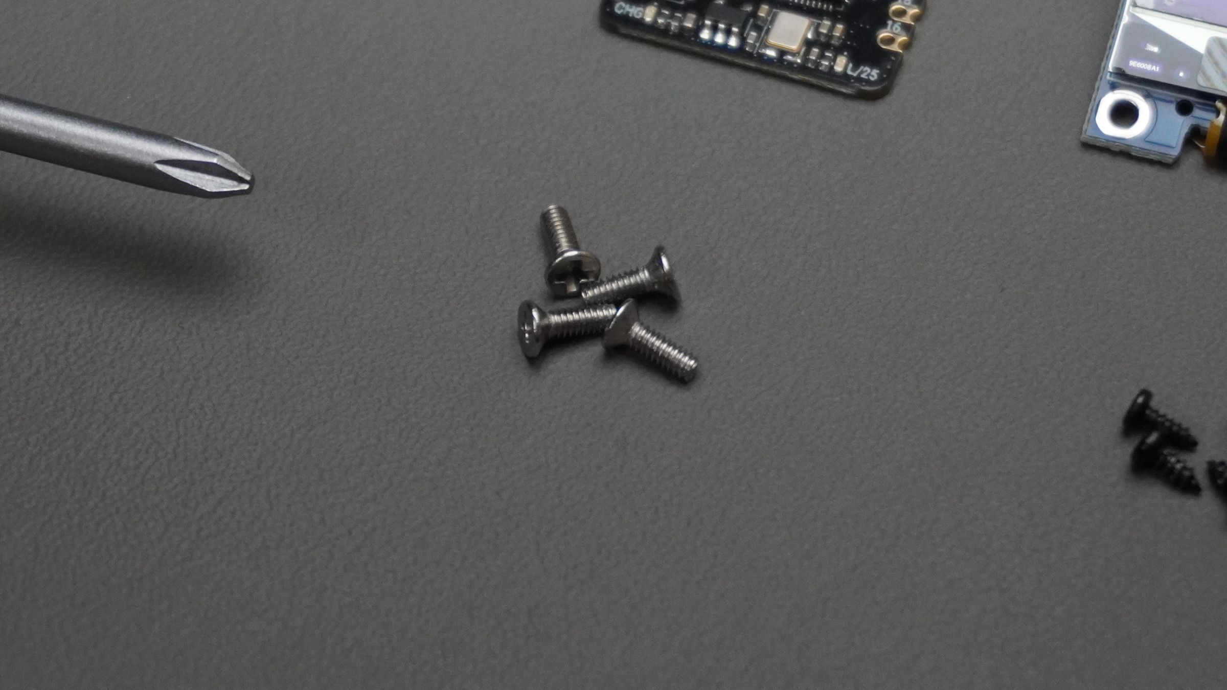
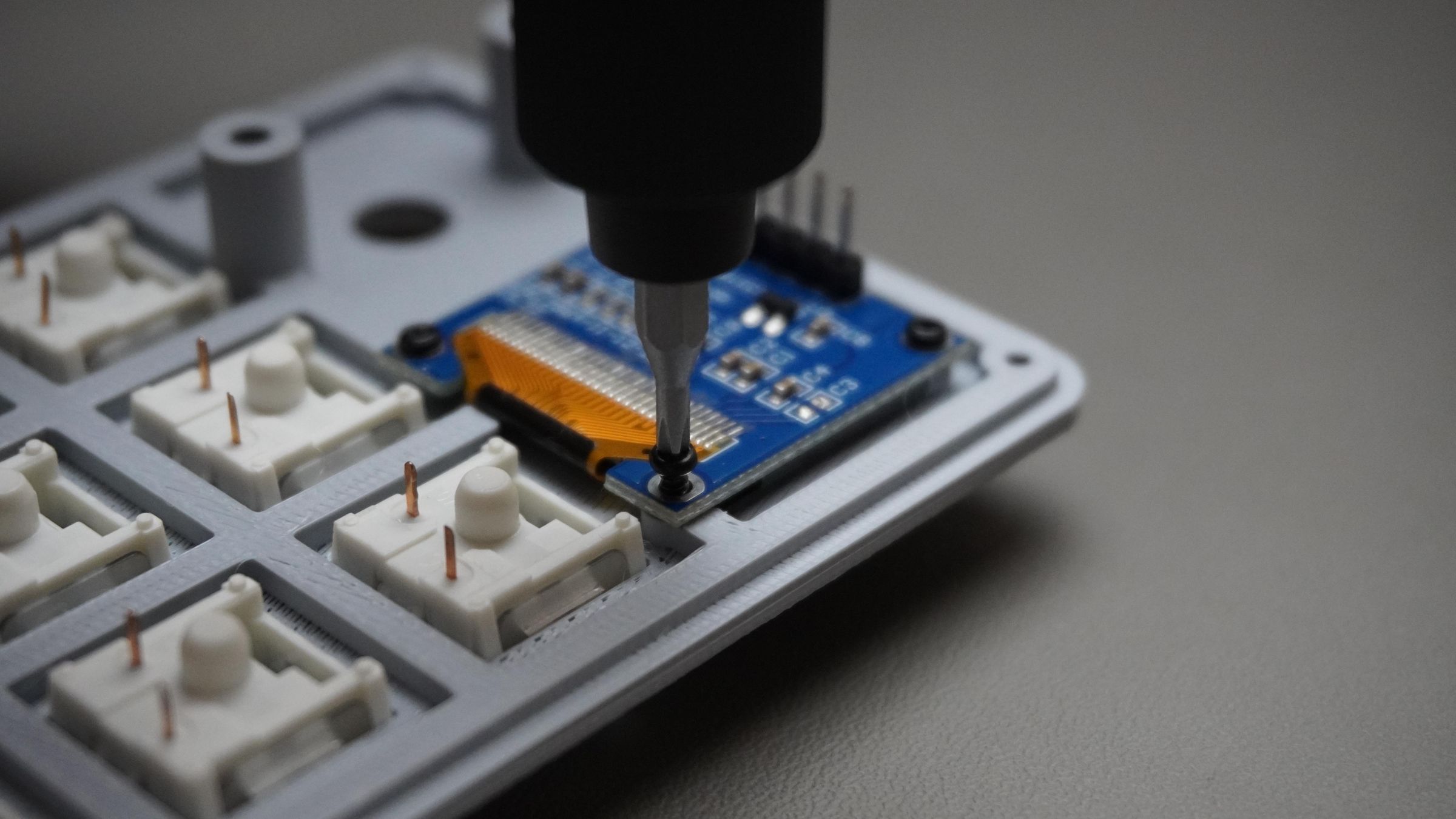
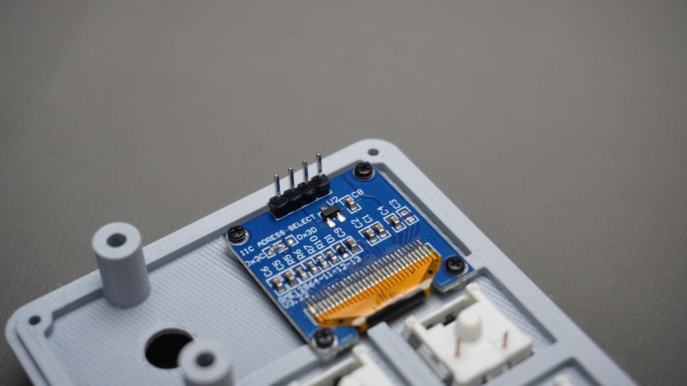
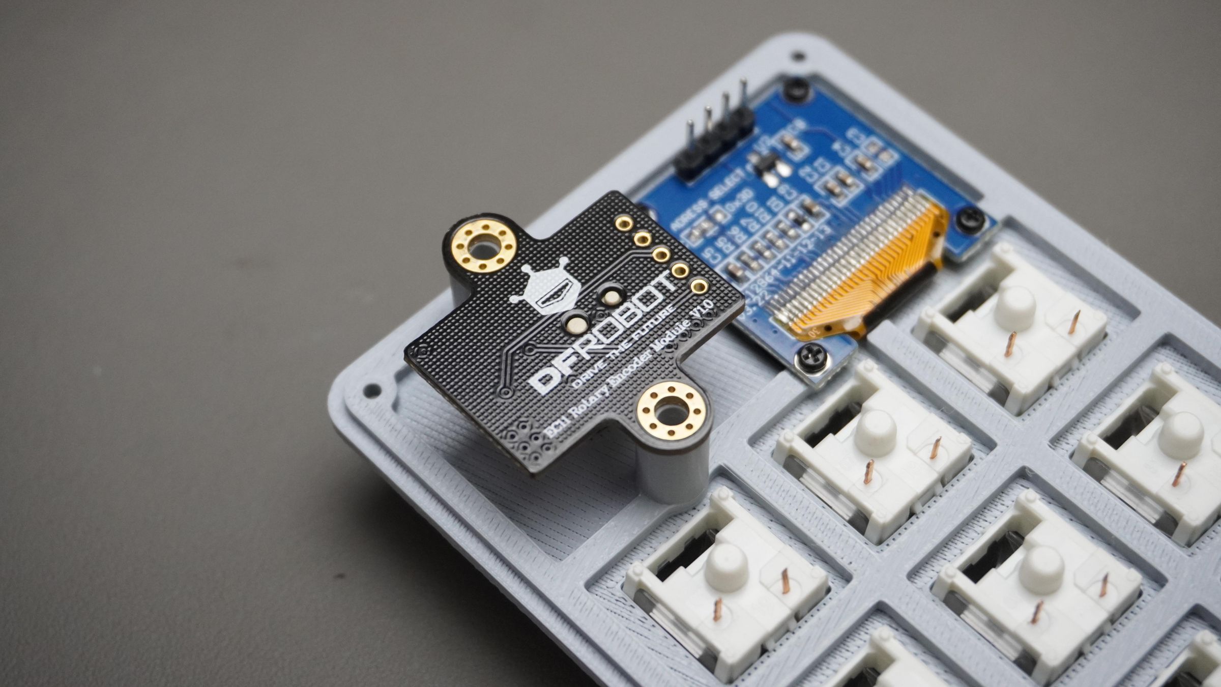
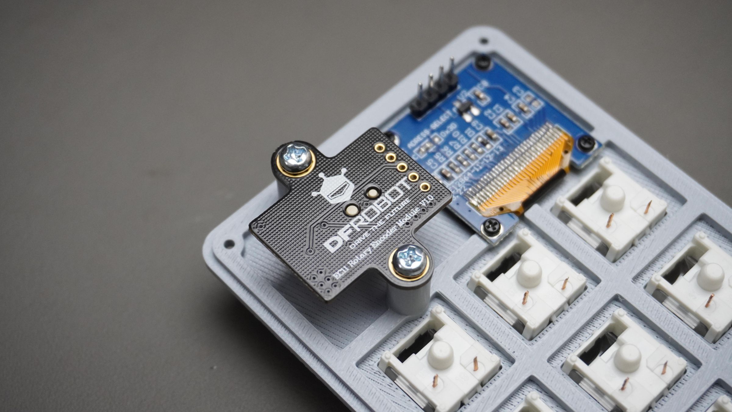
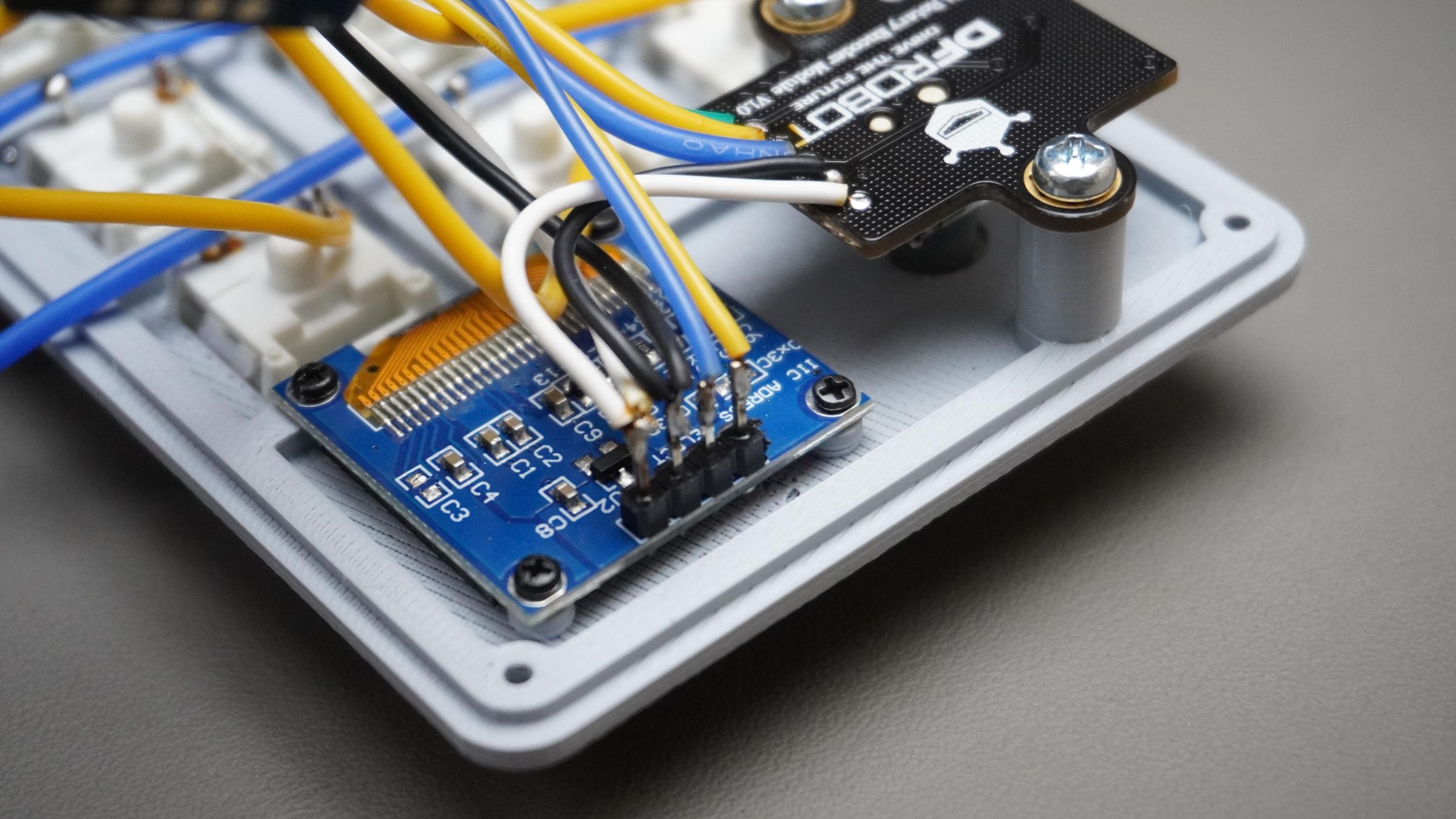
Step 7: Mounting the OLED Display
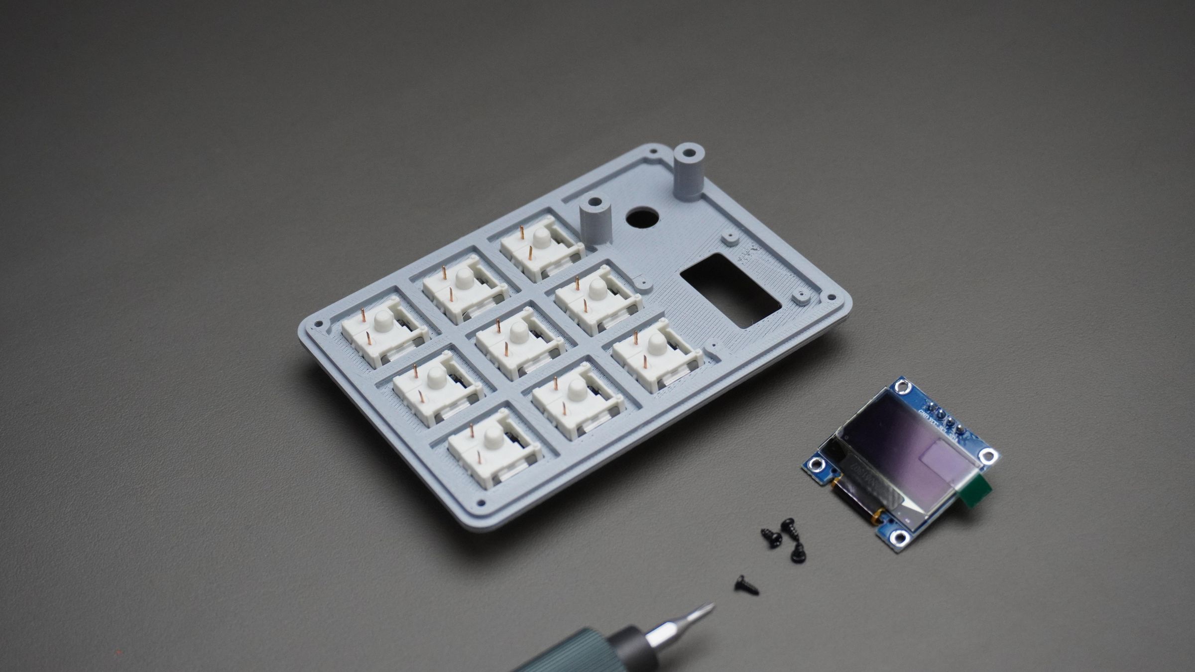
Take:
- The 0.96" OLED display
- 4x M2 × 4mm screws
Place the OLED on the back side of the Top_Cover and align it with the mounting holes.
Insert the screws and tighten them gently until the display is securely mounted.
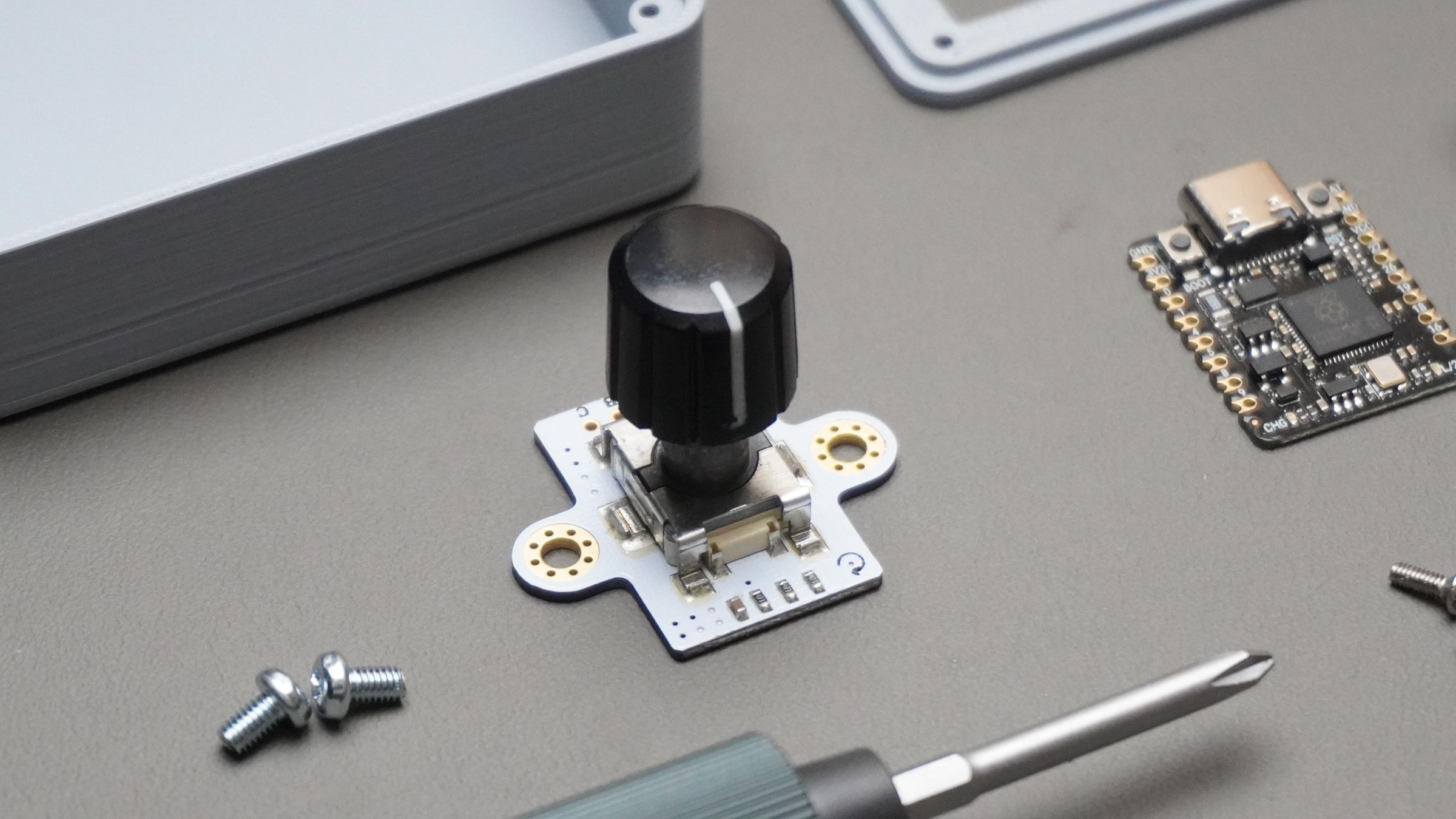
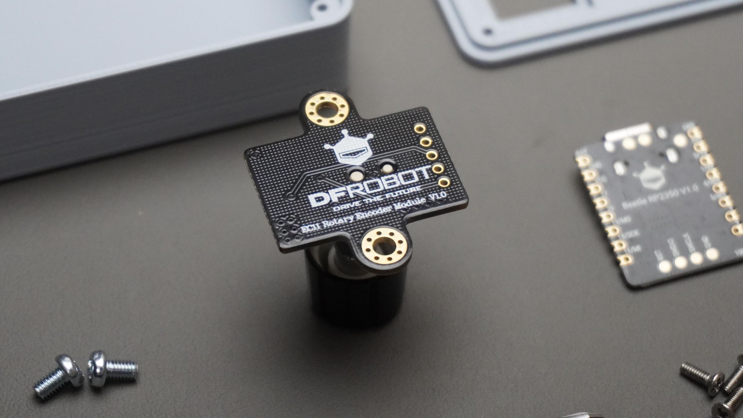
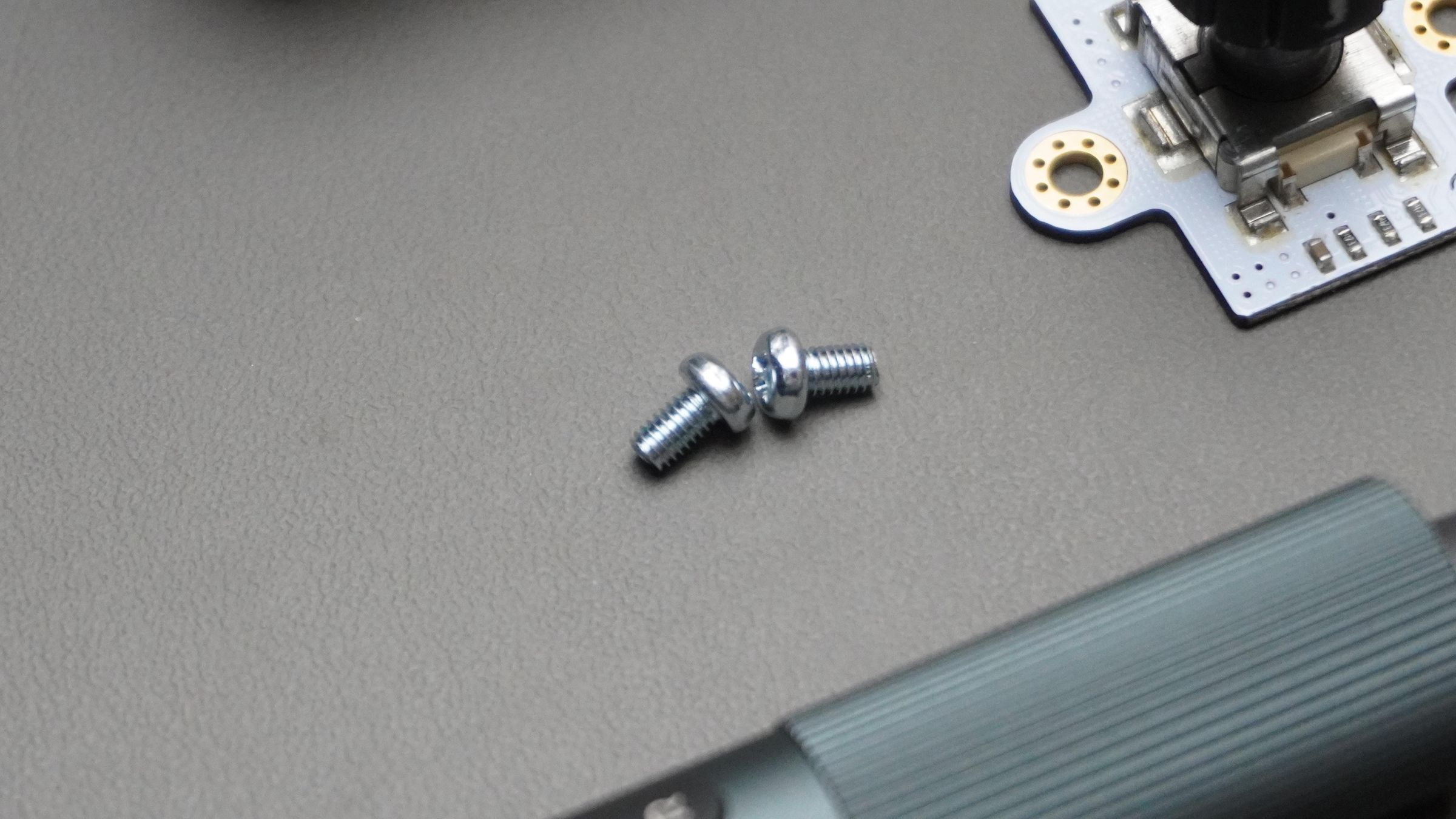
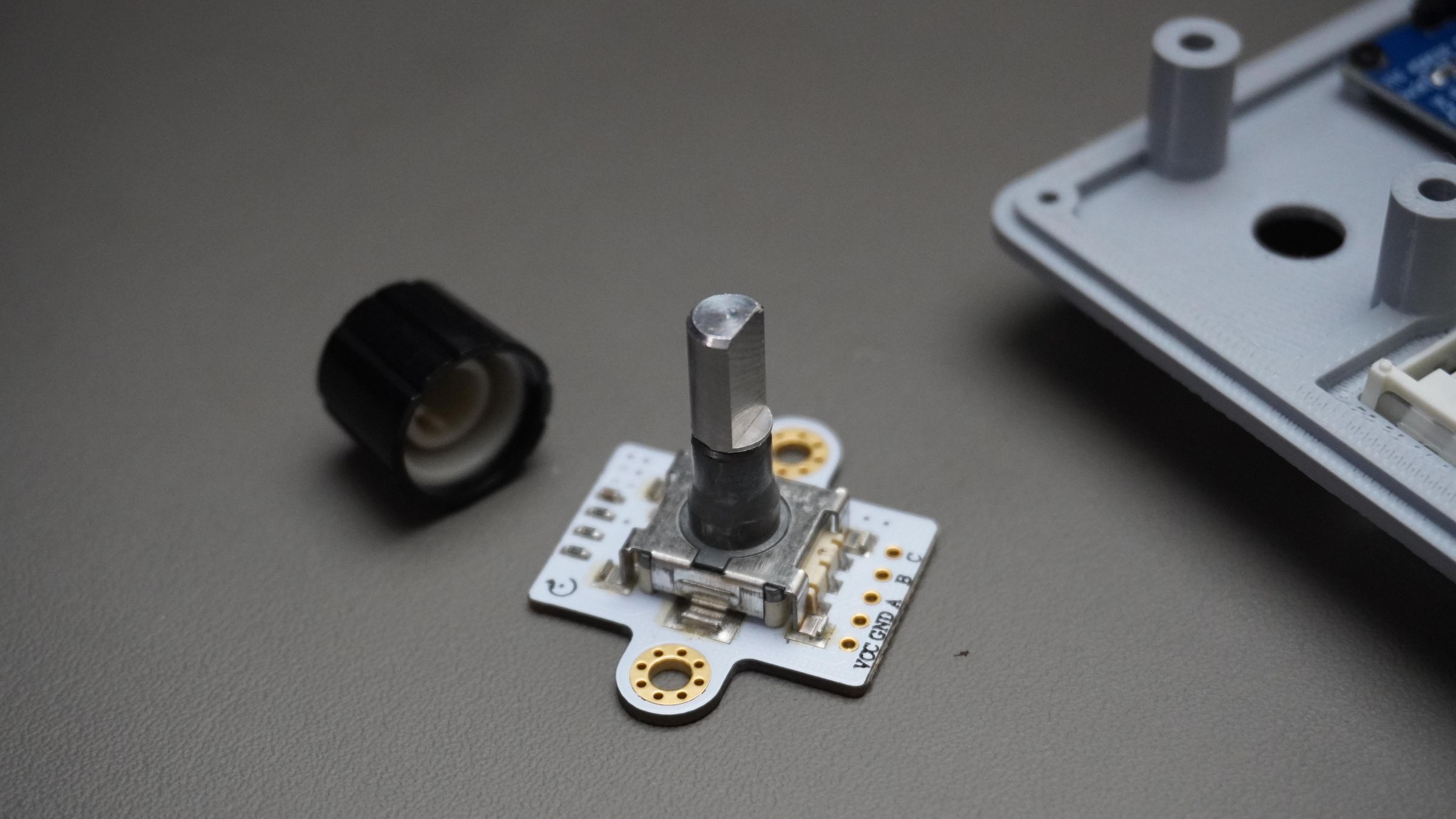
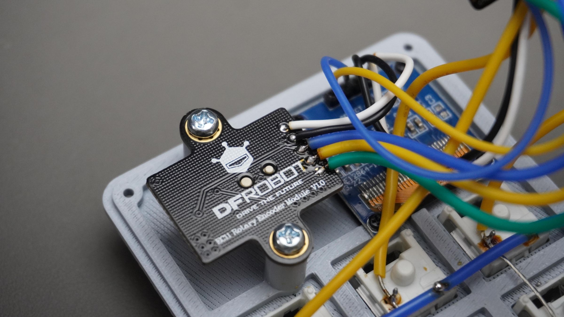
Step 8: Mounting the Encoder
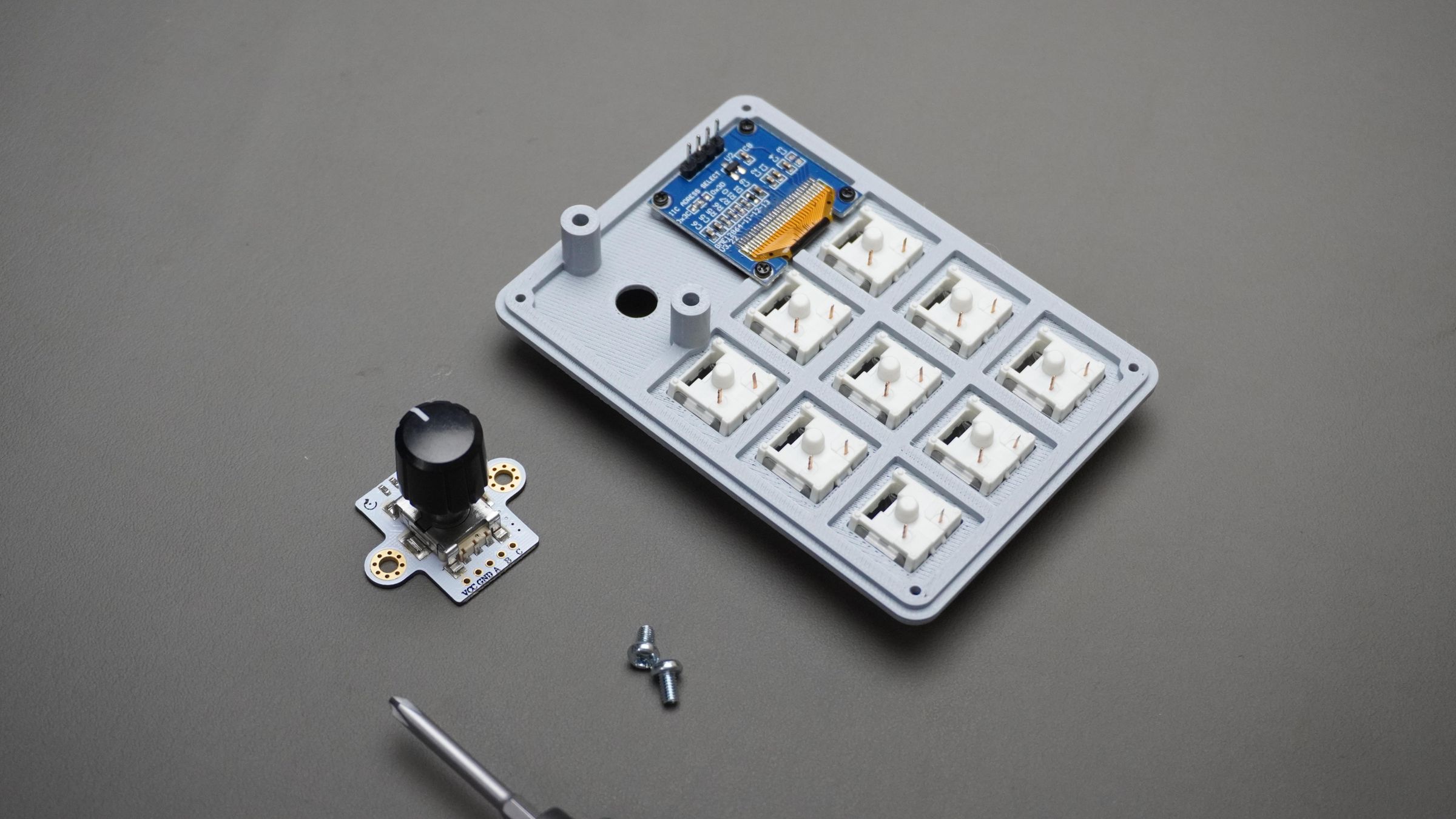
Take:
- The rotary encoder
- 2x M3 × 6mm screws
Place the encoder on the back side of the Top_Cover and align it with the raised mounting holes.
Insert the screws and tighten them until the encoder is firmly secured in place.
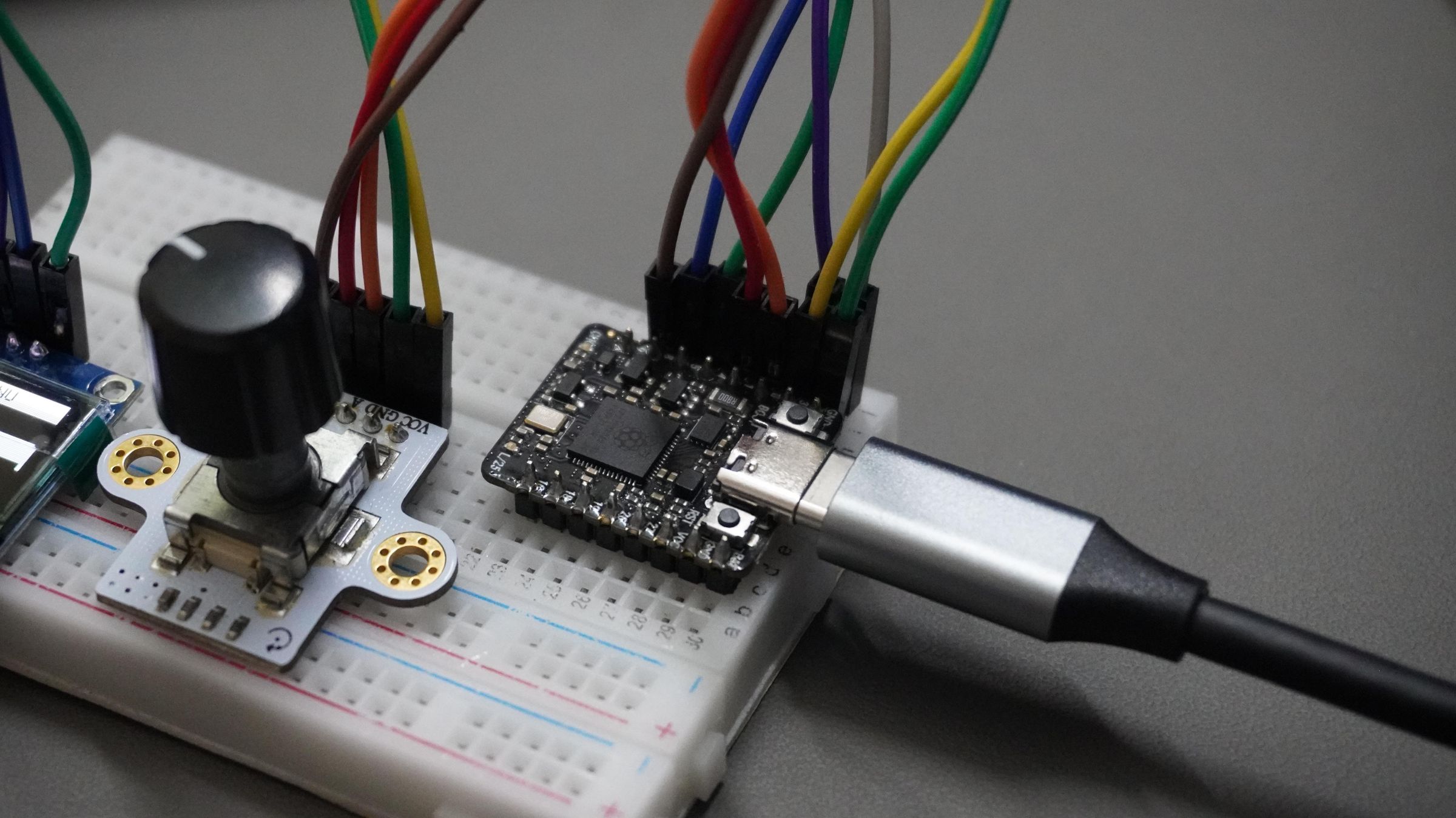
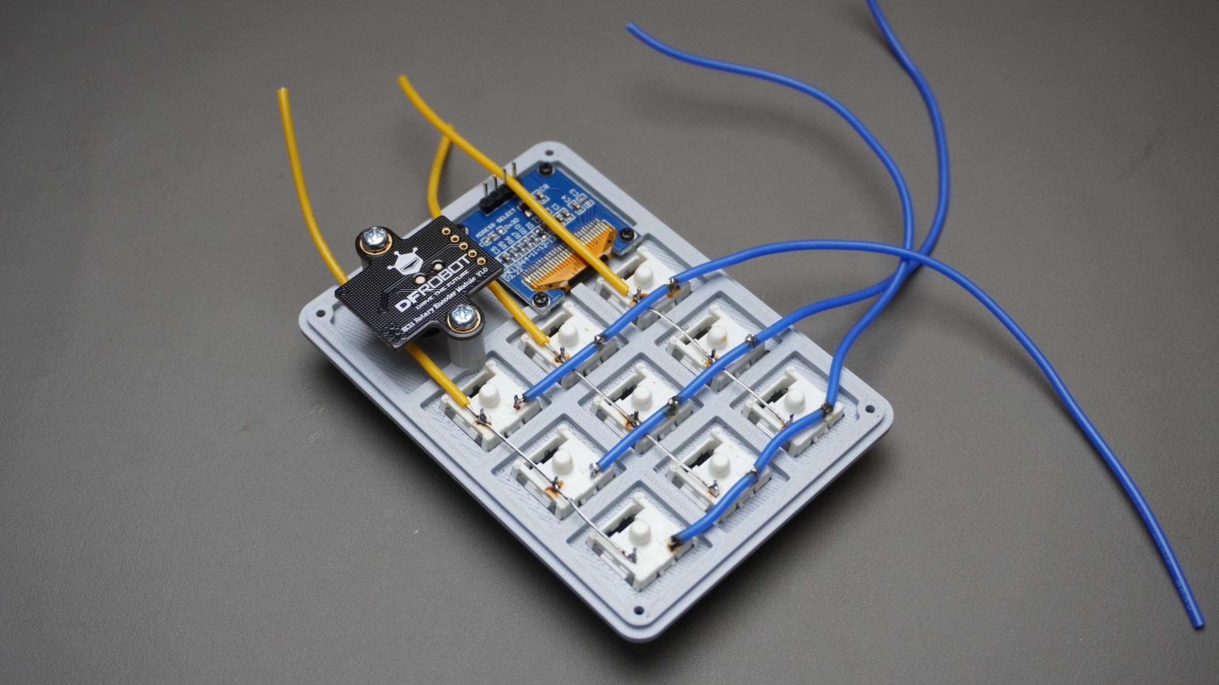
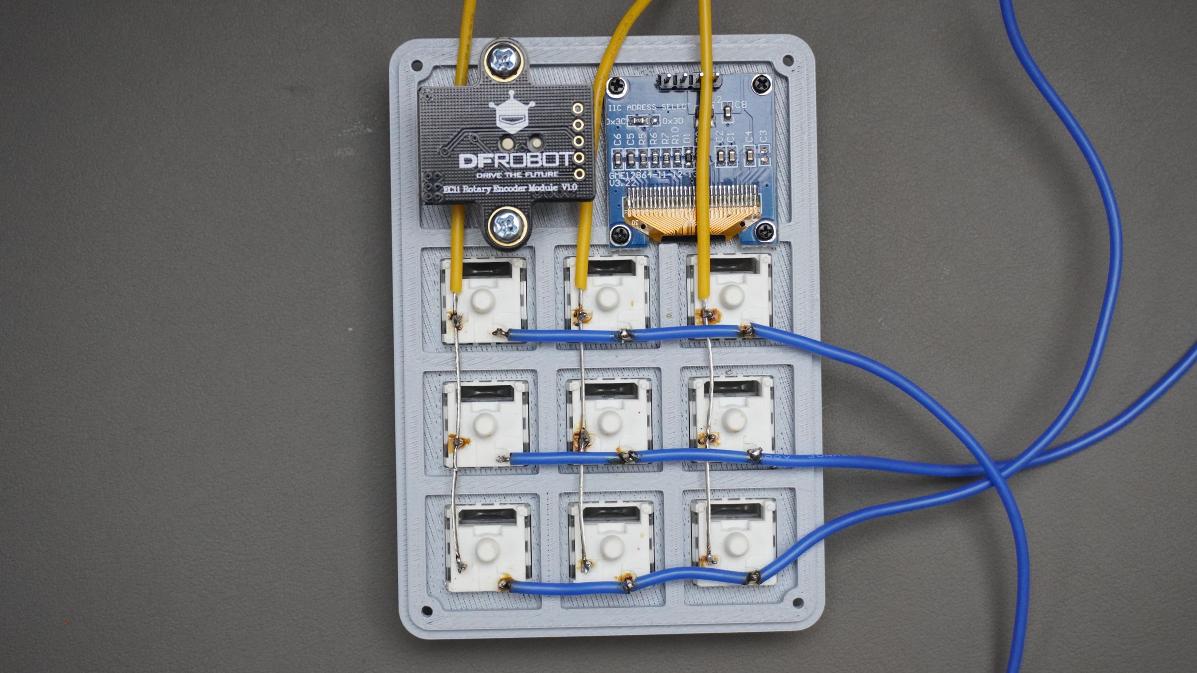
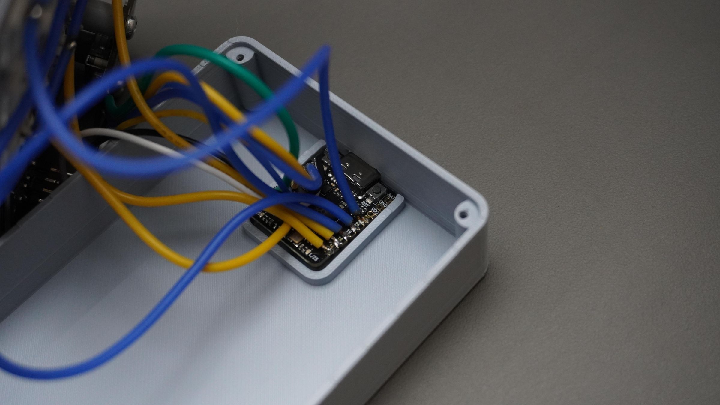
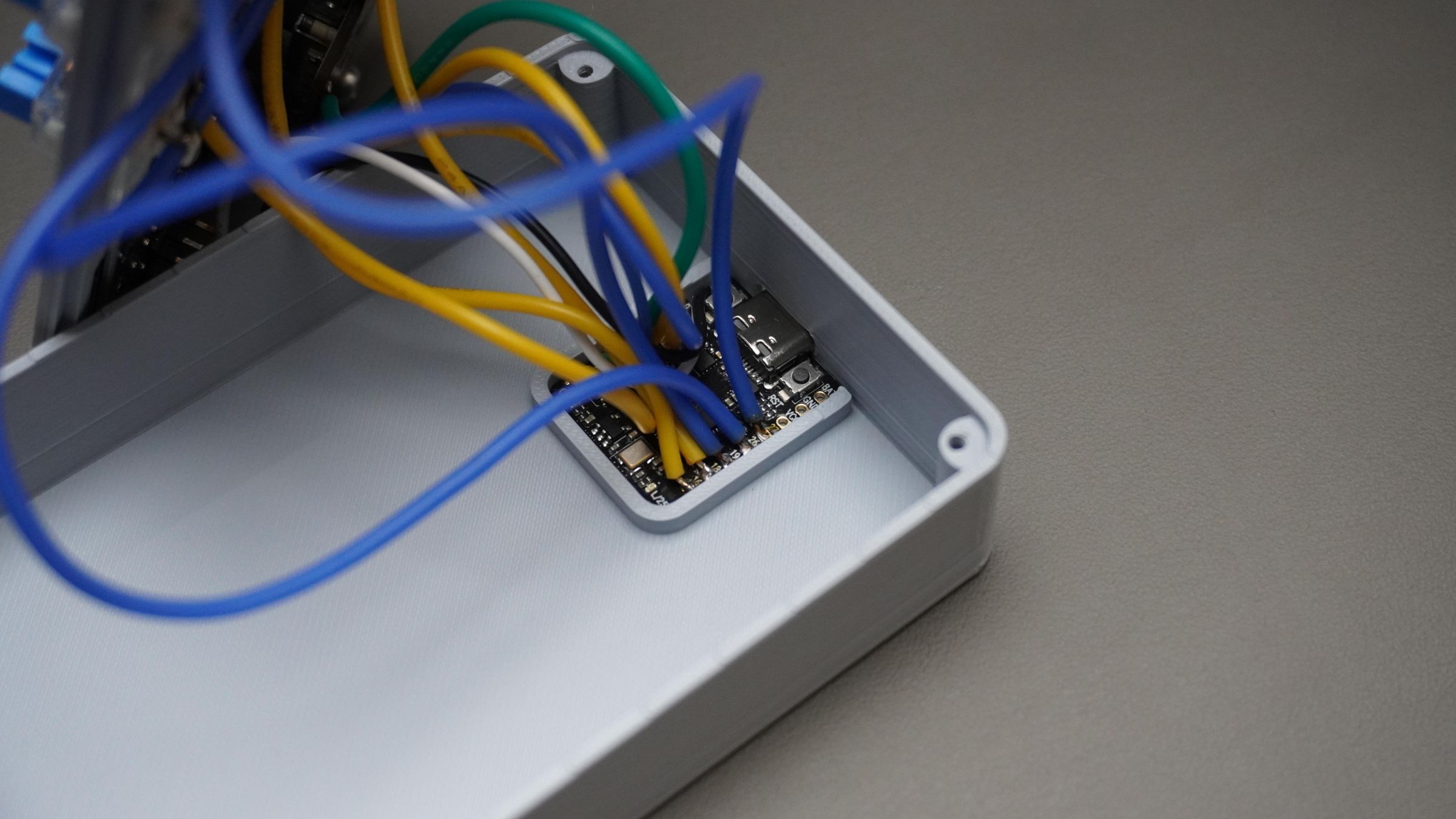
Step 9: Circuit Connections
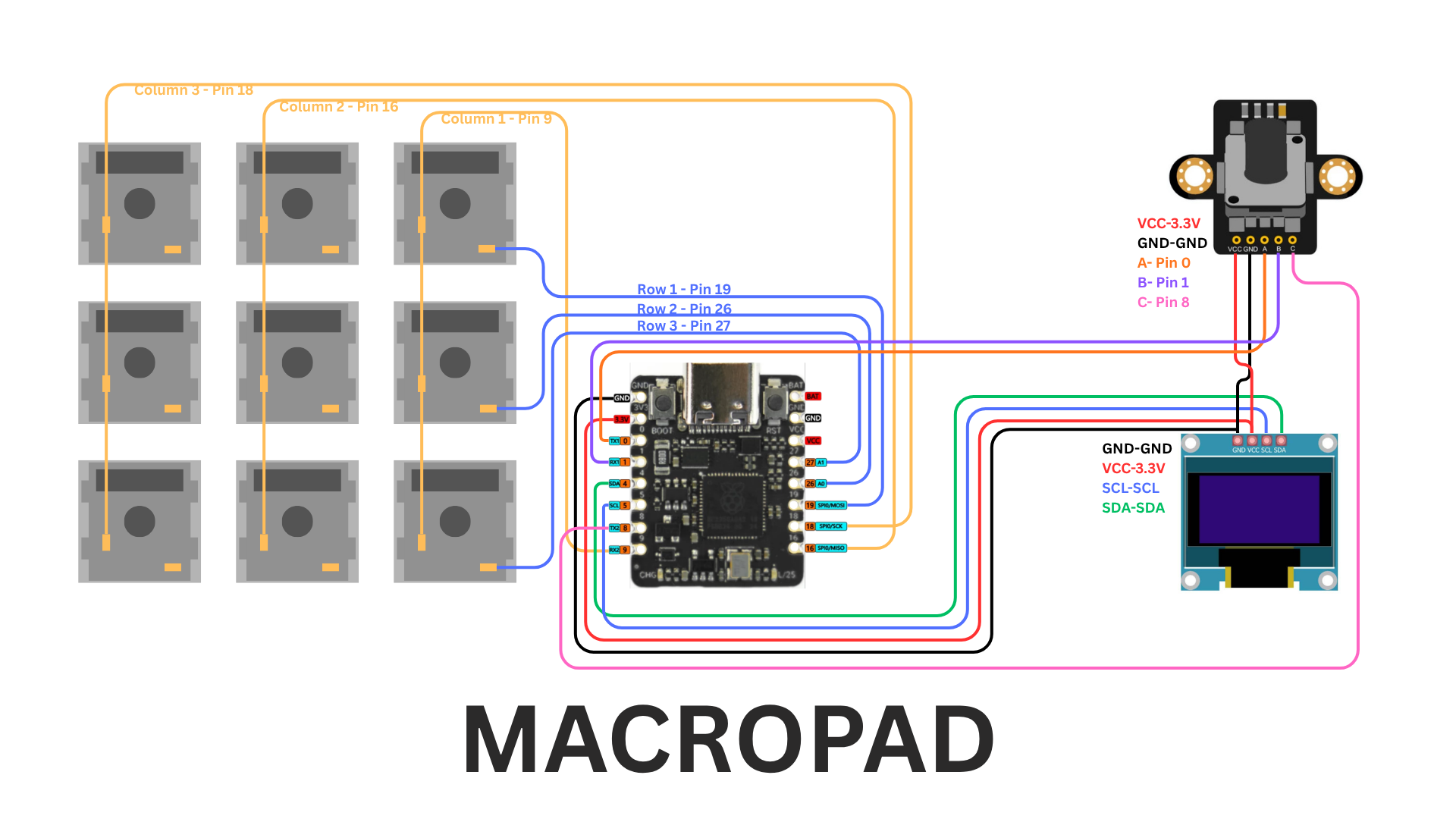
Now connect and solder all the components according to the wiring diagram provided.
This macropad uses a simple hand-wired matrix, so no custom PCB is required. All switches, the OLED display, and the rotary encoder are directly connected to the DFRobot Beetle RP2350.
Switch Matrix:
Columns
- Column 1 → Pin 9
- Column 2 → Pin 16
- Column 3 → Pin 18
Rows
- Row 1 → Pin 19
- Row 2 → Pin 26
- Row 3 → Pin 27
Rotary Encoder:
- VCC → 3.3V
- GND → GND
- A → Pin 0
- B → Pin 1
- Switch (C) → Pin 8
OLED Display (I2C):
- VCC → 3.3V
- GND → GND
- SCL → SCL
- SDA → SDA
Soldering Tips:
- Use thin flexible wires to keep the assembly compact
- Double-check polarity before powering the board
- Test connections with a multimeter if possible
- Keep solder joints small to avoid shorts between switch terminals
Once all connections are complete, the hardware assembly is ready for final installation into the enclosure.
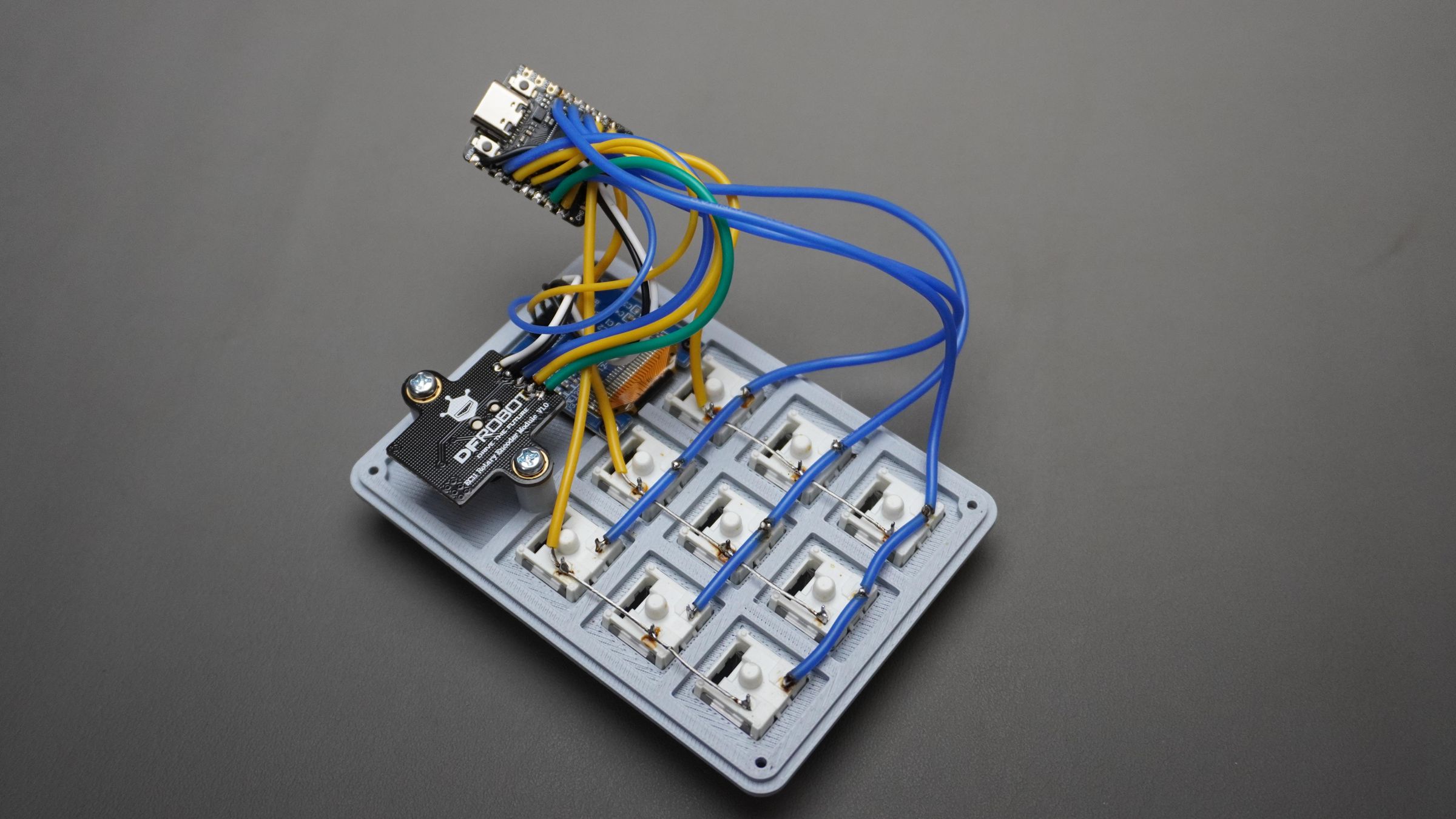
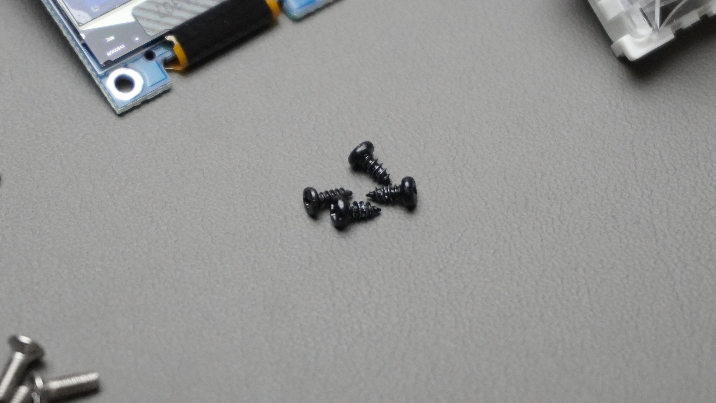
Step 10: Housing Assembly
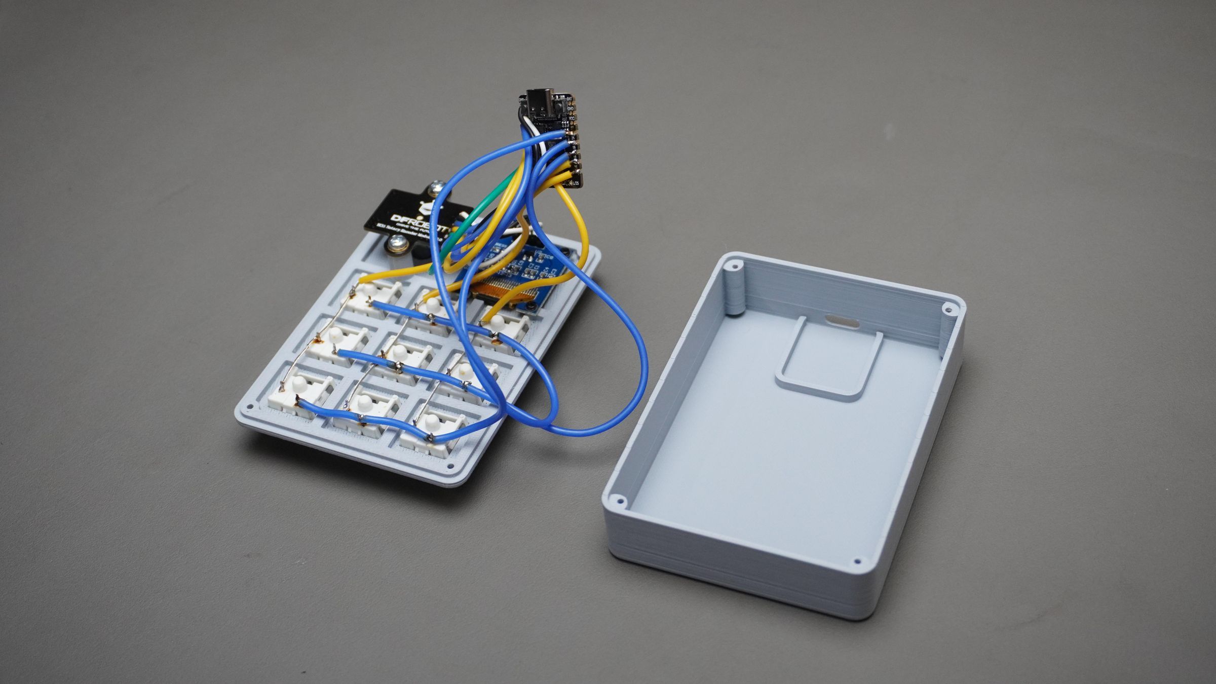
Now take:
- The Housing
- The fully assembled Top_Cover
Carefully place the DFRobot Beetle RP2350 inside the housing and align the USB Type-C port with the cutout provided on the side.
Press the board gently into its slot until it sits securely in place.
Next:
- Align the Top_Cover with the housing
- Make sure no wires are getting pinched inside the enclosure
Use:
- 4x M2 × 6mm screws
to secure the cover to the housing.
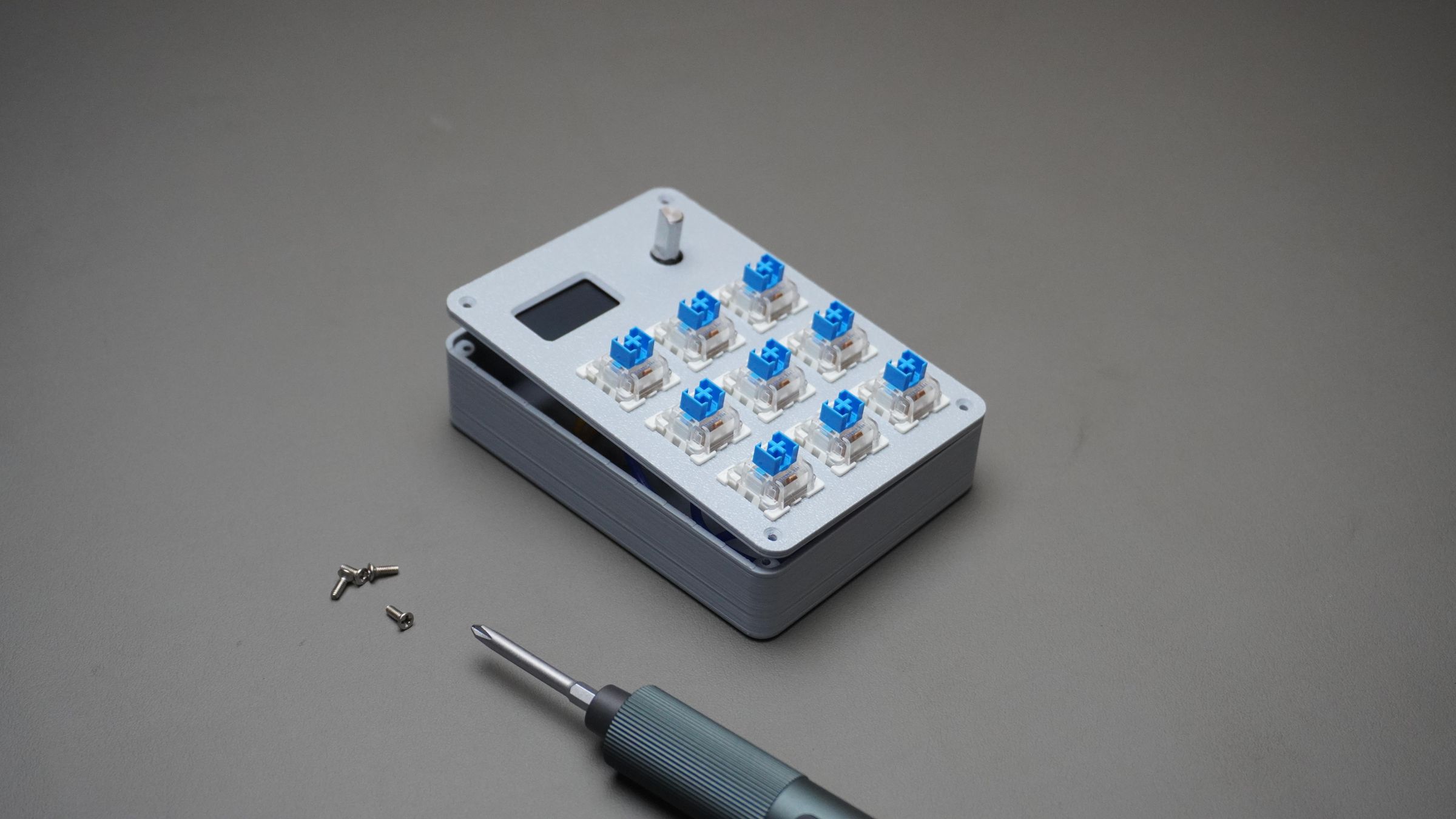
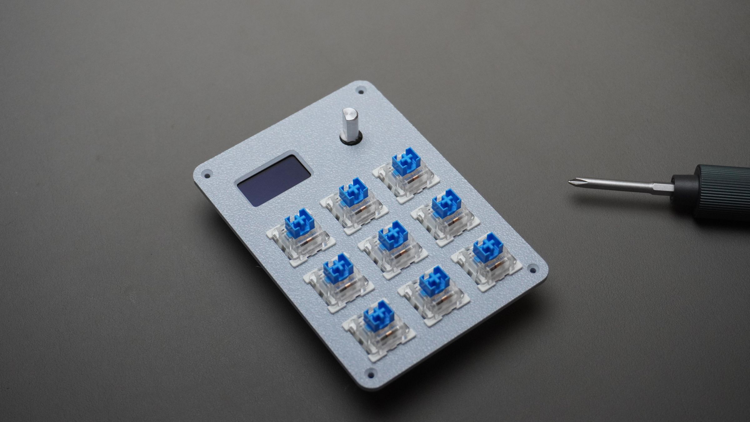
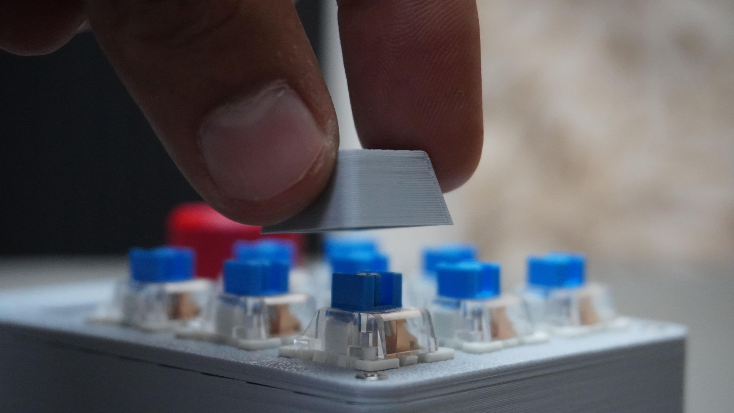
Step 11: Keycaps and Knob Assembly
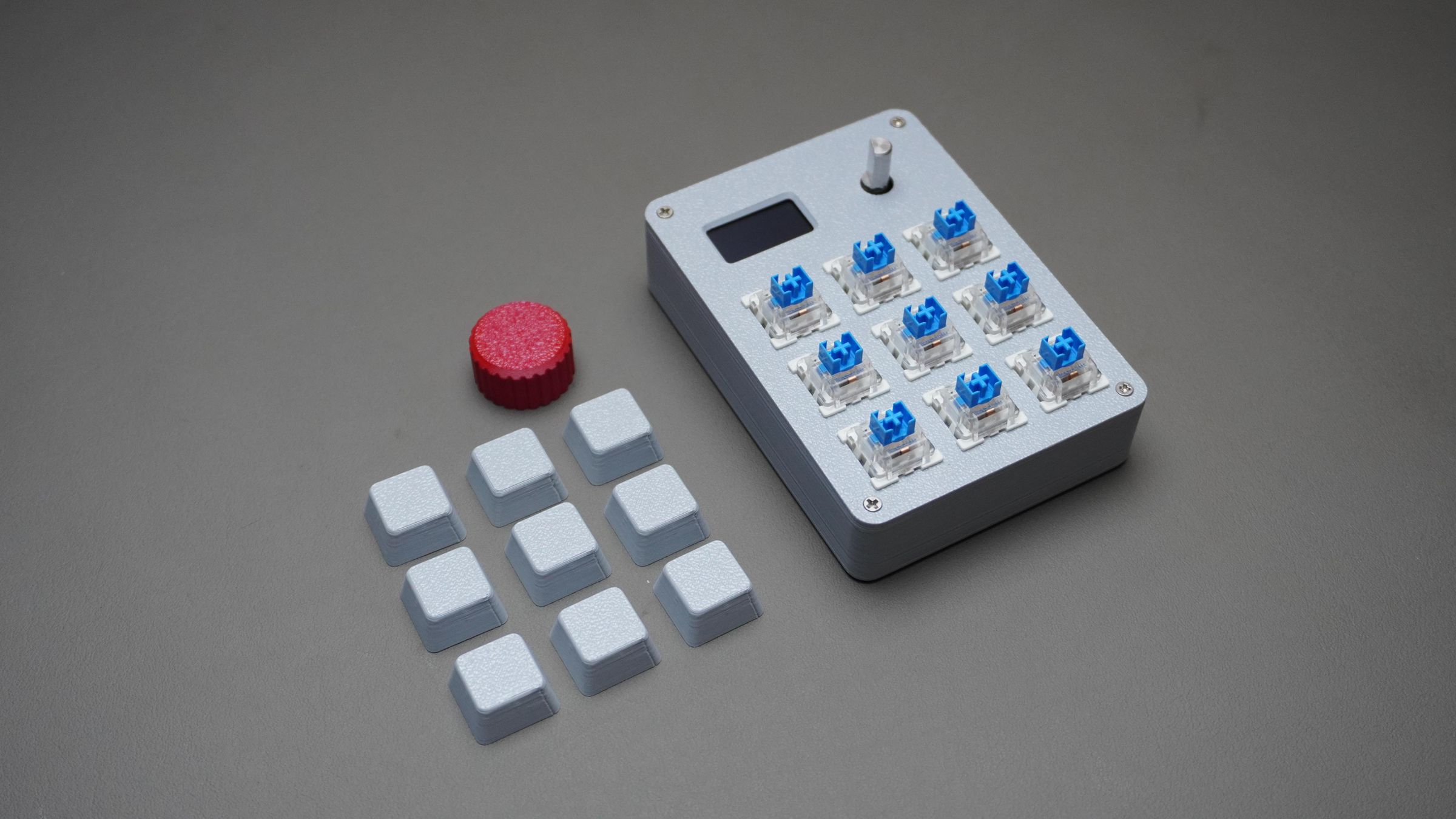
Now take:
- The 9x 3D printed keycaps
- The 3D printed encoder knob
Press each keycap onto the mechanical switches until they fit securely.
Next, align the knob with the rotary encoder shaft and press it into place.
Your macropad is now fully assembled and ready to use.
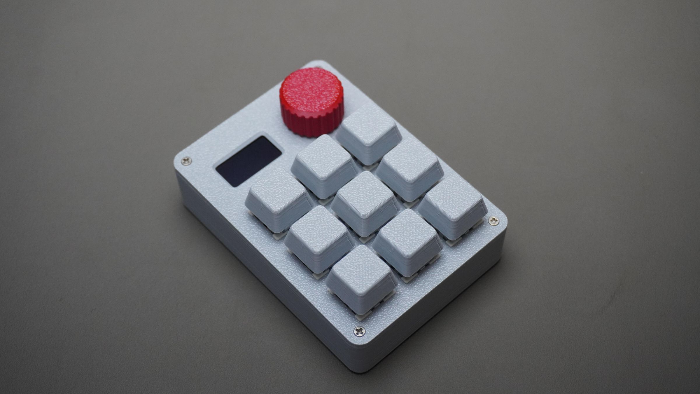
Step 12: How to Use the Macropad
Simply connect the macropad to your PC using a USB Type-C cable.

Once powered on:
- The OLED display shows a boot animation
- The macropad starts in the default Windows Mode
Currently, the firmware includes 5 different modes:
- Windows
- VS Code
- Fusion 360
- DaVinci Resolve
- Media Controls
Switching Between Modes
The rotary encoder is used for navigation.
To open the mode selection menu:
- Press the encoder knob once
To navigate:
- Rotate the encoder to move through the available modes
To select a mode:
- Press the encoder again
Once selected, the OLED updates and displays all key functions in a simple 3×3 layout corresponding to the physical keys.
Quick Media Toggle
Double-pressing the encoder knob enables quick switching between:
- Media Mode
- Your currently selected working mode
This makes it easy to quickly adjust volume or media playback without leaving your active workflow.
Step 13: Customizing the Macropad Using the Web App
To make the macropad easier to configure, I also built a dedicated web-based configuration tool.
Instead of manually editing the code.py file, you can now visually:
- Add new modes
- Edit key mappings
- Configure encoder actions
- Customize OLED labels
- Create shortcuts
- Sync everything directly to the macropad
The interface is designed to look and behave like the physical macropad itself, making customization much more beginner-friendly and intuitive.
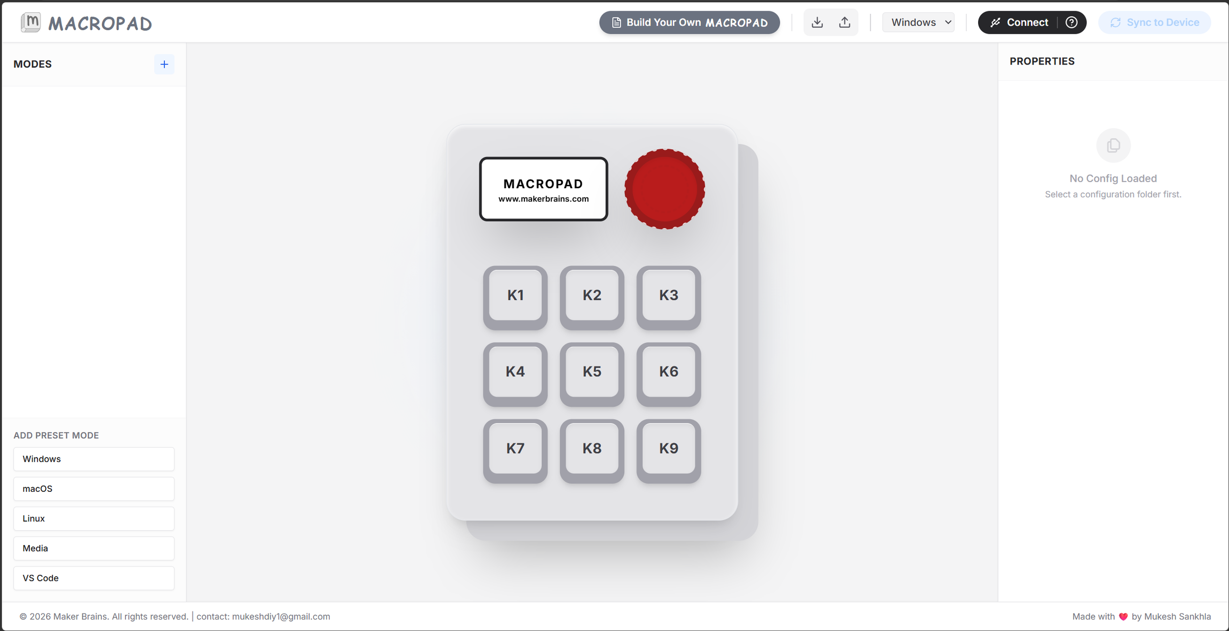
Open the Web App
Open the Macropad UI in your browser: Macropad Web UI
Connect the Macropad
- Connect the macropad to your PC using a USB Type-C cable
- Open the web app
- Click the Connect Device button
- Select the CIRCUITPY drive
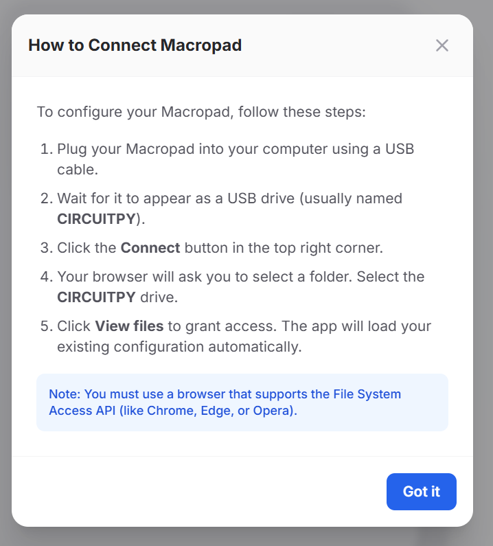
Once connected:
- The app automatically reads the saved mode configuration
- Existing modes appear in the sidebar
- The OLED preview updates live
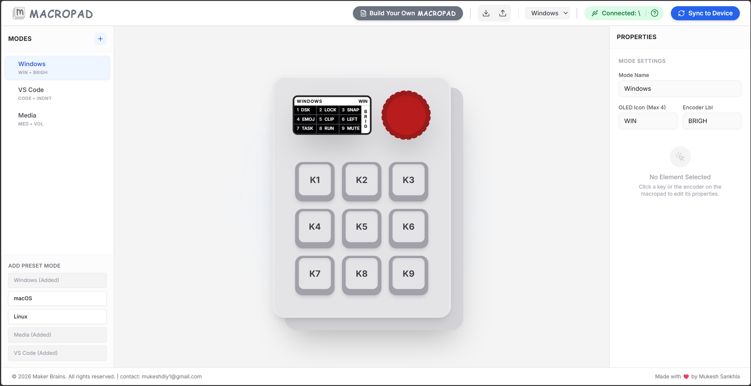
Editing Modes
The left sidebar contains all available modes.
You can:
- Select a mode
- Rename it
- Duplicate it
- Delete it
- Create completely new modes
Example modes:
- Windows
- VS Code
- Fusion 360
- DaVinci Resolve
- Media
The selected mode instantly updates the virtual macropad preview in the center.
Editing Keys
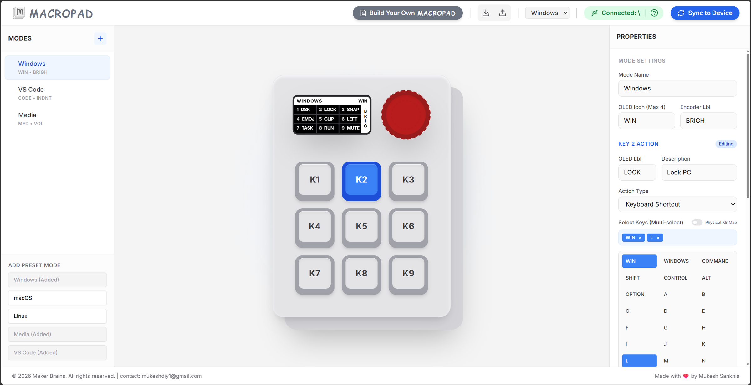
Click any key on the virtual 3×3 keypad to edit it.
For every key, you can configure:
- OLED label
- Description
- Shortcut type
- Multi-key combinations
- Media controls
- Macros
Example:
Label: COPY Shortcut: CTRL + C
The UI also includes a visual keyboard selector, making it easy to create complex shortcuts without memorizing keycodes.
Encoder Configuration
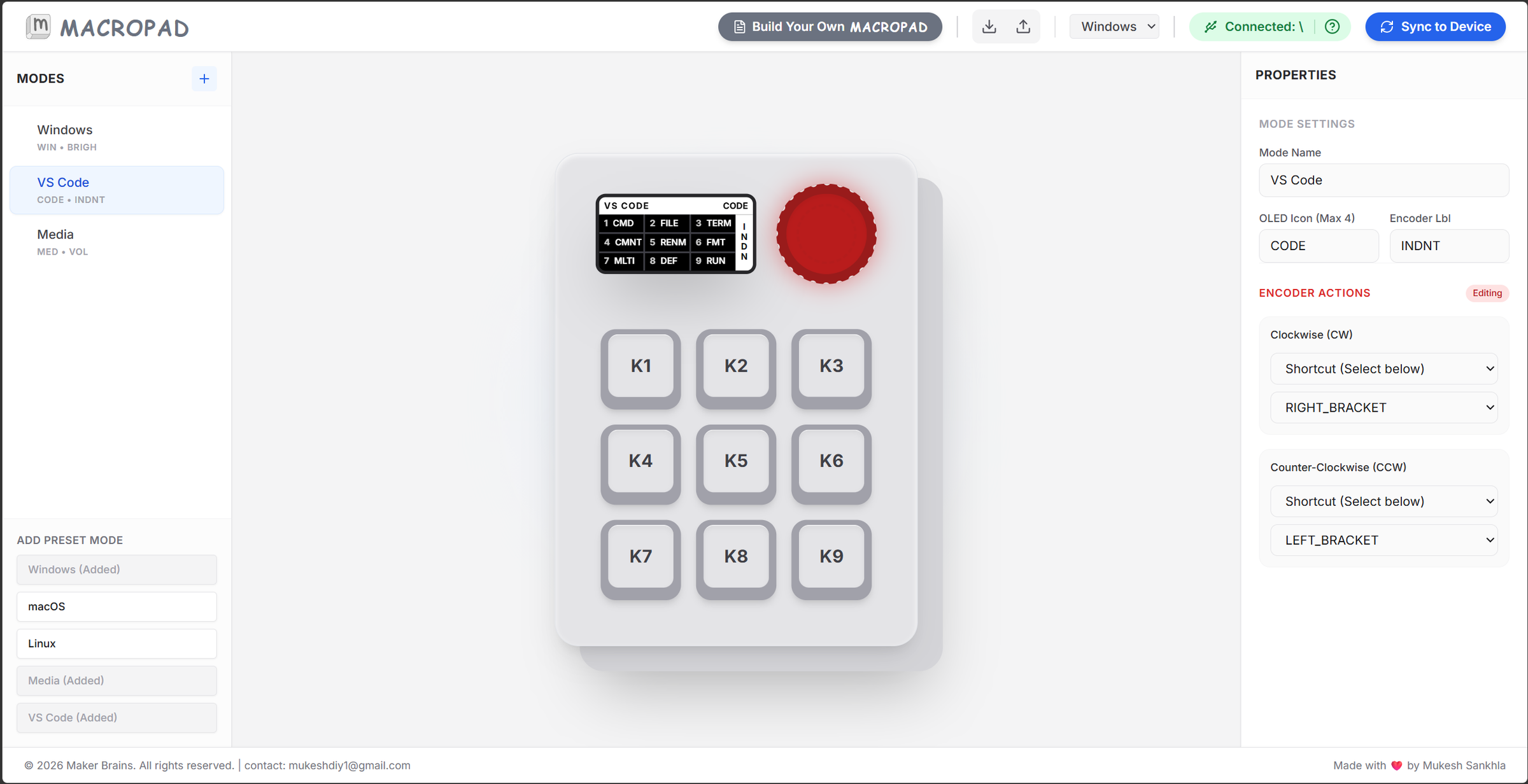
The encoder can also be customized directly from the UI.
You can assign:
- Clockwise rotation
- Counter-clockwise rotation
Example uses:
- Volume control
- Zoom
- Timeline scrubbing
- Brightness control
- Mode switching
The OLED preview updates in real time while editing.
Platform Support
The web app also includes preset profiles and shortcut mappings for:
- Windows
- macOS
- Linux
This makes it easier to use the same macropad across different operating systems without manually rebuilding shortcuts every time.
Import & Export Profiles
The UI supports:
- Profile export
- Profile import
This allows you to:
- Back up your configuration
- Share profiles with others
- Load different workflow setups instantly
For example, you can maintain separate profiles for:
- Coding
- Video editing
- CAD work
- Streaming
- Productivity
Syncing to Device
Once finished:
- Click Sync to Device
- The app automatically updates the macropad configuration
- The device reloads with the new settings
The web app generates and updates a modes.py configuration file stored directly inside the CircuitPython filesystem.
This means:
- No firmware reflashing required
- No manual coding required
- Easy future customization
The goal of this software was to make custom hardware feel much more accessible, visual, and beginner-friendly while still keeping the flexibility of an open maker project.
Step 14: Conclusion
This project started as a simple idea for a custom macropad, but it gradually evolved into a complete ecosystem combining hardware design, embedded programming, 3D printing, and user-focused software tools.
By avoiding a custom PCB and using snap-fit 3D printed parts, the macropad becomes easier to build, modify, repair, and customize using commonly available components. The modular approach also encourages experimentation and learning, especially for makers who want to explore electronics and product design without expensive manufacturing processes.
What makes this project especially exciting is the software side. Alongside the hardware, I also designed a web-based configuration interface that allows users to visually create modes, remap keys, customize encoder actions, and sync settings directly to the device. This transforms the macropad from a fixed hardware tool into a highly flexible productivity platform tailored to individual workflows.
For me, this project represents a small step toward a better future where technology is:
- More open
- Easier to repair
- More customizable
- More approachable for learning and creativity
I hope this project inspires others to build their own tools, experiment with custom hardware, and explore how maker-driven design can create more accessible and user-friendly technology.


