

In this lesson, you'll understand how the LM35 temperature sensor works and build a cool project with it.

Things used in this project
Software apps and online services
Arduino IDE
Story
I've recently posted a tutorial about this project on YouTube explaining everything you can read on this article. You can watch it right below.
Introduction
What if your Arduino could feel temperature the same way your skin does - and react to it?
With a tiny sensor like the LM35, that's exactly what we can do. This small integrated circuit measures the temperature around it and converts it into a voltage that Arduino can read.
In this lesson, you'll understand how this sensor works and build a project that reads room temperature and displays it in a smart, interactive way.
Welcome to lesson 17 of our 24-part series called Arduino for Beginners.
Explanation
Let's begin by understanding what the LM35 actually is.
The LM35 is a precision analog temperature sensor IC. Unlike thermistors, it does not measure temperature through resistance changes.
Instead, it contains internal circuitry that outputs a voltage directly proportional to temperature. This makes it very convenient for use with microcontrollers such as Arduino.

The sensor can measure temperatures from about -55°C up to 150°C. That range is more than enough for most hobby, educational, and indoor environment projects.
The key characteristic of the LM35 is its scale factor. For every increase of 1°C, the output voltage increases by 10 millivolts (10 mV).
This linear behavior is a huge advantage. We don't need complex equations or lookup tables. A simple multiplication is enough to convert voltage into temperature.
Another major benefit is that the LM35 does not require calibration in normal use. Calibration is performed during manufacturing at the wafer level.
According to the datasheet, typical accuracy is around ±0.25°C at room temperature and about ±0.75°C across the full temperature range. That level of precision is excellent for such a simple component.

The module we are using is very straightforward. It has three connections:
• VCC for power
• GND
• Signal pin that outputs an analog voltage.
Because the output is analog, we will connect it to one of Arduino's analog input pins.
That's enough theory. Let's build something practical.
Sponsor

Before moving on, you might be wondering where to get components like this. The LM35 used in this project was kindly provided by the sponsor of this series: DFRobot.
DFRobot is a global provider of hardware for makers, students, and engineers. In their store, you can find sensors, modules, boards, and kits such as the MindPlus Arduino Coding Kit, which we've been using throughout this course.


This kit includes a wide range of components, making it ideal for beginners who want to follow along and build every project in the series. You can find the link to their store in the description.
Thanks to DFRobot for supporting this series and helping make STEM education more accessible to everyone.
Now let's continue with the build.
Project
Today's project is simple but very powerful.
We will measure room temperature with the LM35 and display it on an I2C LCD screen. To make the system more interactive, we'll also add a push button.
The system starts by showing temperature in Celsius. When you press the button, the display switches to Fahrenheit. Press again, and it goes back to Celsius. This gives the project a more professional and user-friendly interface.
To build it, you will need:
Arduino UNO
I/O expansion shield
LM35 sensor
Push button module
I2C LCD module
Some jumper wires


Start by attaching the I/O expansion shield to the Arduino board.
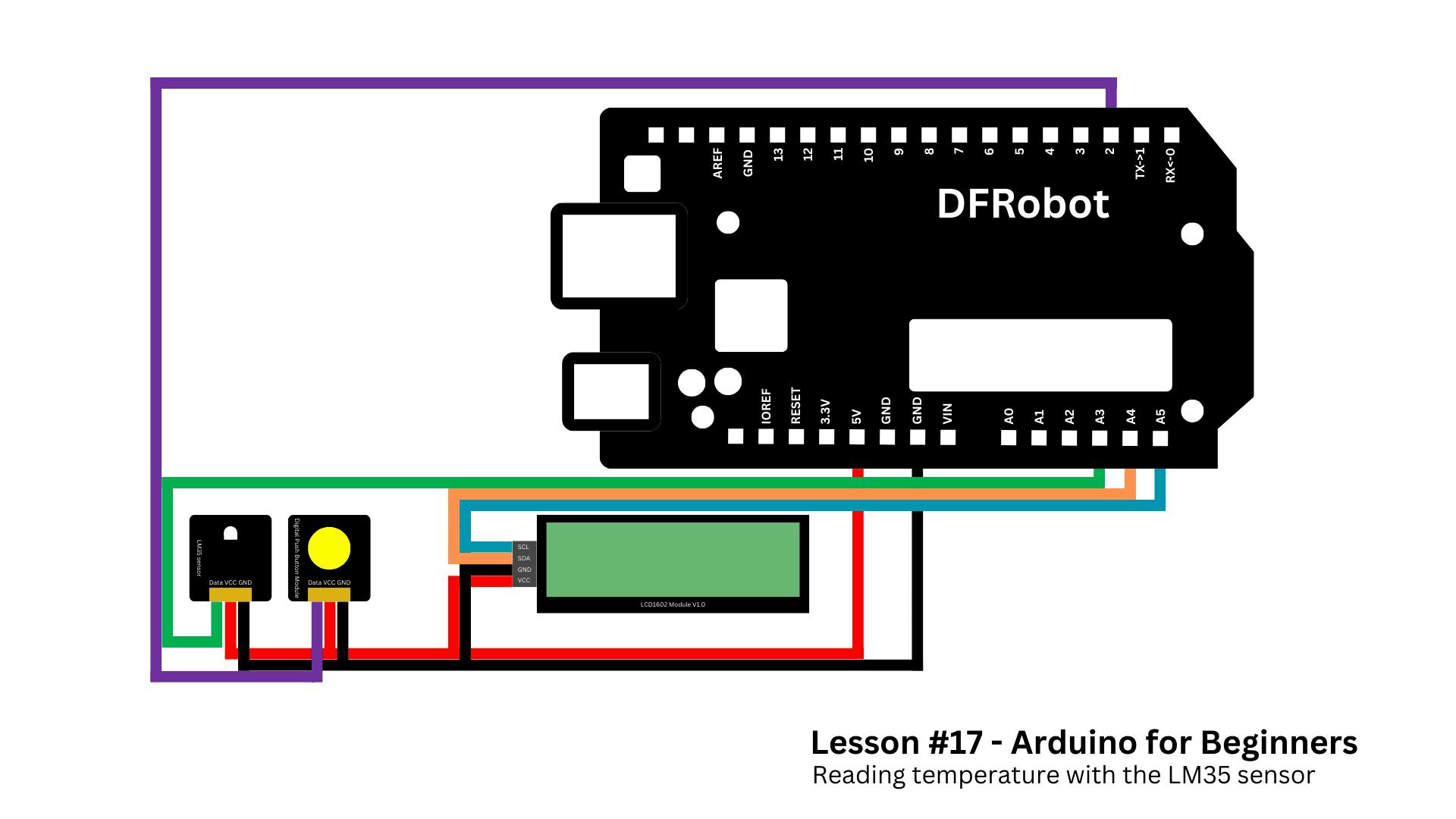
Connect the push button to digital port 2.
Connect the LM35 signal pin to analog port A3, and make sure its VCC and GND are connected properly.
For the LCD module, connect SCL to A5, SDA to A4, VCC to VCC, and GND to GND.
If you need additional help, follow the schematic below.


Next, open the GitHub repository for this course, go to the folder for lesson 17, and copy the file called read_temperature.ino
Paste it into the Arduino IDE. Before uploading, make sure the DFRobot_RGBLCD1602 library is installed.
Upload the code and observe the system.


The LCD shows temperature in Celsius. Press the button, and it switches to Fahrenheit. Press again, and it returns to Celsius. Simple behavior, but very effective.
Now let's understand how the code works.
Code


At the top of the sketch, we include the required libraries and define the pins and main variables. We also create the LCD object that allows us to communicate with the display.
#include <Wire.h>
#include <DFRobot_RGBLCD1602.h>

#define LM35_PIN A3
#define BUTTON_PIN 2

DFRobot_RGBLCD1602 lcd(0x60, 16, 2);

bool showCelsius = true;

bool lastReading;
bool buttonState;
unsigned long lastDebounceTime = 0;
const unsigned long debounceDelay = 50;

unsigned long startTime;

const int numSamples = 10;
int samples[numSamples];
int sampleIndex = 0;
long total = 0;
float smoothedTempC = 0;

unsigned long lastSampleTime = 0;
const unsigned long sampleInterval = 10;
Inside setup(), we start Serial Communication and configure the button pin as INPUT_PULLUP. We initialize the LCD, store the initial button state, and save the start time using millis().
Then we initialize the sample buffer. We take multiple readings from the LM35 and store them in an array, while also computing their total. This allows the averaging system to begin with real data instead of zeros.
void setup() {
  Serial.begin(9600);
  pinMode(BUTTON_PIN, INPUT_PULLUP);

  lcd.init();
  lcd.display();
  lcd.setColorWhite();
  lcd.clear();

  showCelsius = true;
  lastReading = digitalRead(BUTTON_PIN);
  buttonState = lastReading;
  startTime = millis();

  for (int i = 0; i < numSamples; i++) {
    samples[i] = analogRead(LM35_PIN);
    total += samples[i];
  }
}
In the loop() function, we avoid using delay(). Instead, we rely on millis() to control timing. This is a professional programming habit that allows the system to handle multiple tasks without freezing.
Every 10 milliseconds, the program updates the temperature samples. It removes the oldest sample from the total, reads a new value from the LM35, adds it to the total, and advances the index in the array.
The modulo operator makes the index wrap around to the beginning. This structure is called a circular buffer and allows continuous rolling averages.
void loop() {
  unsigned long now = millis();

  if (now - lastSampleTime >= sampleInterval) {
    lastSampleTime = now;

    total -= samples[sampleIndex];
    samples[sampleIndex] = analogRead(LM35_PIN);
    total += samples[sampleIndex];

    sampleIndex = (sampleIndex + 1) % numSamples;
We then compute the average reading, convert it to voltage, and finally to temperature. Since the LM35 outputs 10 mV per °C, multiplying the voltage by 100 gives temperature in Celsius. Fahrenheit is calculated from Celsius using the standard formula.
This averaging process reduces noise and provides more stable readings.
float avgReading = total / (float)numSamples;
    float voltage = avgReading * (5.0 / 1023.0);
    smoothedTempC = voltage * 100.0;
  }

  float tempF = (smoothedTempC * 9.0 / 5.0) + 32.0;
Next comes the button logic. The button is ignored during the first second after startup to avoid false triggers. After that, each button reading is compared with the previous one.
If a change is detected, a debounce timer starts. Only if the state remains stable for more than 50 milliseconds do we accept it as a real press.
When a stable LOW state is detected, which indicates a press because we use INPUT_PULLUP, the variable showCelsius is toggled. This ensures that each press changes the unit only once.
if (now - startTime > 1000) {
    bool reading = digitalRead(BUTTON_PIN);

    if (reading != lastReading) {
      lastDebounceTime = now;
    }

    if ((now - lastDebounceTime) > debounceDelay) {
      if (reading != buttonState) {
        buttonState = reading;
        if (buttonState == LOW) {
          showCelsius = !showCelsius;
        }
      }
    }
    lastReading = reading;
  }
Finally, the LCD is updated every 500 milliseconds. A static variable stores the last update time. Static means the variable keeps its value between loop cycles.
The display is cleared, "Temp:" is printed, and then either Celsius or Fahrenheit is shown along with the degree symbol. Serial printing is included for debugging.
static unsigned long lastLCDUpdate = 0;
  if (now - lastLCDUpdate >= 500) {
    lastLCDUpdate = now;

    lcd.setCursor(0, 0);
    lcd.print("                ");
    lcd.setCursor(0, 0);
    lcd.print("Temp: ");

    if (showCelsius) {
      lcd.print(smoothedTempC, 1);
      lcd.print((char)223);
      lcd.print("C");
    } else {
      lcd.print(tempF, 1);
      lcd.print((char)223);
      lcd.print("F");
    }

    Serial.print("Temp: ");
    Serial.print(smoothedTempC);
    Serial.print(" C | ");
    Serial.print(tempF);
    Serial.println(" F");
  }
}
With this single sketch, you are applying:
Sensor filtering
Non-blocking timing
Circular buffers
Debounce logic
State control
These are all techniques used in professional embedded systems.
Conclusion
That's the end of this lesson.
You didn't just read a temperature value - you built a smarter system that filters data, handles user input correctly, and manages multiple tasks at the same time.


If you enjoyed this project, follow the series so you don't miss the next lesson.
Before the next lesson comes out, I recommend you read this article. I'm sure it'll help you improve your maker skills.
Thanks for reading, and I'll see you in the next one.
Schematics
Code
https://github.com/lucasfernandoprojects/arduino-for-beginners-course
Disclaimer: This article is reproduced from the original project by Lucas Fernando on Hackster.io. All credit goes to the original author.
Original: https://www.hackster.io/lucasfernando/lm35-temperature-sensor-with-arduino-lesson-17-79c776#toc-project-3