
We are going to build a simple IoT dog feeder that costs less than $30 and can be controlled remotely via an IoT software!

Things used in this project
Hardware components
Software apps and online services
Hand tools and fabrication machines
Soldering iron (generic)
This is for the WeMos D1 Mini board.
Story
Introduction
Has your dog ever woke you up early in the morning for food? Do you blame yourself for not being able to feed your hungry pet because you are too busy and can’t get home on time? Purchasing a smart dog feeder that allows you to control it through the internet can be quite expensive. So why not design and build your own smart dog feeder with a few inexpensive electronic components? In this article, we are going to build a simple IoT dog (or other friendly creature) feeder that costs less than $30 and can be controlled remotely via an IoT software. By the end of this project, you will learn:
What is a WeMos D1 Mini development board and how to use it How to use the Blynk IoT platform to manage your hardware device How to program the WeMos D1 Mini development board using Arduino IDE How to build an IoT dog feeder
Background Knowledge
WeMos D1 Mini
WeMos D1 Mini is a powerful internet-enabled development board. This small development board uses one of the most popular and cost-effective Wi-Fi microchip ESP8266, making it a perfect choice for any beginner-level internet of things projects.
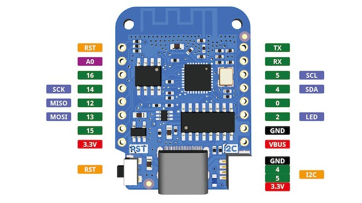
WeMos D1 Mini Pinout
Source: WeMos Documentation
One advantage of the WeMos D1 Mini is that it is user-friendly. It is perfectly compatible with MicroPython, Arduino, and nodemcu. Additionally, WeMos D1 Mini is compatible with the popular Arduino IDE, which allows you to develop and upload programs to the microcontroller.
The WeMos D1 Mini development board has 11 digital I/O pins, a 5V pin and a 3.3V pin. Out of the eleven digital I/O pins, there is one RX pin and one TXpin for serial communication. Every pin on the WeMos D1 mini board runs on 3.3V, anything higher than 3.3V can potentially damage the development board. If you want to use it with 5V devices, you will need a logic level converter.
The WeMos D1 Mini development board can be programmed via USB. Different versions of WeMos D1 Mini development boards have different USB ports. Some have type-C USB ports while others have micro-USB ports. The WeMos D1 Mini board used in this tutorial comes with a micro-USB port.
PIR Motion Sensor
A passive infrared sensor, also known as a Pyroelectric or IR motion sensor, is a small inexpensive sensor that detects motion by measuring the amount of infrared radiation (IR) emitted or reflected by an object within its detection range. The level of infrared radiation detected is dependent on how hot the object is. An object with higher temperature emits more infrared radiation.
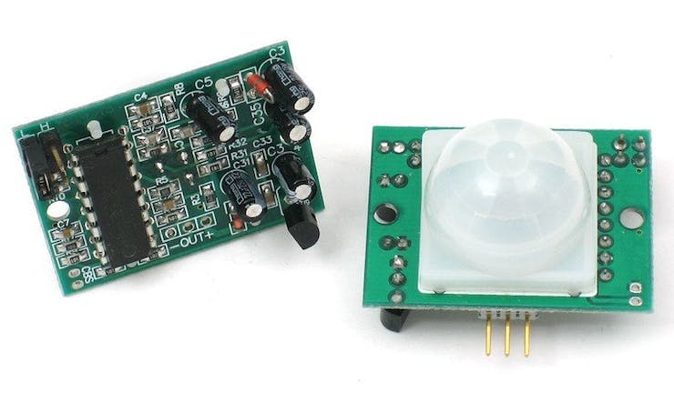
PIR Sensor Image
Source: Adafruit
PIR motion sensors rely on pyroelectric sensors to detect the level of infrared radiation. Pyroelectric sensors are highly sensitive to the change in thermal energy and generate electrical energy when heated or cooled.
The PIR motion sensor is split into two slots. When a living animal passes by the motion sensor, one side will detect the moving object before the other. The difference in the level of infrared radiation between the two sides of the motion sensor creates a positive differential change. When the moving object leaves the detection region, there will be a negative differential change between the two sides of the motion sensor.
Why do different PIR motion sensors have different detection ranges? The answer lies in the spherical lens of the motion sensor. PIR motion detectors use Fresnel lenses to condense a large range of IR to the sensor. In a PIR motion detector, the Fresnel lens is divided into many small sections, each section contains many concentric circles to focus light on a single point. The structure of the Fresnel lens allows the PIR motion sensor to detect motion in a large area.
Steps:
1. Building the Circuit
Let’s first talk about how to use each electronic component and build the circuit for this project.
1.1 Starting the Circuit with the WeMos D1 Mini
WeMos D1 Mini has eleven digital I/O pins, one analog input pin (A0), one 3.3V pin, one 5V pin and a ground pin. The 3.3V pin will be used to power the PIR motion sensor and the 5V pin for the servo motor. The WeMos D1 Mini development board can be programmed and powered via a micro-USB. You can familiarize yourself with the WeMos D1 Mini here [https://diyi0t.com/esp8266-wemos-d1-mini-tutorial/].

WeMos D1 Mini Pinout
Source: WEMOS Documentation
Since the WeMos D1 Mini development board has only one ground pin, we will need to use a breadboard to create more. To do this, define one of the breadboard power rails as the ground by connecting it to the ground pin of the WeMos D1 Mini board. The ground pins of the PIR motion sensor, LED, and servo motor can be connected to any of the holes in this power rail.
1.2 Adding the PIR Motion Sensor
The PIR motion sensor has three header pins: ground (black), signal output (yellow), and VCC (red). The signal output pin of this PIR motion sensor should be connected to one of the digital I/O pins on the WeMos D1 Mini board. The PIR motion sensor used in this tutorial requires a minimum input voltage of 3.0V to operate. Therefore, the VCC pin of the PIR motion sensor should be connected to the 3.3V pin.
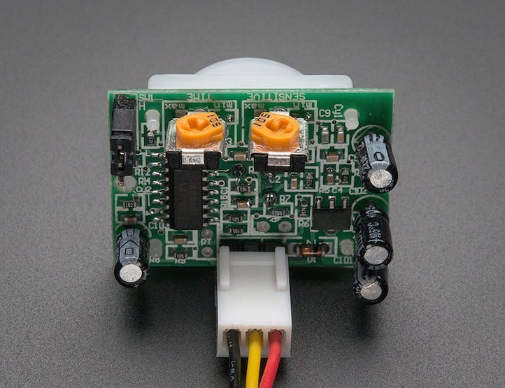
PIR Sensor Pinout
Source: Adafruit
NOTE: PIR motion sensors can be highly sensitive to noise. There have been accounts where the Wi-Fi signals from the WeMos D1 Mini board can create false triggers [https://www.esp8266.com/viewtopic.php?p=94317]. Try to avoid putting your WeMos D1 Mini at a location that is close to the PIR motion sensor if you are having issues with false triggers.
1.3 Adding the Servo Motor
The small servo motor has three wires. The yellow wire is the signal wire and should be connected to a PWM pin on the WeMos D1 Mini board. The red wire is the power wire and should be connected to the 5V pin of the microcontroller. The brown wire is the ground wire and should be connected to the ground pin of the WeMos D1 Mini development board.
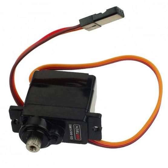
Servo Motor Image and Pinout
Source: Digikey/DFRobot
1.4 Adding Supporting Circuitry (LED and resistor)
In this project, a red LED is used to indicate the state of the PIR motion sensor. The LED will turn on if movement is detected and turn off if there is no movement. The red LED is powered by a digital pin on the WeMos D1 Mini development board.
Calculating the Value of Resistor Needed
Output Voltage of I/O Pin: 3.3 V
Max DC Output Current: 12 mA (Source: https://diyi0t.com/esp8266-wemos-d1-mini-tutorial/)
LED Forward Voltage Drop: 1.7 V - 2 V3.3V - 2V = 1.3V1.3V / (12mA) = 108.333 ohm (Closest standard resistor value = 100 ohm)
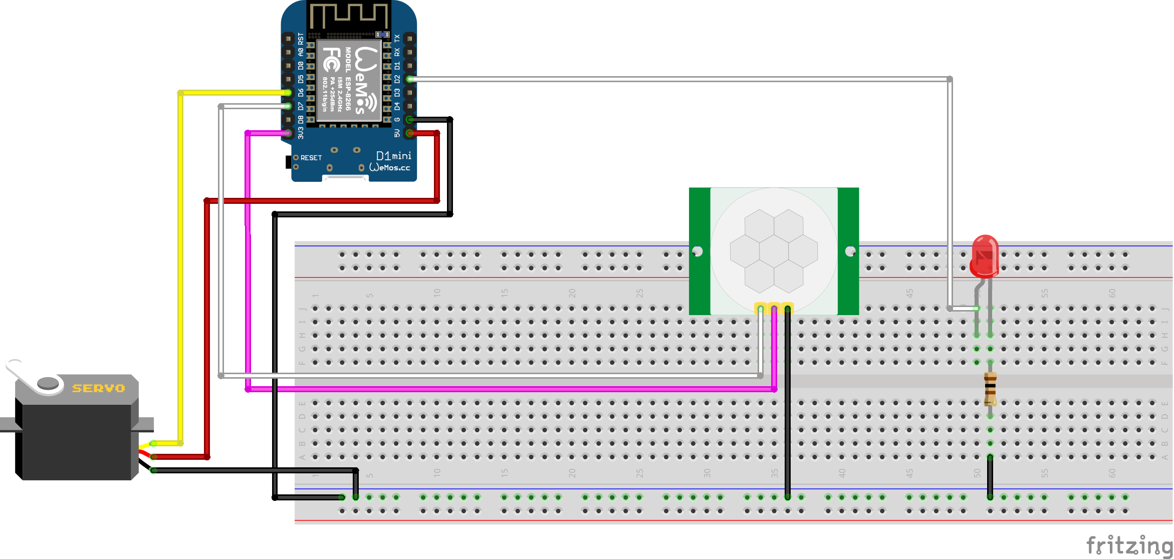
You should end up with a circuit that roughly looks like the following images:
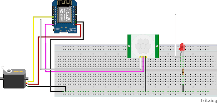
Final Circuit Diagram (Fritzing)
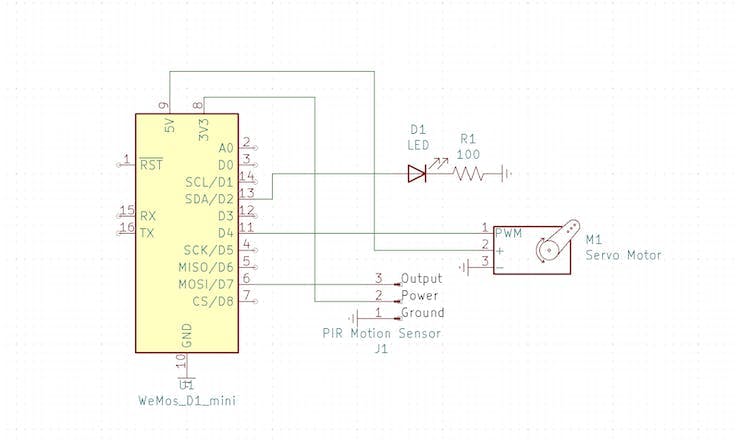
Final Circuit Schematic (KiCAD)
2. Getting Started with the Blynk IoT Platform
Blynk is a very popular IoT platform that helps you manage your IoT applications from your IOS or Android device. This platform allows you to control your Arduino, Raspberry PI and other microcontrollers via the internet. You will be able to complete this project under their free plan. In order to use Blynk, you will need to download the Blynk library in Arduino IDE.
2.1 Installing Blynk Library in Arduino IDE
1. Open Arduino IDE. Go to Tools and select Manage Libraries.2. Type Blynk in the search bar.3. Install the latest version of the library available.
2. Type Blynk in the search bar.
3. Install the latest version of the library available.
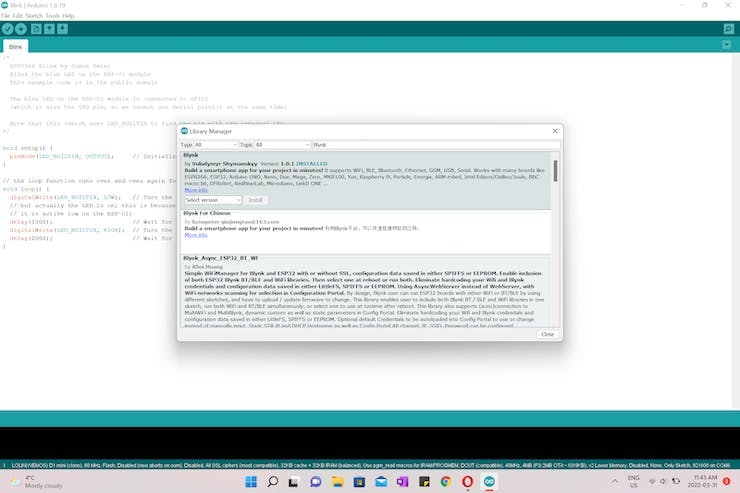
Installing Blynk Library
2.2 Adding ESP8266 Board to Arduino IDE
ESP8266 is not part of the Arduino family so we need to install an add-on in order to program it on Arduino IDE. To use this third-party hardware, we need to install an add-on provided by the ESP8266 community.
1. Go to File and select Preferences.
2. Copy the below URL and paste it into the Additional Board Manager URLs field:
https://arduino.esp8266.com/stable/package_esp8266com_index.json
3. Next, Go to Tools and select Board: and then Boards Manager.
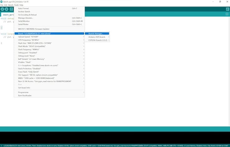
Adding the ESP8266 to Arduino IDE
4. Open Boards Manager and type ESP8266 in the search bar.5. Install esp8266.
5. Install esp8266.
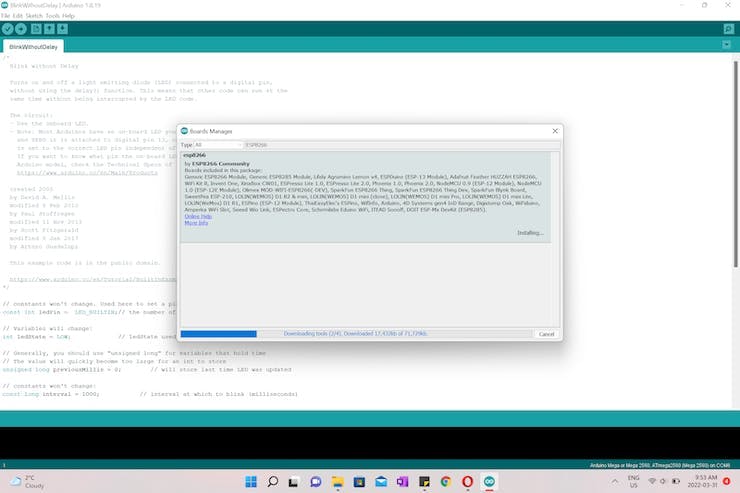
Installing ESP8266 for Arduino IDE
2.3 Managing Your Device on Blynk
After downloading all the required libraries, let’s create a Blynk project to manage our IoT pet feeder.
1. Create a Blynk account and open Blynk in a web browser.
2. Go to Templates and click on the + New Template button at the upper right hand corner of the web page.
3. Name your device and choose the hardware that you will be using. In this project, we will be using ESP8266 and the connection type should be Wi-Fi.
4. Click on the Done button to create a new template.
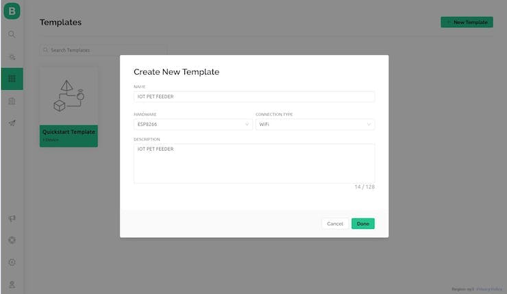
Creating a New Blynk Project
Now that we have created a Blynk project, let’s talk about how to create buttons to control our servo motors using Virtual Pins.
Blynk Virtual Pins are designed to exchange data between the hardware and the Blynk cloud app. Virtual Pins allow you to send commands from the app to the microcontroller or receive data from the microcontroller. With Virtual Pins, you can control a variety of devices such as sensors and servo motors.
2.4 Controlling the Servo Motor using a Virtual Pin
1. Open your hardware device in the Template section.
2. Go to Datastreams and tap on the Edit button at the top right hand corner to start making changes to your project.
3. A datastream is a channel used to exchange data between the hardware device and the Blynk app. To create a channel for data transfer between the hardware and the Blynk app, click on the Add Datastream button and create a new Virtual Pin.
4. Set PIN as V1 and select Integer as the DATA TYPE.
5. Set the MIN and MAX values of the button.
6. After you make all the changes, tap on Save and then the Save and Apply button at the top right hand corner of the webpage.
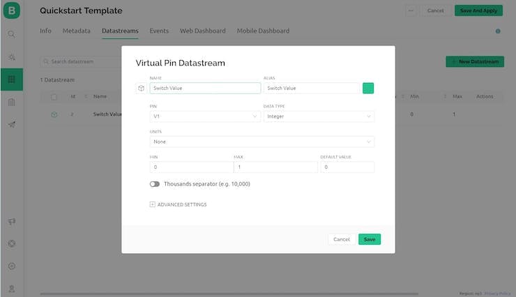
Adding a Virtual Pin Datastream in Blynk
2.5 Creating Notifications on Blynk
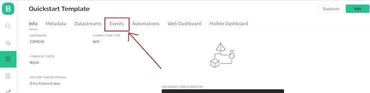
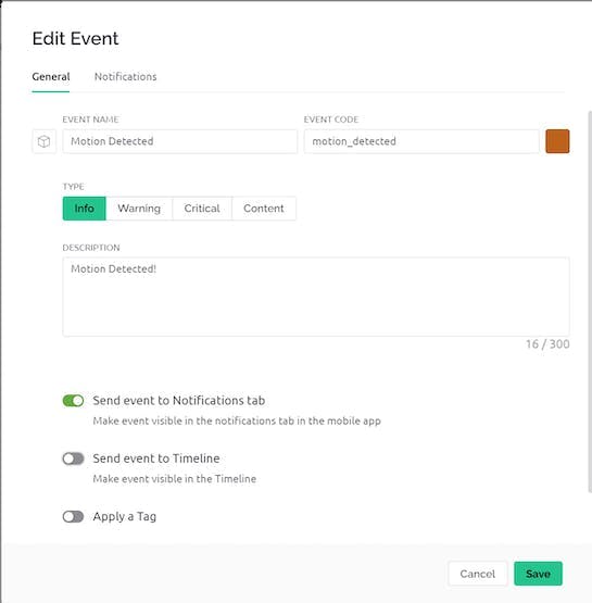
1. In Edit mode, go to Events and tap on + Add New Event.
2. Name your event, and then switch on the option Send event to Notifications tab.
3. Go to Notifications and enable notifications.
4. Blynk offers three ways to deliver notifications: E-mail, Push notifications, and SMS. Add Device Owner under the option you want.
5. Blynk allows you to limit the number of notifications. In the Notifications Limit section, you can limit the number of notifications that can be sent within a specified time period. For example, when the Limit Period is set to 1 hour and Event Counter is set to 1, the user will only receive the notification once within one hour even if the event is triggered many times during the time period.
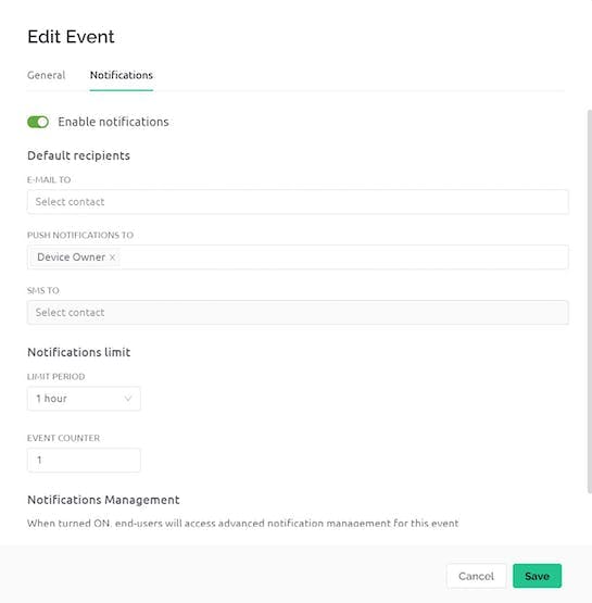
Event Notification Settings in Blynk
6. After you make all the changes, click Save and Apply.
2.6 Downloading Blynk Mobile App and Setting Up Project
After you have configured your Blynk project on the web browser, it is time to set up the project on your mobile device so you can control your hardware remotely.
1. Download Blynk Mobile App from the Apple or Android store.
2. In the Blynk app, open your IoT project and select settings (the wrench at the top right corner).
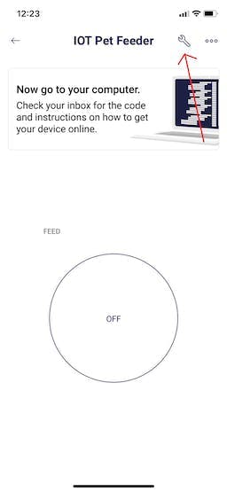
Blynk App View
3. Click on the + button to open the Widget Box.
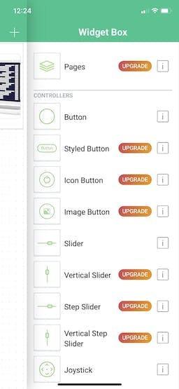
Adding a Blynk App Widget
4. Add the simplest button to your project. This type of buttons can operate in two modes: Push and Switch. When operating in Push mode, the button will switch to ON state when you press it and return to OFF state if you release the button. Switch mode allows you to press the button once and then it will stay on or off until you press the button again to change its state.
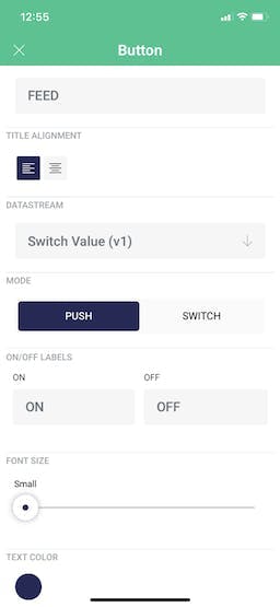
Creating a Blynk App Button
3. Programming the WeMos D1 Mini Microcontroller
You can follow along with this tutorial and write the code as go or simply download the project code here.
3.1 Blynk Library and Settings
At the very top of your main firmware, define Template ID and Device Name before adding any #include directives. The template ID and device name can be found on the Info page of your Blynk device.
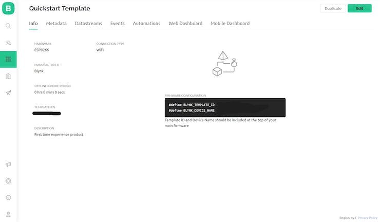
Blynk Info Page
In this project, we are working with the Blynk library, so we need to include the directive #include at the top of the firmware.
Then, we need to configure the network connection in our firmware. We will need to define three parameters. The first one is your Blynk authentication token and it can be found on your Blynk project dashboard. The second one is your Wi-Fi SSID, and the last one is your Wi-Fi password. Once you define the three parameters, include them in the function Blynk.begin(auth, ssid, pass).
Lastly, to complete the Blynk library setup you’ll need to include a #define for the BLYNK_TEMPLATE_ID and BLYNK_DEVICE_NAME parameters that should also be found on your Blynk project dashboard.
#define BLYNK_TEMPLATE_ID "Replace with your template ID"
#define BLYNK_DEVICE_NAME "Quickstart Template"
#include <BlynkSimpleEsp8266.h>
// ESP8266
char auth[] = "Your Blynk Auth Token"; // Blynk token
char ssid[] = "Replace with your WiFi SSID"; // Your WiFI SSID
char pass[] = "Replace with your WiFi password"; // Your Wifi password
void setup()
{
    Serial.begin(9600);
    Serial.println("Start!");
    Serial.print("Connecting...");
    Blynk.begin(auth, ssid, pass);
}
void loop()
{
}
Next, let’s talk about how to control your device via Blynk.
In the previous step, we have configured a Virtual Pin to turn things on and off. Since all Virtual Pin values are always sent as strings, we need to interpret incoming data as integers, floats, doubles or strings. For example, the command below means that the incoming Virtual Pin data will be interpreted as an integer:
int pinValue = param.asInt();To send data to the Blynk app from your device, use Blynk.virtualWrite(pin, value).
To receive data sent from the app, use the function BLYNK_WRITE(vPin). In our firmware, BLYNK_WRITE(V1) means that the device is waiting for something to be written to V1. In other words, the device is waiting for us to switch the state of the button associated with V1.
You can go to the official Blynk documentation to learn more about virtual pins.
#define BLYNK_TEMPLATE_ID "Replace with your template ID"
#define BLYNK_DEVICE_NAME "Quickstart Template"
#include <BlynkSimpleEsp8266.h>
// ESP8266
char auth[] = "Your Blynk Auth Token"; // Blynk token
char ssid[] = "Replace with your WiFi SSID"; // Your WiFI SSID
char pass[] = "Replace with your WiFi password"; // Your Wifi password
// Create a button to control the servo motor
// This is a standalone function and can't be used inside of any loop or function.
// Go to Blynk documentation for more details:
//
BLYNK_WRITE(V1)
{
    // Assign incoming value from pin V1 to the variable pinValue
    int pinValue = param.asInt();
    //Serial.print("V1 button value is: ");
    //Serial.println(pinValue);
}
void setup()
{
    Serial.begin(9600);
    Serial.println("Start!");
    Serial.print("Connecting...");
    Blynk.begin(auth, ssid, pass);
}
void loop()
{
}
Now that we have created the buttons to control the device through the internet, let’s discuss what we need to write in our firmware to send notifications to your phone or your email. Blynk uses Events to track events happening on your devices and send notifications to the Blynk app or your email.
To send notification, use the Blynk.logEvent(“event_code”, “message”); function. The event_code can be found on the Event page.
For example, the command Blynk.logEvent("motion_detected", "Motion Detected!"); means that the device will send a notification “Motion Detected!” if the PIR motion sensor detects movement.
#define BLYNK_TEMPLATE_ID "Replace with your template ID"
#define BLYNK_DEVICE_NAME "Quickstart Template"
#include <BlynkSimpleEsp8266.h>
// ESP8266
char auth[] = "Your Blynk Auth Token"; // Blynk token
char ssid[] = "Replace with your WiFi SSID"; // Your WiFI SSID
char pass[] = "Replace with your WiFi password"; // Your Wifi password
// Create a button to control the servo motor
// This is a standalone function and can't be used inside of any loop or function.
// Go to Blynk documentation for more details.
BLYNK_WRITE(V1)
{
    // Assign incoming value from pin V1 to the variable pinValue
    int pinValue = param.asInt();
    if (pinValue == 1)
    {
        // Send a notification to the user
        Blynk.logEvent("food_dispensed", "Food Dispensed!");
    }
    //Serial.print("V1 button value is: ");
    //Serial.println(pinValue);
}
void setup()
{
    Serial.begin(9600);
    Serial.println("Start!");
    Serial.print("Connecting...");
    Blynk.begin(auth, ssid, pass);
}
void loop()
{
}
3.2 Adding Code to Control the Servo Motor
Next, let’s move onto the part of the project that moves; the servo motor! We’re going to use the Arduino Servo library so let’s set up this library by adding a #include at the top of our code and instantiating the Servo object and connecting it to pin 4 on the WeMos D1 Mini.
#include <Servo.h>
// Servo Motor
Servo ServoMotor;
int ServoPin = D4;
Now, we want to tell our servo motor to open the dog food container by moving to a particular position and then after some time moving back to the closed position. We can start this by adding two new variables to define the starting and final position of the servo motor.
const int ServoInitialPosition = 0; // Starting position of servo motor
const int ServoFinalPosition = 135; // Final position of servo motor
Then we can add code to the BLYNK_WRITE(V1) function to control the servo motor. You should have something that looks like this now.
#define BLYNK_TEMPLATE_ID "Replace with your template ID"
#define BLYNK_DEVICE_NAME "Quickstart Template"
#include <BlynkSimpleEsp8266.h>
#include <Servo.h>
// Servo Motor
Servo ServoMotor;
int ServoPin = D4;
const int ServoInitialPosition = 0; // Starting position of servo motor
const int ServoFinalPosition = 135; // Final position of servo motor
// ESP8266
char auth[] = "Your Blynk Auth Token"; // Blynk token
char ssid[] = "Replace with your WiFi SSID"; // Your WiFI SSID
char pass[] = "Replace with your WiFi password"; // Your Wifi password
// Create a button to control the servo motor
// This is a standalone function and can't be used inside of any loop or function.
// Go to Blynk documentation for more details:
//
BLYNK_WRITE(V1)
{
    // Assign incoming value from pin V1 to the variable pinValue
    int pinValue = param.asInt();
    if (pinValue == 1)
    {
        ServoMotor.attach(ServoPin); // Enable control signal of the servo motor
        // Rotate the shaft to the final position
        ServoMotor.write(ServoFinalPosition);
        delay(1000);

        // Rotate the shaft to the initial position
        ServoMotor.write(ServoInitialPosition);
        delay(1000);
        ServoMotor.detach(); // Disable control signal

        // Send a notification to the user
        Blynk.logEvent("food_dispensed", "Food Dispensed!");
    }
    //Serial.print("V1 button value is: ");
    //Serial.println(pinValue);
}
void setup()
{
    Serial.begin(9600);
    Serial.println("Start!");
    Serial.print("Connecting...");
    Blynk.begin(auth, ssid, pass);
}
void loop()
{
}
3.3 Adding Code to Read from the PIR Sensor
Next up is writing code for the PIR sensor so we know when the dog is approaching the automatic dog feeder. In our case, our PIR sensor function can be fairly simple since we only need to know if the dog is there or they are not (a binary output). If we sense the dog is there we want to send that message back to the Blynk application and we want to turn on the LED in our circuit.
First let’s define the pins connected to the PIR sensor and the led before the void setup(). I also want to add another variable PIR_status to keep track of the status of the PIR sensor.
// Define pins for the PIR Motion Sensor
int PIR_pin = D7;
int PIR_status = 0;
// LED for PIR motion sensor
int ledPin = D2;
To check if the PIR sensor has detected anything we can use the digitalRead() function and if PIR_status is HIGH (meaning the dog has been detected) we can send that information back to the Blynk app.
void PIR_sensor()
{
    PIR_status = digitalRead(PIR_pin);
    //Serial.println(PIR_status);
    if (PIR_status == HIGH)
    {
        Serial.println("Motion Detected!");
        Blynk.logEvent("motion_detected", "Motion Detected!");
        // If motion is detected, turn on LED
        digitalWrite(ledPin, HIGH);
    }
    else
    {
        Serial.println("Motion Stopped!");
    }
}
Altogether, our code should look like this now.
#define BLYNK_TEMPLATE_ID "Replace with your template ID"
#define BLYNK_DEVICE_NAME "Quickstart Template"
#include <BlynkSimpleEsp8266.h>
#include <Servo.h>
// Servo Motor
Servo ServoMotor;
int ServoPin = D4;
const int ServoInitialPosition = 0; // Starting position of servo motor
const int ServoFinalPosition = 135; // Final position of servo motor
// Define pins for the PIR Motion Sensor
int PIR_pin = D7;
int PIR_status = 0;
// LED for PIR motion sensor
int ledPin = D2;
// ESP8266
char auth[] = "Your Blynk Auth Token"; // Blynk token
char ssid[] = "Replace with your WiFi SSID"; // Your WiFI SSID
char pass[] = "Replace with your WiFi password"; // Your Wifi password
// Create a button to control the servo motor
// This is a standalone function and can't be used inside of any loop or function.
// Go to Blynk documentation for more details:
//
BLYNK_WRITE(V1)
{
    // Assign incoming value from pin V1 to the variable pinValue
    int pinValue = param.asInt();
    if (pinValue == 1)
    {
        ServoMotor.attach(ServoPin); // Enable control signal of the servo motor
        // Rotate the shaft to the final position
        ServoMotor.write(ServoFinalPosition);
        delay(1000);

        // Rotate the shaft to the initial position
        ServoMotor.write(ServoInitialPosition);
        delay(1000);
        ServoMotor.detach(); // Disable control signal

        // Send a notification to the user
        Blynk.logEvent("food_dispensed", "Food Dispensed!");
    }
    //Serial.print("V1 button value is: ");
    //Serial.println(pinValue);
}
void PIR_sensor()
{
    PIR_status = digitalRead(PIR_pin);
    //Serial.println(PIR_status);
    if (PIR_status == HIGH)
    {
        Serial.println("Motion Detected!");
        Blynk.logEvent("motion_detected", "Motion Detected!");
        // If motion is detected, turn on LED
        digitalWrite(ledPin, HIGH);
    }
    else
    {
        Serial.println("Motion Stopped!");
    }
}
void setup()
{
    Serial.begin(9600);
    Serial.println("Start!");
    Serial.print("Connecting...");
    Blynk.begin(auth, ssid, pass);
}
void loop()
{
}
As of right now, our code should technically work; however, what we have right now is likely to be prone to erratic behavior since we do not account for any noise the PIR sensor might experience which could lead to false triggers or rapid switching.
3.4 Adding the SimpleTimer Library for Simplification
In addition to our noise problem, Blynk only allows 100 notifications to be sent per day. Therefore, we need to make good use of these notifications. This can be done using the SimpleTimer library.
In our code, we need to set the PIR motion sensor to detect movement every 3 seconds and the LED to stay on for 30 seconds if movement is detected. Only one notification will be sent to the Blynk app if movement is detected continuously, this will additionally help with the erratic behavior as well.
To download the SimpleTimer library, simply follow the steps to download and install the library. Once the library is successfully added we can then add the directive #include at the top of our code without issue.
#include <SimpleTimer.h>Next, let’s instantiate a SimpleTimer object using this library and let’s also declare a counter and flag variable above the void setup()
SimpleTimer timer;
int counter = 0;
// Set a flag to make sure the program only sends one notification if motion is
// detected continuously
int flag = 1;
Now we need to set the interval of the timer in the void setup() by including the code:
timer.setInterval(3000L,PIR_sensor); // Detects motion every 3 secondsNext, we can update the code within the PIR_snesor() function to make everything run smoothly.
void PIR_sensor()
{
    counter++;
    Serial.println(counter);
    // Turn off LED if no motion has been detected for 30 seconds
    if (counter == 10)
    {
        digitalWrite(ledPin, LOW);
        counter = 0;
        flag = 1;
    }
    PIR_status = digitalRead(PIR_pin);
    //Serial.println(PIR_status);
    if (PIR_status == HIGH)
    {
        if (flag == 1)
        {
            Serial.println("Motion Detected!");
            Blynk.logEvent("motion_detected", "Motion Detected!");
            // If motion is detected, turn on LED
            digitalWrite(ledPin, HIGH);
            counter = 0;
            flag = 0;
        }
    }
    else
    {
        Serial.println("Motion Stopped!");
    }
}
Lastly, we should now set the Blynk and timer objects to run within the void loop().
void loop()
{
    Blynk.run();
    timer.run();
}
Finally, you should now have the final code looking like this.
#define BLYNK_TEMPLATE_ID "Replace with your template ID"
#define BLYNK_DEVICE_NAME "Quickstart Template"
#include <BlynkSimpleEsp8266.h>
#include <Servo.h>
// Servo Motor
Servo ServoMotor;
int ServoPin = D4;
const int ServoInitialPosition = 0; // Starting position of servo motor
const int ServoFinalPosition = 135; // Final position of servo motor
// Define pins for the PIR Motion Sensor
int PIR_pin = D7;
int PIR_status = 0;
// LED for PIR motion sensor
int ledPin = D2;
// ESP8266
char auth[] = "Your Blynk Auth Token"; // Blynk token
char ssid[] = "Replace with your WiFi SSID"; // Your WiFI SSID
char pass[] = "Replace with your WiFi password"; // Your Wifi password
// Create a button to control the servo motor
// This is a standalone function and can't be used inside of any loop or function.
// Go to Blynk documentation for more details:
//
BLYNK_WRITE(V1)
{
    // Assign incoming value from pin V1 to the variable pinValue
    int pinValue = param.asInt();
    if (pinValue == 1)
    {
        ServoMotor.attach(ServoPin); // Enable control signal of the servo motor
        // Rotate the shaft to the final position
        ServoMotor.write(ServoFinalPosition);
        delay(1000);

        // Rotate the shaft to the initial position
        ServoMotor.write(ServoInitialPosition);
        delay(1000);
        ServoMotor.detach(); // Disable control signal

        // Send a notification to the user
        Blynk.logEvent("food_dispensed", "Food Dispensed!");
    }
    //Serial.print("V1 button value is: ");
    //Serial.println(pinValue);
}
void PIR_sensor()
{
    counter++;
    Serial.println(counter);
    // Turn off LED if no motion has been detected for 30 seconds
    if (counter == 10)
    {
        digitalWrite(ledPin, LOW);
        counter = 0;
        flag = 1;
    }
    PIR_status = digitalRead(PIR_pin);
    //Serial.println(PIR_status);
    if (PIR_status == HIGH)
    {
        if (flag == 1)
        {
            Serial.println("Motion Detected!");
            Blynk.logEvent("motion_detected", "Motion Detected!");
            // If motion is detected, turn on LED
            digitalWrite(ledPin, HIGH);
            counter = 0;
            flag = 0;
        }
    }
    else
    {
        Serial.println("Motion Stopped!");
    }
}
void setup()
{
    Serial.begin(9600);
    Serial.println("Start!");
    Serial.print("Connecting...");
    Blynk.begin(auth, ssid, pass);
}
void loop()
{
    Blynk.run();
    timer.run();
}
4. Building the Container
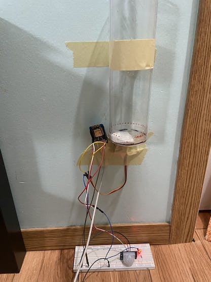
There are many ways to build the food container. One of the simplest ways is by using a plastic container and cardboard. This tutorial uses a plastic tube as the food container since we wanted to focus on the electronics part of the project but you can find a tutorial on how to make a pretty fancy container here.
First cut a small hole on the bottom of the plastic food container and use a small piece of cardboard as the lid to cover the hole on the plastic food container. Then, glue the cardboard lid to the shaft of the servo motor. Both the servo motor and the plastic food container should be taped to the wall to keep them fixed.
Now that we have finished building the container, we need to make sure the servo motor can rotate the lid to dispense food.
In your firmware, change the initial position of the servo motor and the angle that you want the motor to rotate. The servo motor should return to the initial position after food is dispensed.
The variable ServoInitialPosition stores the initial position of the servo motor. When the servo motor is at this position, the lid should cover the hole of the cardboard box to prevent food from leaking out of the container. The other variable ServoFinalPosition stores the angle that you want the motor to rotate to dispense food.
const int ServoInitialPosition = 0; //starting position
const int ServoFinalPosition = 135; //final position
5. Final Testing
Now our homemade IoT pet feeder is ready for testing. Power up the pet feeder by connecting the micro-USB port of the WeMos D1 Mini board through a USB cable. Depending on the design of your pet feeder and the components you used to build the pet feeder, you may need to make small modifications in the code.
Conclusion
Overall, we have gained familiarity with the WeMos D1 Mini and Blynk IoT platform using the Arduino IDE, and ended up with an awesome IoT Dog Feeder to show for it!
If you liked this project please share it with others so we can keep on making these types of projects! If you're interested in more content from us you can visit our Learning Hubfor more great and accessible electronics education.
Schematics
Final Circuit Diagram
Code
FInal Project Code
Arduino
/*************************************************************************************
    FILENAME: automatic_dog_feeder.ino

    DESCRIPTION:
    This is a script for a automatic dog feeder project using a WeMos D1 Mini, PIR
    sensor, servo motor, and the Blynk IoT Platform. You can find the full
    instructions to this project here:

    DATE: May 5, 2022

    LEARNING HUB:
    For more accessible education materials, please check out the Gentiam Electronics
    Learning Hub at:
    https://www.gentiam.com/learning-hub/

    DISCLAIMERS:
    YOU AGREE TO USE THIS CODE, OR ANY OTHER OBTAINED FROM ANY GENTIAM ELECTRONICS
    SITE OR SOCIAL MEDIA LOCATION, AT YOUR OWN DISCRETION AND RISK. YOU WILL BE
    SOLELY RESPONSIBLE FOR ANY DAMAGE TO YOUR COMPUTER SYSTEM OR LOSS OF DATA THAT
    RESULTS FROM THE DOWNLOAD OF ANY SUCH MATERIALS.

    THE COMPLETE TERMS OF USE FOR ANY MATERIALS OBTAINED FROM ANY GENTIAM ELECTRONICS
    SITE, INCLUDING THIS CODE, CAN BE FOUND AT
    https://www.gentiam.com/legal/

**************************************************************************************/

#define BLYNK_TEMPLATE_ID "Replace with your template ID"
#define BLYNK_DEVICE_NAME "Quickstart Template"

#include <BlynkSimpleEsp8266.h>
#include <Servo.h>
#include <SimpleTimer.h>

// Define pins for the PIR Motion Sensor
int PIR_pin = D7;
int PIR_status = 0;

// Servo Motor
Servo ServoMotor;
int ServoPin = D4;

const int ServoInitialPosition = 0; // Starting position of servo motor
const int ServoFinalPosition = 135; // Final position of servo motor

// LED for PIR motion sensor
int ledPin = D2;

SimpleTimer timer;
int counter = 0;
int flag = 1; // Set a flag to make sure the program only sends one notification if motion is detected continuously

// ESP8266
char auth[] = "Your Blynk Auth Token"; //Blynk token
char ssid[] = "Replace with your WiFi SSID"; //Your WiFI SSID
char pass[] = "Replace with your WiFi password"; //Your Wifi password

// Create a button to control the servo motor
// This is a standalone function and can't be used inside of any loop or function.
// Go to Blynk documentation for more details: https://docs.blynk.io/en/blynk.edgent-firmware-api/virtual-pins
BLYNK_WRITE(V1)
{
  int pinValue = param.asInt(); // Assign incoming value from pin V1 to the variable pinValue

  if (pinValue == 1)
  {
    ServoMotor.attach(ServoPin); // Enable control signal of the servo motor
    ServoMotor.write(ServoFinalPosition); // Rotate the shaft to the final position
    delay(1000);
    ServoMotor.write(ServoInitialPosition); // Rotate the shaft to the initial position
    delay(1000);
    ServoMotor.detach(); // Disable control signal
    Blynk.logEvent("food_dispensed", "Food Dispensed!"); // Send a notification to the user
  }
  //Serial.print("V1 button value is: ");
  //Serial.println(pinValue);
}

void PIR_sensor(){
  counter++;
  Serial.println(counter);

  // Turn off LED if no motion has been detected for 30 seconds
  if (counter == 10)
  {
    digitalWrite(ledPin, LOW);
    counter = 0;
    flag = 1;
  }

  PIR_status = digitalRead(PIR_pin);
  //Serial.println(PIR_status);

  if (PIR_status == HIGH)
  {
      if (flag == 1)
      {
        Serial.println("Motion Detected!");
        Blynk.logEvent("motion_detected", "Motion Detected!");
        // If motion is detected, turn on LED
        digitalWrite(ledPin, HIGH);
        counter = 0;
        flag = 0;
      }
  }
  else
  {
      Serial.println("Motion Stopped!");
  }
}

void setup() {
  Serial.begin(9600);
  Serial.println("Start!");

  Serial.print("Connecting...");

  Blynk.begin(auth, ssid, pass);

  pinMode(PIR_pin, INPUT_PULLUP);
  pinMode(ledPin, OUTPUT);

  timer.setInterval(3000L,PIR_sensor); // Detects motion every 3 seconds
}

void loop() {
  Blynk.run();
  timer.run();
}
///////////////////////////////////////////////////////////////////
//   Copyright 2022 Gentiam Electronics - All Rights Reserved   //
///////////////////////////////////////////////////////////////////
The article was first published in hackster, Jul 29, 2022
cr: https://www.hackster.io/gentiam-electronics/iot-automatic-dog-feeder-9150d7
author: Gentiam Electronics


