
Many fun environmental sensors need a hardware interrupt. With the MKR1000, you no longer need to choose! You get I2C, analog ins too!

Things used in this project
Hardware components
Story
I love watching the weather, and I wanted to try to capture and graph it. Home weather stations let me see the details for "now", and sometimes tallies for the past hour, or day. I wanted to do more, and use an Arduino for the job. Everyone starts with Temperature and Humidity, sometimes Barometric Pressure, but I wanted more! Wind speed and rain measurement each wanted hardware inputs. Once I'd mastered using i2c, I found things like the AS3935 Lightning Detector! And then the sadness set in... I didn't have enough hardware interrupts to do the job with your basic Arduino. Sparkfun even has a weather sensor board for the Photon, but it's still limited. I'd have to choose, and do without some of the sensors. :-(
Then I saw the MKR1000, and I spotted the BEST FEATURE, it has 8 hardware interrupts! Now I could have it all!
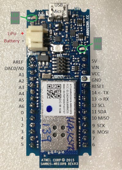
MKR1000 annotated pinouts, top view
Choosing your Sensors
Sensors come in three basic flavors;
Analog: light (including IR and UV), wind direction, gases, load cells... I2C: temp, humidity, baro pressure, accelerometer, gyro... Interrupts: rain tippers, wind speed, lightning, timers...(Features like serial, PWM, clocks, servos use timing interrupts)
The MKR1000 has plenty of I/O for all of these!
NOTE WHICH VOLTAGE YOU NEED FOR YOUR I/O on I2C and Interrupts! For example, the MKR1000, the Photon, and many flavors of Arduino use 3.3v I/O instead of 5v. If your CPU and the sensor(s) that you want use different voltages, you will also need to use level-shifters between those devices.
All of the sensors that I've been using are common enough, available from Adafruit, SparkFun, Element-14 and others, and usually cost between $5-10(US). Gas sensors usually cost $10-$20. For the lightning detector (AS3935 chip), I chose the Embedded Adventures MOD-1016, which is $26 (US) to get the antenna on the board as well. I also bought the Sparkfun Photon Weather Shield, since I have a Photon, and I'll probably buy their "weather meters" (wind speed and direction instruments). Maybe I'll add a Soil Moisture sensor, once I figure out where I'll be mounting the MKR1000. Some sensors do not like having long leads.
Assign your Sensors to Pins
Once you know which sensors you want, you'll know which type of inputs you will need, the next step is to decide which sensors will go on which pins. I start on paper, but I'll also add this list as a block comment in my code, as a reminder.
Here are the MKR1000 pin assignments that I've made for my sensor deck.
A0 (I'm saving A0 in case I need the DAC later...)A1 ML8511 UV sensorA2 visible light sensorA3 TMP36 local temp sensorA4 MQ-9 gas sensorA5 moisture sensorA6 wind speed sensor?0 (HW INT) pushbutton1 (HW INT) AS Lightning Detector2 (HW INT) wind speed anemometer (interrupt per rotation)3 (HW INT) Rain Tipper…456 (shared with on-board LED)7 NeoPixel output…
Getting Started...
For the beginners among you, I suggest starting with each sensor you are going to use, one at a time, and start by loading the example code, and installing the needed libraries. Remember to change the sensor pin, to match the pin assignment of your choice, and save a copy of the demo code in your project folder.
When you can run the test code, and read the results from the Serial Monitor, you are ready to try adding another. And when you are done testing each sensor, they are now all wired and ready to start building your larger sketch!
My original tinkering with the sensors included using an i2c-based Reat-Time Clock (RTC), so I could log to an SD memory card. Although the MKR1000 has it's own RTC, and a battery, I haven't been able to get the clock to keep time with only the battery, so I'll be keeping the ChronoDot v2.1 i2c RTC as well.
Looking at the breadboard in my image below, you can see the various jumpers in use. The orange are for the 3.3v power to each sensor, so I can only plug them in when I'm ready to work with them. (It's easy to disable a sensor by unplugging the orange jumper.)
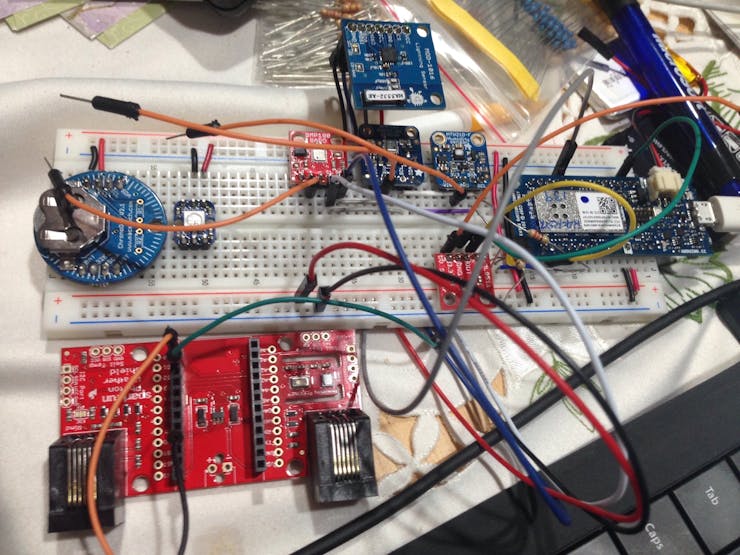
My sensor deck, on a breadboard, with the Photon Weather Shield and assorted sensors.
A Note about Libraries
I've found that some of the libraries that you can install, do NOT work perfectly with the MKR1000, and/or with Arduino.cc IDE version 1.6.7, and you may need to do some tuning, depending on how old your sensor is. One example of this is the older ATOMIC_* macros in the older AVR libc library (they were dropped in Arduino IDE 1.6.5), and there is a great thread about problems and suggested solutions in a forum thread on Arduino.cc. Making some of the suggested changes are something for an intermediate Arduino hacker, but will probably be intimidating for newer hackers. And, for slightly older libraries, the original author may not be around to update the library and eliminate the dependency.
Unfortunately, you usually won't be able to know which libraries need to be tuned before you buy your sensors and test them. At that point, I recommend that you look at the error messages that appear in orange when you try to upload your sketch carefully, to see if the problem is in your code, or in a library, before you start changing your code. If it's in the library, do a web search for "arduino" and the error message. If you can't find a solution, try to email the author, and let them know about the error, and maybe they will update the library.
I've bought individual chips, trying to save money. I've decided that, until I'm ready and able to make my own circuit boards (probably using EagleCAD and OSHPark), it's easier to buy sensor modules from Adafruit and SparkFun, since they are great about keeping their libraries patched.
A Bit about WiFi and Encryption
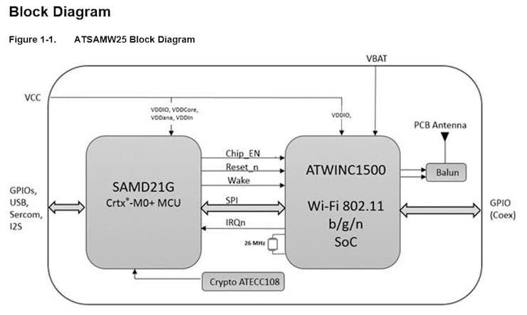
I also thought about the wifi for making my weather sensors report in to a website. We even have an encryption engine on the MKR1000, to help keep our data safe in transit over the Internet! But, that's more than I will be able to do in this first project. It's on my list to do, because making data security part of your design is important for the Internet of Things, but I am running out of time for adding my entry for the MKR1000 contest. Watch for my "version 2" of this project. Here is a block diagram of the SAMD module that is the heart of your board.
I can offer you one tip to get started with the on-board WiFi: Make sure that you are using the most current version of the WiFi101 library! If you do not, your sketch won't recognize the wifi module, and your wifi sketches will only report that if there is error checking on the calls to the wifi module.) I need to thank Charif Mahmoudi for pointing that out in his great "Getting Started with MKR1000" tutorial here on Hackster! At the time of my hacking, you could find the WiFi101 Githuib here.
Tips for Analog Sensors
Most "analog output" sensor modules will produce a simple analog voltage output, and this is easily read using the analogRead of the sensor pin. But, then you need to know what that means. Normally, you will need to use the map command, or you may need to perform a bit of math. Resistive elements will usually need some extra circuitry. You may want to add a potentiometer to "fine-tune" the voltage.
In other cases, you'll need equations to turn the output voltage into something that humans will understand. The TMP36 temperature sensor is one well-documented example of this. This part was designed to read out in degrees Celsius, so you need to measure the voltage, and do some math to get C, and if you want Fahrenheit, you'll need to convert C to F. Reading the data sheets of components will explain how the part works, but you will find it easier to follow in someone else's footsteps as you build up your experience.
Yet other sensors need an amplifier, in order to make the tiny voltage swings large enough for your ADC to get a good range from high to low. These types of sensors (load cells, moisture, accelerometer) are where I find it best to spend some money, and buy a module that already has an amp, and a library to help understand the range of the output.
Tips for Using I2C Devices
I2C is sometimes called a "two-wire interface", because you need a clock signal, as well as a data signal. (You only need one data wire, because the "master" and the "slave(s)" will take turns sending data on it.) Of course, your I2C sensors will also need a ground and a power lead as well, and that ground lead needs to be tied back to your CPU.
Every I2C device will have a hexidecimal address on the bus. It's best to avoid using multiple devices with the same address. (If you want to have multiples, you need to manage them with extra circuitry, in order to "enable" the one you want to communicate with, and then disable it when you are done, before you enable another for communication.) The documentation should tell you which address(es) a device can be. (NOTE: If you have two devices on the I2C bus with the same address, and both have an "Enable" or "Shutdown" pin, you will be able to disable one while the other is awake. However, you cannot just turn off power to the vdd pin, since the sensors can pick up some power from the SDA and SCL pins, and will result in bad readings for that address. The error-checking for I2C is not good enough to detect/correct for this case.)
The I2C specifications tell us that we should have a "strong" pull-up resistor on both the clock and the data leads, on the sensor that is farthest on the wire. Because of this, some sensor modules already have resistors on-board, and you may just need to add a couple jumpers, so be sure to read the documentation for the module(s).
In addition to the "bus terminating resistors", I have also found a hint from one hacker long ago, to add a resistor in-line both the data (SDA) and clock (SCL) leads. This greatly improved the reliability of data readings from a couple of sensors. With the MKR1000, using 3.3v signaling, I'm using 220 ohm resistors. On a 5-v CPU, you may want to try 330 ohm. See the schematic below to see the difference in the placements.
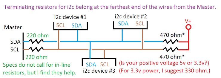
Suggested resistor placement on an I2C bus.
What will you do with the data?
Right now, I'm just sending it to the Serial Monitor. You could add an LCD. I was going to add an SD card, but now that I have wifi built-in, I want to upload the data to a cloud... imagine having a few of these sensor decks around, knowing their latitude and longitude, and being able to triangulate a lightning strike by comparing the power readings from each station for a given lightning strike!
ASIDE: 2017-11-29; I haven't been able to get the hardware interrupts working on the MKR1000. I'm making notes and sensor experiments for a Grade 9 class (age 13-14), and maybe you will find the sketches interesting. The class is built around the Adalogger M0 board, and saves the data to an SD card, and there are still plenty of pins for a WiFi module. http://arduinoclass.pbworks.com
While I've been working on the sensors, I also spotted the SODERSVIK lamp fixture at IKEA (See the image below.). Imagine replacing the white LEDs inside this lamp with 20 Neopixels, and adding an IR remote receiver. Blowing wind could look like clouds rolling by, and the color could indicate the temperature. The remote could also chose to momentarily show some other information, like the temperature change during the past 12 hours.
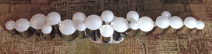
IKEA Sodesvik lamp (imagine it with 20 neopixel LEDs!)
What do you want to monitor and display?
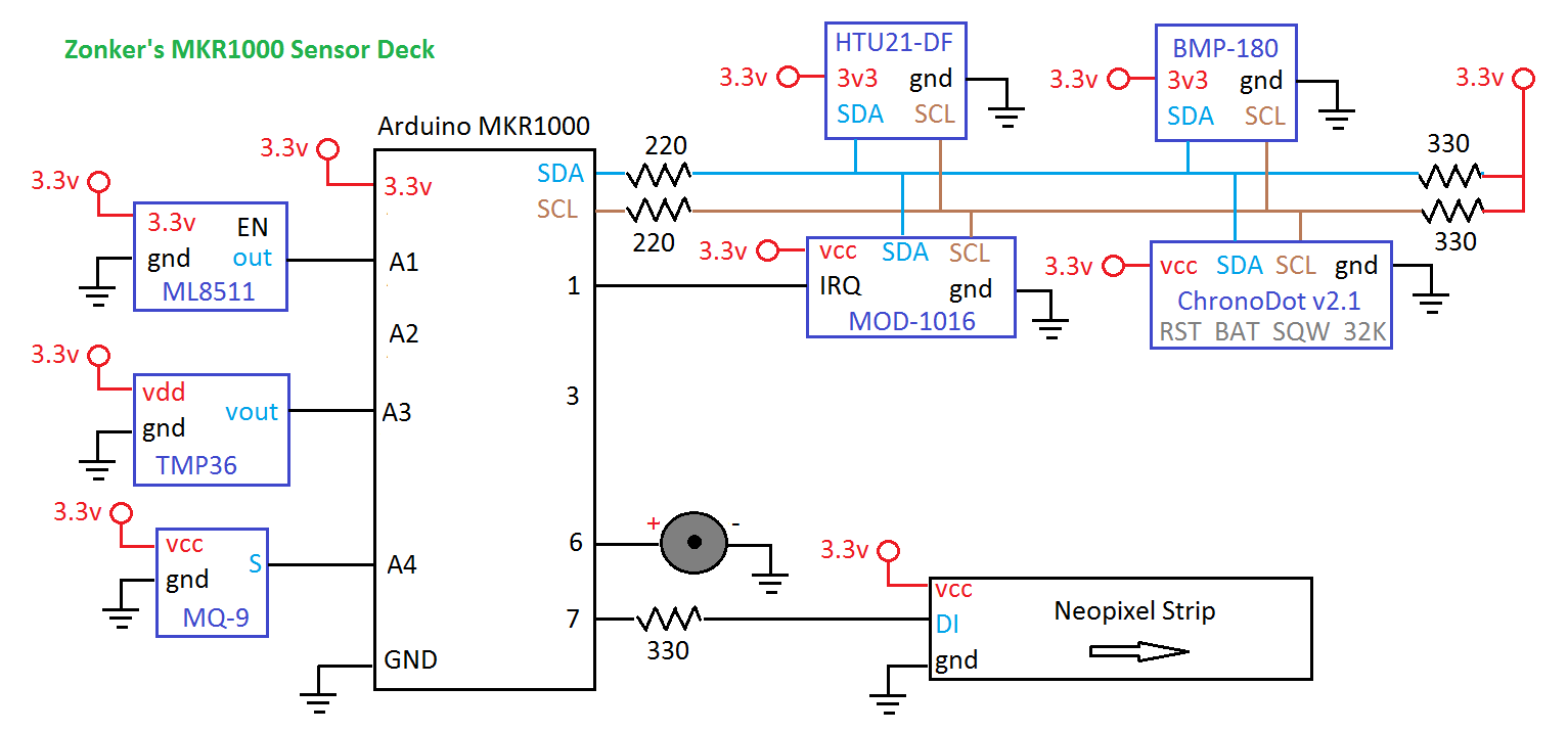
Schematics
Sensor Deck schematic
I'm too new to Fritzing, and couldn't find many parts in the library, so I made this mock-up instead.
Code
The entire monitoring sketch
Arduino
There are many sensors reporting in this sketch, and the libraries are working well together. However, the classic interrupt-locking methods in AVR-libc have been removed in the recent versions of the Arduino IDE, which has disabled the libraries for NeoPixel and for the Lightning sensor. I expect that this will be resolved this year sometime, but it means that I've left them out of the final sketch.
/* RTC-Weather-Sensors_v6_MKR1000   by Zonker Harris   Spring 2016
 *  Hooray! A small board, with more than 2 hardware interrupts!
 *  Plus WiFi, *and* crypto (VERY necessary for IoT applications!)
 *
 * Note to newer hackers:  I put MANY comments in my code, as you see.
 *  When you click upload, *comments are IGNORED*, and do not eat memory!
 *  I recommend that you also add plenty of comments when you make changes
 *  and additions, to help you remember WHY you did what you did months ago.
 *  They will also help those who come after you, to learn a thing or two.
 *
 * Now, libraries *DO* count against your program memory...
 */

#include <Wire.h>
#include <Adafruit_Sensor.h>
#include <Adafruit_BMP085_U.h>
#include <Adafruit_HTU21DF.h>

// Including neopixels as a placeholder, but the library interrupt vector needs updating.
// Include the Adafruit_NeoPixel library  https://github.com/adafruit/Adafruit_NeoPixel
//#include <Adafruit_NeoPixel.h>
//const int numLeds = 1;  // How many neopixels in the string? used to set the NeoPixel library
  // Parameter 1 = number of pixels in strip
  // Parameter 2 = pin number (most are valid)
  // Parameter 3 = pixel type flags, add together as needed:
  // NEO_RGB Pixels are wired for RGB bitstream
  // NEO_GRB Pixels are wired for GRB bitstream
  // NEO_KHZ400 400 KHz bitstream (e.g. FLORA pixels)
  // NEO_KHZ800 800 KHz bitstream (e.g. High Density LED strip)
//Adafruit_NeoPixel strip = Adafruit_NeoPixel(numLeds, 6, NEO_GRB + NEO_KHZ800);

/* The BMP085_U driver uses the Adafruit unified sensor library (Adafruit_Sensor),
   which provides a common 'type' for sensor data and some helper functions.
   (The BMP180 is comptible with this library, and gives the same output, but
    the library will identify the BMP180 as a BMP085.)

   To use this driver you will also need to download the Adafruit_Sensor
   library and include it in your libraries folder.

   You should also assign a unique ID to this sensor for use with
   the Adafruit Sensor API so that you can identify this particular
   sensor in any data logs, etc.  To assign a unique ID, simply
   provide an appropriate value in the constructor below (12345
   is used by default in this example).  */

Adafruit_BMP085_Unified bmp = Adafruit_BMP085_Unified(10180);

/*  This sketch also designed to work with the HTU21D-F sensor from Adafruit
      ----> https://www.adafruit.com/products/1899  */

Adafruit_HTU21DF htu = Adafruit_HTU21DF();

/*   Macetech Chronodot v2.1 Battery-backed Real-Time Clock (RTC)...
     http://docs.macetech.com/doku.php/chronodot
     (because the battery on my MKR1000 doesn't seem to keep the on-board RTC alive)

   The Adafruit Real-Time Clock (RTC) Library info
     https://learn.adafruit.com/adafruit-data-logger-shield/using-the-real-time-clock

   Analog Devices TMP36 analog calibrated temperature sensor.
     This requires some math  https://learn.adafruit.com/tmp36-temperature-sensor
     http://www.analog.com/media/en/technical-documentation/data-sheets/TMP35_36_37.pdf

   ML8511 UV sensor... This sensor detects 280-390nm light most effectively.
     This is categorized as part of the UVB (burning rays) spectrum and most of
     the UVA (tanning rays) spectrum.

   MOD-1016 (AS3935 Lightning Sensor)  i2c address 0x03 - AS3935 Lightning Sensor

   Adafruit has an anemometer which provides a DC voltage out (0.4-2.0v)
     https://www.adafruit.com/products/1733
     http://www.instructables.com/id/Breezefinder-Citizen-Science-Windpower-Tool/step2/Build-the-housing/

   Soil Moisture Detector  (YL-69 sensor or similar) requires analog input...
     http://www.instructables.com/id/Arduino-LCD-Soil-Moisture-Sensor/step3/Connect-moisture-sensor/

   My MKR1000 Connections (All sensors must be 3.3v signalling!)
   ===========  */
int UVOUT = A1; //  Output from the MV8511 UV sensor
int lightOut = A2; //  Output from the TEMT6000 visible light sensor
int tmp36out = A3; //  Output from the TMP36 local temperature sensor
int mq9out = A4; //  Output from DFrobot MQ-9 CO/Combustable Gs sensor
/* A5  Moisture Sensor
   A6  Wind speed sensor?
   0  (HW INT)  pushbutton
   1  (HW INT)  AS  Lightning Detector
   2  (HW INT)  wind speed anemometer? (interrupt per rotation)
   3  (HW INT)  Rain Tipper…
   4
   5   */
int sounderPin = 6; // Piezo Sounder output (shared with on-board LED)
//   (You can use a jumper to disable the sounder, but the on-board LED will blink)
int neopixelPin = 7; //  NeoPixel output, for visualization using shift-register-based LEDs
/*11  i2c SDA
  12  i2c SCL    */

// Decalring variables for the Chronodot i2c RTC...
int addrRTC = (0x68);  // RTC i2c address
int seconds;   //combined BCD from the RTC (00h)
int seconds1;  //0-9
int seconds10; //0-5
int minutes;   //combined BCD from the RTC (01h)
int minutes1;  //0-9
int minutes10; //0-6
int hours;     //combined BCD from the RTC (02h)
int hours1;    //0-9
int hours10;   //0-2
int day;       //1-7   (03h)
int date;      //01-31 (04h)
int month;     //01-12 (05h)
int years;     //0-99; (06h)
int a1secs;    // (07h) get Alarm 1 seconds
int a1mins;    // (08h) get Alarm 1 minutes
int a1hrs;     // (09h) get Alarm 1 hours
int a1daydate; // (0Ah) get Alarm 1 day and date bits
int a2mins;    // (0Bh) get Alarm 2 minutes
int a2hrs;     // (0Ch) get Alarm 2 hours
int a2daydate; // (0Dh) get Alarm 2 day and date bits
int rtcstatus; // (0Eh) get RTC status bits
int aginginfo; // (0Fh) get aging offset info
// what is 10h?
int temprtc;   //combined BCD from the RTC  (11h)
int tempfrtc;  //combined BCD from the RTC  (12h)


/**************************************************************************/
//  Arduino setup function (automatically called at startup)
/**************************************************************************/
void setup(void)
{
  Serial.begin(9600);
  delay(1000);
  Serial.println("i2c Sensor Deck");

// Remember to set up your inputs and output pins!
  pinMode(UVOUT, INPUT);  // the ML8511 UV sensor
  pinMode(lightOut, INPUT);  // the TEMT6000 visible light sensor
  pinMode(tmp36out, INPUT);  // the Analog Devices TMP36 temperature sensor
  pinMode(sounderPin, OUTPUT);  // HIGH will cause the sounder to emit noise
  pinMode(neopixelPin, OUTPUT);  // Use a 220-ohm resistor in-line to the strip

/* Initialize the BMP085/BMP180 sensor   */
  if(!bmp.begin())
  {
    /* There was a problem detecting the BMP085/180 ... check your connections */
    Serial.print("Ooops, no BMP085/180 detected ... Check your wiring or I2C ADDR!");
    while(1);
  }

  /* Display some basic information on this sensor, BMP180 reports as BMP085 */
  displaySensorDetails();

/* Initialise the HTU21D sensor */
  if (!htu.begin()) {
    Serial.println("Couldn't find the HTU21-DF sensor!");
    while (1);
  }

// Initialize the Chronodot RTC clock
//(change the values, uncomment, then upload to set the time, then comment it out again)
 /*
  seconds = 0;
  minutes = 41;
  hours = 20;
  day = 7;
  date = 3;
  month = 1;
  years = 16;
  initChrono();
*/
}

void loop(void)
{
  beep(50, 2); // announce the start of the loop on the sounder

  // Set the neopixel to Teal...
  //int red = 0;  int green = 45;  int blue = 30;
  //strip.setPixelColor(0, (red, green, blue));
  //strip.show();

/**********************************************************************/
/*  Pull the Chronot info   i2c address 0x68 - DS1307 RTC             */
/*  Board info: http://docs.macetech.com/doku.php/chronodot           */
/*  DS3231 datasheet: http://datasheets.maxim-ic.com/en/ds/DS3231.pdf */
/**********************************************************************/
  int temprtc;
  /* Get a new timestamp */
  Wire.beginTransmission(0x68); // 0x68 is DS3231 device address
  Wire.write((byte)0); // start at register 0
  Wire.endTransmission();
  Wire.requestFrom(0x68, 13); // request 19 bytes (is the # of bytes DEC or HEX?)
  // (seconds, minutes, hours, day, date, month, hrs,
  //  a1secs, a1mins, a1hrs
  //  a1secs, a1mins, a1hrs
  //  Aging offset, Temp integer, temp fraction)

  while(Wire.available())
  {
    seconds = Wire.read();       // (00h) get seconds
    minutes = Wire.read();       // (01h) get minutes
    hours = Wire.read();         // (02h) get hours
    day = Wire.read();           // (03h) get day of the week
    date = Wire.read();          // (04h) get date of the month
    month = Wire.read();         // (05h) get the month, and century bit
    years = Wire.read();          // (06h) get the year
    int a1secs = Wire.read();    // (07h) get Alarm 1 seconds
    int a1mins = Wire.read();    // (08h) get Alarm 1 minutes
    int a1hrs = Wire.read();     // (09h) get Alarm 1 hours
    int a1daydate = Wire.read(); // (0Ah) get Alarm 1 day and date bits
    int a2mins = Wire.read();    // (0Bh) get Alarm 2 minutes
    int a2hrs = Wire.read();     // (0Ch) get Alarm 2 hours
    int a2daydate = Wire.read(); // (0Dh) get Alarm 2 day and date bits
    int rtcstatus = Wire.read(); // (0Eh) get RTC status bits
    int aginginfo = Wire.read(); // (0Fh) get aging offset info
    temprtc = Wire.read();   // (11h) get integer portion of the temp, and sign
    tempfrtc = Wire.read();  // (12h) get the fractional portion of the temp

    //  Read our bits, and normalize the data with leading-zero padding
    // NOTE: The Chronodot doesn't know about Daylight Savings, shoulod your code?
    seconds10 = ((seconds & 0b11110000)>>4);
    seconds1 = ((seconds & 0b00001111));
    // convert BCD to decimal
    minutes10 = ((minutes & 0b11110000)>>4);
    minutes1 = (minutes & 0b00001111);
    // convert BCD to decimal
    hours10 = (((hours & 0b00100000)>>5)*2 + ((hours & 0b00010000)>>4)*1);
    hours1 = (hours & 0b00001111);
    // convert BCD to decimal (assume 24 hour mode)
    years = (years + 2000);
    temprtc = ((temprtc & 0b01111111) + (((tempfrtc & 0b11000000)>>6)*0.25));
    }

  get_date();
  // This is one place you could add Dayligh Savings Time decisions to alter hours...
  Serial.print("ChronoDot - ");
  Serial.print(hours10); Serial.print(hours1); Serial.print(":");
  Serial.print(minutes10); Serial.print(minutes1); Serial.print(":");
  Serial.print(seconds10); Serial.print(seconds1); Serial.print("  20");
  Serial.print(years); Serial.print(" ");
  Serial.print(month); Serial.print(" ");
  Serial.print(date); Serial.print(" \t");
  Serial.print(temprtc); Serial.println(" C");
  delay(100);  // so this will finish printing, in case the next sensor is stalled


/**********************************************************************/
/*  Get BMP180 data    i2c address 0x77 - BMP180 Baro Pres and Temp   */
/*  data: http://www.adafruit.com/datasheets/BST-BMP180-DS000-09.pdf  */
/**********************************************************************/
  sensors_event_t event;
  bmp.getEvent(&event);

    /* First we get the current temperature from the BMP085/BMP180       */
    float BMPtemperature;
    bmp.getTemperature(&BMPtemperature);
    float BMPtempF = (BMPtemperature * 1.8 + 32);
    Serial.print("Temp: ");
    Serial.print(BMPtemperature);
    Serial.print(" C (");
    Serial.print(BMPtempF);
    Serial.print(" F) \t");

  /* Display the results (barometric pressure is measure in hPa) */
  if (event.pressure)
  {
    /* Display atmospheric pressue in hPa */
    Serial.print("BMP180 - Pres: ");
    Serial.print(event.pressure);
    Serial.print(" hPa\t");

    /* Calculating altitude with reasonable accuracy requires pressure    *
     * sea level pressure for your position at the moment the data is     *
     * converted, as well as the ambient temperature in degress           *
     * celcius.  If you don't have these values, a 'generic' value of     *
     * 1013.25 hPa can be used (defined as SENSORS_PRESSURE_SEALEVELHPA   *
     * in sensors.h), but this isn't ideal and will give variable         *
     * results from one day to the next.                                  *
     *                                                                    *
     * You can usually find the current SLP value by looking at weather   *
     * websites or from environmental information centers near any major  *
     * airport.                                                           *
     *                                                                    *
     * convert inches-mercury http://www.csgnetwork.com/pressinmbcvt.html *
     *
     * For example, for Paris, France you can check the current mean      *
     * pressure and sea level at: http://bit.ly/16Au8ol                   */

    /* Then convert the atmospheric pressure, and SLP to altitude         */
    /* Update this next line with the current SLP for better results      */
    float seaLevelPressure = SENSORS_PRESSURE_SEALEVELHPA;
    Serial.print("Alt: ");
    Serial.print(bmp.pressureToAltitude(seaLevelPressure,
                                        event.pressure));
    Serial.println(" m");
    delay(100);  // so this will finish printing, in case the next sensor is stalled
  }
  else
  {
    Serial.println("Sensor error");
  }


/**********************************************************************
/* Get HTU21-DF data    i2c address 0x40 -  Humidity and Temp Sensor  *
/*   Then convert the atmospheric pressure, and SLP to altitude       *
/*   Update this next line with the current SLP for better results    *
/*   https://learn.adafruit.com/adafruit-htu21d-f-temperature-humidity-sensor/overview
/**********************************************************************/
    float HTUtemperature = htu.readTemperature();
    float HTUtempF = (HTUtemperature * 1.8 + 32);
  Serial.print("HTU21-DF - Temp: "); Serial.print(HTUtemperature);
  Serial.print(" C ("); Serial.print(HTUtempF);
  Serial.print(" F)\tHum: "); Serial.print(htu.readHumidity());
  Serial.println("%");
  delay(100);  // so this will finish printing, in case the next sensor is stalled


/**********************************************************************
/* Analog Devices venerable TMP36 precision temperature sensor
/*  this requires a bit of math after reading the output...
/*  https://learn.adafruit.com/tmp36-temperature-sensor/using-a-temp-sensor
/**********************************************************************/
 //getting the voltage reading from the temperature sensor
 int reading = averageAnalogRead(tmp36out);

 // 0.0032258064516129 are the DAC unit for 3.3v
 float tmp36voltage = 0.0032258064516129 * reading;

 // print out the voltage
 Serial.print("TMP36 - temp: ");
 float tmp36temperatureC = (tmp36voltage - 0.5) * 100 ;
 //converting from 10 mv per degree with 500 mV offset to degrees ((voltage - 500mV) times 100)
 Serial.print(tmp36temperatureC); Serial.print(" C \t");

 // now convert to Fahrenheit
 float tmp36temperatureF = (tmp36temperatureC * 9.0 / 5.0) + 32.0;
 Serial.print(tmp36temperatureF); Serial.print(" F, out: ");

 Serial.print(tmp36voltage); Serial.println("v");
  delay(100);  // so this will finish printing, in case the next sensor is stalled


/**********************************************************************
 * Vishay TEMT6000 Visible Light sensor - analog reading
 * https://www.sparkfun.com/products/8688
/**********************************************************************/
  int vLevel = averageAnalogRead(lightOut);
  // 0.0032258064516129 is (3.3v (the DAC ref voltage) \ 1023 * uvLevel)
  float newVOutVolts = 0.0032258064516129 * vLevel;

  Serial.print("TEMT6000 out: ");
  Serial.println(vLevel);
  delay(100);  // so this will finish printing, in case the next sensor is stalled


/**********************************************************************
 * ML8511 UV Sensor  - analog reading
 * https://learn.sparkfun.com/tutorials/ml8511-uv-sensor-hookup-guide *
/**********************************************************************/
  int uvLevel = averageAnalogRead(UVOUT);
  // 0.0032258064516129 is (3.3v (the DAC ref voltage) \ 1023 * uvLevel)
  float newOutVolts = 0.0032258064516129 * uvLevel;

  //Convert the voltage to a UV intensity level
  float uvIntensity = mapfloat(newOutVolts, 0.99, 2.8, 0.0, 15.0);

  Serial.print("ML8511 UV out: ");
  Serial.print(uvLevel);

  Serial.print(" / UV Intensity (mW/cm^2): ");
  Serial.println(uvIntensity);
  delay(100);  // so this will finish printing, in case the next sensor is stalled


/**********************************************************************
 * DFrobot MQ-9 CO/Combustable Gas sensor - analog reading
 * http://www.dfrobot.com/wiki/index.php/Analog_Gas_Sensor(MQ9)_(SKU:SEN0134)
 * https://www.pololu.com/category/83/gas-sensors  There are many available
 * But, deciphering what the output levels mean is an exercise for the buyer. :-(
/**********************************************************************/
  int MQ9volts = analogRead(mq9out);  // Read Gas value from the MQ-9 sensor
  Serial.print("MQ-9 Gas: "); Serial.println(MQ9volts,DEC);
  delay(100);  // so this will finish printing, in case the next sensor is stalled


  Serial.println("");
  delay(3500); // looking to time the loop at about 5 seconds...
  // End of the main loop...
}

/**************************************************************************/
/*  The code below are supporting subroutines                             *
/**************************************************************************/
/* Chronodot-related subroutines                                          *
 *   initChrono, set_date, get_date, set_time, get_time, get_temp,        *
 *   setHour, SetMinutes, decToBcd, bcdToDec                              */
/**************************************************************************/
void initChrono()
{
  set_time();
  set_date();
}

void set_date()
{
  Wire.beginTransmission(104);
  Wire.write(4);
  Wire.write(decToBcd(day));
  Wire.write(decToBcd(date));
  Wire.write(decToBcd(month));
  Wire.write(decToBcd(years));
  Wire.endTransmission();
}

void get_date()
{
  Wire.beginTransmission(104);
  Wire.write(3);//set register to 3 (day)
  Wire.endTransmission();
  Wire.requestFrom(104, 4); //get 4 bytes(day,date,month,year);
  day   = bcdToDec(Wire.read());
  date  = bcdToDec(Wire.read());
  month = bcdToDec(Wire.read());
  years  = bcdToDec(Wire.read());
}

void set_time()
{
  Wire.beginTransmission(104);
  Wire.write((byte)0);
  Wire.write(decToBcd(seconds));
  Wire.write(decToBcd(minutes));
  Wire.write(decToBcd(hours));
  Wire.endTransmission();
}

void get_time()
{
  Wire.beginTransmission(104);
  Wire.write((byte)0);//set register to 0
  Wire.endTransmission();
  Wire.requestFrom(104, 3);//get 3 bytes (seconds,minutes,hours);
  seconds = bcdToDec(Wire.read() & 0x7f);
  minutes = bcdToDec(Wire.read());
  hours = bcdToDec(Wire.read() & 0x3f);
}

void get_temp()
{
  Wire.beginTransmission(104);
  Wire.write((byte)0);  //set register to 0
  Wire.endTransmission();
  Wire.requestFrom(104, 3);//get 3 bytes (seconds,minutes,hours);
  seconds = bcdToDec(Wire.read() & 0x7f);
  minutes = bcdToDec(Wire.read());
  hours = bcdToDec(Wire.read() & 0x3f);
}

void setHour()
{
  hours++;
  if (hours > 23)
  {
    hours = 0;
    seconds = 0;
    minutes = 0;
  }
  set_time();

}
void setMinutes()
{
  minutes++;
  if (minutes > 59)
  {
    minutes = 0;

  }
  seconds = 0;

  set_time();
}

byte decToBcd(byte val)
{
  return ( (val / 10 * 16) + (val % 10) );
}

byte bcdToDec(byte val)
{
  return ( (val / 16 * 10) + (val % 16) );
}

/**************************************************************************/
/*   Displays some basic information on this sensor from the unified
    sensor API sensor_t type (see Adafruit_Sensor for more information)   */
/**************************************************************************/
void displaySensorDetails(void)
{
  sensor_t sensor;
//  bmp.getSensor(&sensor);
  Serial.println("------------------------------------");
  Serial.print  ("Sensor:       "); Serial.println(sensor.name);
  Serial.print  ("Driver Ver:   "); Serial.println(sensor.version);
  Serial.print  ("Unique ID:    "); Serial.println(sensor.sensor_id);
  Serial.print  ("Max Value:    "); Serial.print(sensor.max_value); Serial.println(" hPa");
  Serial.print  ("Min Value:    "); Serial.print(sensor.min_value); Serial.println(" hPa");
  Serial.print  ("Resolution:   "); Serial.print(sensor.resolution); Serial.println(" hPa");
  Serial.println("------------------------------------");
  Serial.println("");
  delay(500);
}

/**************************************************************************/
/* Takes an average of readings on a given pin, Returns the average       *
/*   used for the TMP36 and ML8511 UV Sensor readings.
/**************************************************************************/

int averageAnalogRead(int pinToRead)
{
  byte numberOfReadings = 8;
  unsigned int runningValue = 0;

  for(int x = 0 ; x < numberOfReadings ; x++)
    runningValue += analogRead(pinToRead);
    runningValue /= numberOfReadings;
    return(runningValue);
}

//The Arduino Map function but for floats
//From: http://forum.arduino.cc/index.php?topic=3922.0
float mapfloat(float x, float in_min, float in_max, float out_min, float out_max)
{
  return (x - in_min) * (out_max - out_min) / (in_max - in_min) + out_min;
}


void beep(int duration, int count)
{
  for(int loop = 0 ; loop < count ; loop++) {
    digitalWrite(sounderPin, HIGH);
    delay(duration);
    digitalWrite(sounderPin, LOW);
    delay(duration);
  }
}
Taking an Average Analog Reading
Arduino
This was a clever hack I found in the SparkFun library for the ML8511 UV Sensor, but I'm calling it out specifically, since you can use it for any analog read! If you ever meet Nathan Seidl, please buy him a beer (it's a Beerware license.)
//Takes an average of readings on a given pin
//Returns the average
int averageAnalogRead(int pinToRead)
{
  byte numberOfReadings = 8;
  unsigned int runningValue = 0;

  for(int x = 0 ; x < numberOfReadings ; x++)
    runningValue += analogRead(pinToRead);
  runningValue /= numberOfReadings;

  return(runningValue);
}
I2C bus scanner
Arduino
If you don't know the base address for your i2c devices, use this to scan the range of valid addresses. It knows about the sensors that I've been working with. You can add sections for your other sensors.
// --------------------------------------
// i2c_scanner
//
//   Found at http://playground.arduino.cc/Main/I2cScanner?action=sourceblock&num=1
//     26 OCT 2015
//
// Version 1
//    This program (or code that looks like it)
//    can be found in many places.
//    For example on the Arduino.cc forum.
//    The original author is not know.
// Version 2, Juni 2012, Using Arduino 1.0.1
//     Adapted to be as simple as possible by Arduino.cc user Krodal
// Version 3, Feb 26  2013
//    V3 by louarnold
// Version 4, March 3, 2013, Using Arduino 1.0.3
//    by Arduino.cc user Krodal.
//    Changes by louarnold removed.
//    Scanning addresses changed from 0...127 to 1...119,
//    according to the i2c scanner by Nick Gammon
//    http://www.gammon.com.au/forum/?id=10896
// Version 5, March 28, 2013
//    As version 4, but address scans now to 127.
//    A sensor seems to use address 120.
//
// This sketch tests the standard 7-bit addresses
// Devices with higher bit address might not be seen properly.
//
// Zonker Harris added device descriptions, comments.  OCT 10 2015
//

#include <Wire.h>

void setup()
{
  Wire.begin();

  Serial.begin(9600);
  Serial.println("\nI2C Scanner");
}

void loop()
{
  byte error, address;
  int nDevices;

  Serial.println("Scanning...");

  nDevices = 0;
  for(address = 1; address < 127; address++ )
  {
    // The i2c_scanner uses the return value of
    // the Write.endTransmisstion to see if
    // a device did acknowledge to the address.
    Wire.beginTransmission(address);
    error = Wire.endTransmission();

    if (error == 0)
    {
      Serial.print("I2C device found at address 0x");
      if (address<16)
        Serial.print("0");
      Serial.print(address,HEX);
      // Serial.print(address);  If needed, print the address in decimal
      //
      // Now, detail sensors that we know about or expect...
      if (address == 3)
      {
        // DEC 3 = 0x03 HEX = AS3935 Lightning Sensor
        Serial.print(" - AS3935 Lightning Sensor");
      }
      if (address == 64)
      {
        // DEC 64 = 0x40 HEX = HTU21D  Humidity and Temp Sensor
        Serial.print(" - HTU21D Humidity and Temp Sensor");
      }
      if (address == 104)
      {
        // DEC 104 = 0x68 HEX = DS1307 (Chrono-Dot?) RTC
        Serial.print(" - DS1307 RTC (Chrono-Dot?)");
      }
      if (address == 119)
      {
        // DEC 119 = 0x77 HEX = BMP180 Barometric Pressure and Tem Sensor
        Serial.print(" - BMP180 Barometric Pressure and Tem Sensor");
      }
      Serial.println(" ");

      nDevices++;
    }
    else if (error==4)
    {
      Serial.print("Unknow error at address 0x");
      if (address<16)
        Serial.print("0");
      Serial.println(address,HEX);
            if (address == 3)
      {
        // DEC 3 = 0x03 HEX = AS3935 Lightning Sensor
        Serial.print(" - AS3935 Lightning Sensor");
      }
      if (address == 64)
      {
        // DEC 64 = 0x40 HEX = HTU21D  Humidity and Temp Sensor
        Serial.print(" - HTU21D Humidity and Temp Sensor");
      }
      if (address == 104)
      {
        // DEC 104 = 0x68 HEX = DS1307 (Chrono-Dot?) RTC
        Serial.print(" - DS1307 RTC (Chrono-Dot?)");
      }
      if (address == 119)
      {
        // DEC 119 = 0x77 HEX = BMP180 Barometric Pressure and Tem Sensor
        Serial.print(" - BMP180 Barometric Pressure and Tem Sensor");
      }
    }
  }
  if (nDevices == 0)
    Serial.println("No I2C devices found\n");
  else
    Serial.println("done\n");

  delay(5000);           // wait 5 seconds for next scan
}

/*  The output looks like this...
 *
 * Scanning...
 * I2C device found at address 0x03 - AS3935 Lightning Sensor
 * I2C device found at address 0x40 - HTU21D Humidity and Temp Sensor
 * I2C device found at address 0x68 - DS1307 RTC (Chrono-Dot?)
 * I2C device found at address 0x77 - BMP180 Barometric Pressure and Tem Sensor
 * done
 *
 */
ML8511 Demo Code
Arduino
Modified for use with a 3.3v-native CPU (for DAC reference units).
/*
 *  From  https://learn.sparkfun.com/tutorials/ml8511-uv-sensor-hookup-guide 19 MAR 2016
 *    (Adapted for MKR1000 by Zonker Harris, MAR 2016)
 ML8511 UV Sensor Read Example
 By: Nathan Seidle
 SparkFun Electronics
 Date: January 15th, 2014
 License: This code is public domain but you buy me a beer if you use this and we meet someday (Beerware license).

 The ML8511 UV Sensor outputs an analog signal in relation to the amount of UV light it detects.

 Connect the following ML8511 breakout board to Arduino:
 3.3V = 3.3V
 OUT = A1
 GND = GND
 EN = 3.3V

 * The Sparkfun demo presumes 5v VCC, but the MKR1000 is 3.3v native.
 * Because of this, the second reference voltage value will always be "1023".
 * As a result of testing, I cut that part out...  -Z-

 Test your sensor by shining daylight or a UV LED: https://www.sparkfun.com/products/8662

 This sensor detects 280-390nm light most effectively. This is categorized as part of the
 UVB (burning rays) spectrum and most of the UVA (tanning rays) spectrum.

 There's lots of good UV radiation reading out there:
 http://www.ccohs.ca/oshanswers/phys_agents/ultravioletradiation.html
 https://www.iuva.org/uv-faqs

*/

//Hardware pin definitions
int UVOUT = A1; //Output from the sensor

void setup()
{
  Serial.begin(9600);
  pinMode(UVOUT, INPUT);
  Serial.println("ML8511 example");
}

void loop()
{
  int uvLevel = averageAnalogRead(UVOUT);
  float newOutVolts = 0.0032258064516129 * uvLevel;  // This is 3.3v \ 1023 * uvLevel

  float uvIntensity = mapfloat(newOutVolts, 0.99, 2.8, 0.0, 15.0);
    //Convert the voltage to a UV intensity level

  Serial.print("ML8511 out: ");
  Serial.print(uvLevel);

  Serial.print(" / UV Intensity (mW/cm^2): ");
  Serial.print(uvIntensity);

  Serial.println();

  delay(100);
}

//Takes an average of readings on a given pin
//Returns the average
int averageAnalogRead(int pinToRead)
{
  byte numberOfReadings = 8;
  unsigned int runningValue = 0;

  for(int x = 0 ; x < numberOfReadings ; x++)
    runningValue += analogRead(pinToRead);
    runningValue /= numberOfReadings;
    return(runningValue);
}

//The Arduino Map function but for floats
//From: http://forum.arduino.cc/index.php?topic=3922.0
float mapfloat(float x, float in_min, float in_max, float out_min, float out_max)
{
  return (x - in_min) * (out_max - out_min) / (in_max - in_min) + out_min;
}
The article was first published in hackster, March 21, 2016
cr: https://www.hackster.io/consoleteam/multiple-mode-environmental-sensor-deck-with-mkr1000-f184a6
author: ConsoleTeam: Zonker Harris, Dr. Charif Mahmoudi


