
Learn how to build a sensor that detects moisture levels in your plant and reports them via BLE to a mobile app – no programming required!

Things used in this project
Hardware components
Hand tools and fabrication machines
Breadboard, 170 Pin
Story
Full YouTube Tutorial
✅ Note: No Programming Is Required For This Project!
Introduction
Would you like to detect when your plant needs water?
Yes, you can simply follow general guidelines and water it at the specific recommended period. But every environment is different, and a plant will need more water than usual if there's excessive heat in the area.
A better and more accurate indicator would be to use what's called a soil moisture level sensor. These sensors output an analog signal based on the level of moisture detected in the medium it's placed in.
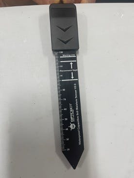
An example of such a sensor is the DFRobot Capacitive Soil Moisture Level Sensor:
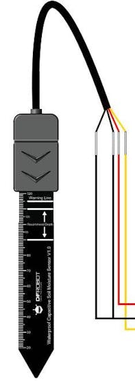
DFRobot Capacitive Corrosion Resistant Soil Mositure Level Sensor
The sensor will need to be connected to some type of chipset or platform through an Analog-to-Digital Converter (ADC), which will either display the levels on some kind of screen or send the data wirelessly to another device that can display the data. Learn more about Analog Digital Converters (ADC) here.
Being an IoT enthusiast myself, I prefer the wireless option. The most common wireless options are Bluetooth Low Energy (BLE) and Wi-Fi. Wi-Fi is more complex and requires connecting to a network of some sort. BLE, on the other hand, can operate peer-to-peer and send the data from a BLE-enabled chipset directly to your smartphone.
Normally, this would require you to write code and program the chipset connected to the sensor. But not with the InPlay NanoBeacon™ IN100.
The IN100 was built from the ground up to be Programming-Free! This means you don't need to write a single line of code or even know how to program.
The IN100 also features four ADC channels available on GPIO pins. For this project, we'll only need one to use one of these pins. Here's a table showing the assigned pin for each ADC channel:
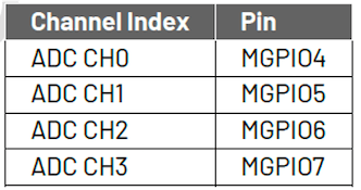
ADC Channels and their pin mappings on the IN100
Hardware Requirements
To get started, you'll need the following:
One InPlay NanoBeacon™ IN100 development board (included in the IN100 Evaluation Kit) One InPlay NanoBeacon™ IN100 programmer board (included in the IN100 Evaluation Kit) One DFRobot Analog Waterproof Capacitive Soil Moisture Sensor- Corrosion Resistant A PC running Windows, Linux, or macOS A breadboard Four female-to-male jumper wires Two 100 KΩ resistors A plant (or some other soil medium) Some water
Background Information
If you're unfamiliar with the InPlay IN100 chipset, I recommend you check out "Getting Started with the InPlay NanoBeacon™ IN100" (15 min) before moving on with this project.
The IN100's internal ADC has 11 bits referenced by an internal 0.8V bandgap reference. This means we have ADC values ranging from 0 to 2047, and the analog input signal range is from 0 to 2*RefVoltage (up to 1.6 volts).
Based on the documentation for the DFRobot soil moisture sensor, the output voltage ranges from 0 ~ 2.9 VDC. Since the maximum voltage (2.9 V) is higher than the supported voltage by the IN100's ADC (1.6 V), we'll need to utilize what's referred to as a voltage divider circuit.
Project Configuration Steps
Step #1: Build the circuit and connections
The first step is to build the circuit and make the necessary connections between the components.
For our project, we'll use two 100 KΩ resistors to divide the voltage in half (making the max output going into the ADC pin around 1.45 V, which is under the 1.6 V max input to the ADC).
Here's what the complete circuit looks like:
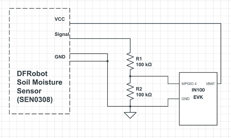
Project circuit
As you can see from the circuit, we'll be reading the voltage between the two equal resistors. This will ensure that the max voltage output is set to half of the max output voltage from the sensor.
The connections look like this:
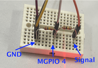
Voltage divider circuit
"GND" is connected to GND on both the IN100 development board and GND to the DFRobot sensor"MGPIO 4" is connected to MGPIO4 on the IN100 development board "Signal" is connected to the Signal line coming from the DFRobot sensor
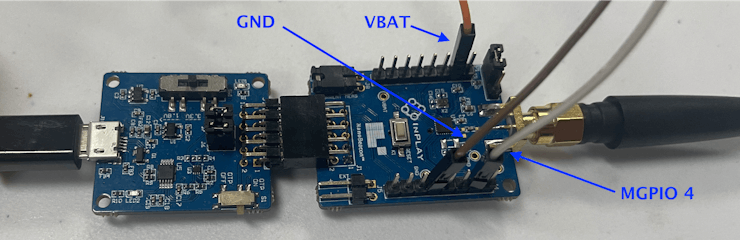
Connected pins on the IN100 development board (using ADC channel 0 – MGPIO4)
"GND" is connected to "GND" on the breadboard
"VBAT" is connected to the VCC line to the DFRobot sensor "MGPIO 4" is connected to "MGPIO 4" on the breadboard (junction connecting the two resistors)
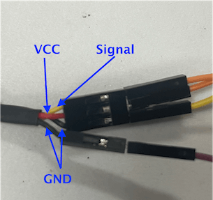
DFRobot soil moisture sensor wiring
"VCC" is connected to VBAT on the IN100 development board "Signal" is connected to the "Signal" label on the breadboard The two "GND" lines are both connected to the "GND" label on the breadboard
Step #2: Configure the IN100 Settings
Now, we're ready to configure the IN100 with the following:
ADC channel 0 is enabled and configured Advertising Set #1 is enabled and configured to include a device name (to make it easier to discover on the phone) and also include the readings from ADC channel 0
Let's go through each of these in detail.
Step #2A: Configure the ADC Settings
To configure the ADC settings for the IN100, we navigate to the "ADC" tab under "Application Settings" on the left-hand side.
Once in that tab, we need to enable ADC Channel 0:
Enabling ADC Channel 0
Once enabled, click on the Edit button.
In the ADC Configuration view, we see three sections:
Power Switch Select: this allows us to disable the power supply to the sensor during sleep cycles, which leads to lower power consumption and longer battery life.
We will leave this in the default setting: "None." Sampling Configuration: usually left in the default setting but can be modified to match any special application requirements.
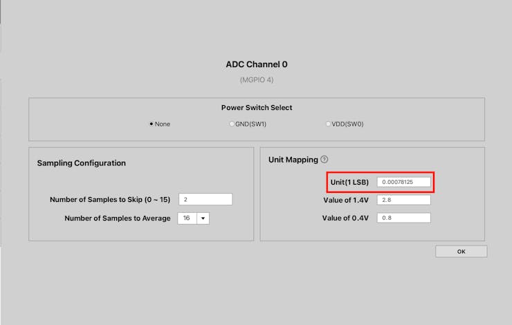
We will leave this in the default setting: Number of samples to skip = 2 and Number of samples to average = 16. Unit Mapping: for sensors with linear output voltage (such as in our case), we can modify the values to map the values that the IN100 reads to the original voltage output from the sensor.
- We will keep the "Unit" setting as is: 0.00078125.
- We will set the Value of 1.4 V = 2.8 V
- We will set the Value of 0.4 V = 0.8 V.
The reason behind these settings is that the original output voltage will be divided in half, so we need to map the values accordingly.
💡Tip: for non-linear sensors, please refer to the NanoBeacon™ Config Tool User Manual on converting the value. The User Manual can be downloaded from this web page.
Configuring ADC Channel 0
Once done with the configuration, hit OK. That's it in terms of ADC configuration.
Step #2B: Configure the Advertising Set
Next, we will configure Advertising Set #1 to include a device name ("IN100") and the ADC values. This will enable our device to broadcast data that can be discovered and read by a mobile phone (using a BLE Scanning app such as nRF Connect, Lightblue, or BLE Hero).
We will also set the Advertising Interval to 1,000 ms (1 second) to ensure that the values reflect more precise measurements during testing. Keep in mind this will affect the power consumption in the end product due to waking up the device and radio more often.
We will configure Advertising Set #1 with the following settings:
Choose Custom for the Advertising Data Format Inside Settings, enable Device Name and set it to IN100 (or feel free to choose any name you want) Enable Manufacturer Specific Data, then go into its Settings In the Dynamic Data settings, find and select ADC CH0 in the dropdown menu Enable the Big Endian setting (this will make interpreting the data easier) Click Append to Data Click OK Verify the broadcast data by viewing the Advertising Data
Configuring Advertising Data
To set the Advertising Interval, navigate to Advertising Parameters and set the Advertising Interval value to 1000 (ms).
That's it in terms of configuration; that was easy, right?
Step #3: Flash the configuration to the development board
Once you're done configuring your application, you can flash the IN100 with your new configuration. But first, make sure that the IN100 development board is connected to the programmer board and the computer.
Then, connect to the device via the UART menu:
Then flash the application to the development board by simply clicking the Run in RAM button:
Testing It Out
Finally, we're ready to test our application!
Let's recap all the steps we performed:
We connected all our components (sensor, resistors, IN100 development board) according to the design described at the beginning of the project. We connected the IN100 development board to the programmer board to the computer (via a USB cable). We configured the application via the NanoBeacon™ Config Tool. We connected to the development board via the UART options within the NanoBeacon™ Config Tool. Finally, we flashed the device with our configured application.
To test out our device and make sure it's working correctly, we will run three different tests:
1. Dry conditions – no water
2. Sensor fully immersed in water – at 100% level on the sensor scale
3. Sensor partially immersed in water – at 50% level on the sensor scale
To capture the data broadcast by the IN100 in the BLE advertising packets, we'll need to use a BLE scanner app.
There are many options available for both iOS and Android. I recommend one of the following apps: nRF Connect (iOS, Android), LightBlue (iOS), or BLE Hero (iOS).
For the tests performed here, I'll be using nRF Connect for Android.
Test #1: Dry condition
In dry conditions, we expect the sensor's output voltage to be at the max (≈ 2.9 V). This translates to an ADC reading ≈ 1.45 V (since it will be half the original voltage level).
For this test case, I simply made sure the sensor is dry:
When scanning in the mobile app, this is what I see:

Dry conditions ADC reading
Once we capture the ADC reading from the advertising packet, we need to convert it to decimal: 0xEE9 → 3817 decimal.
Finally, from the decimal value, we need to convert it to the corresponding voltage by multiplying the value with the Unit from the ADC Settings:
Unit for 1 LSB in ADC
So, the corresponding output voltage from the sensor for dry conditions (0 level on the sensor scale) = 3817 * 0.00078125 = 2.98 V.
Test #2: Fully immersed in water (100 on the sensor scale)
For this test case, I immersed the sensor up to the 100 level on the sensor scale:
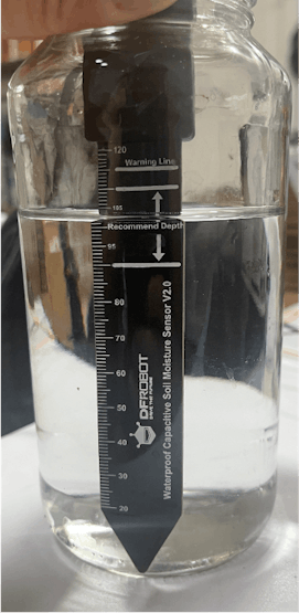
Fully immersed in water to the 100 level on the sensor scale
For 100%, when scanning in the mobile app, we see a value of 0x262:
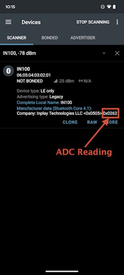
Level 100 advertising data ADC reading
We need to convert this value to decimal. 0x262 → 610 decimal.
Finally, from the decimal value, we need to convert it to the corresponding voltage by multiplying the value with the Measurement Unit from the ADC Settings (0.00078125).
So, the corresponding output voltage from the sensor for full immersion (100% moisture) = 610 * 0.00078125 = 0.48 V.
Test #3: Immersed in water up to level 50 on the sensor scale
For this test case, I immersed the sensor up to level 50 on the sensor scale:
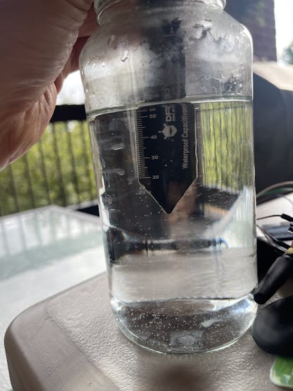
Sensor immersed to level 50 on the scale
For 50%, when scanning in the mobile app, we see a value of 0x903:

Level 50 advertising data ADC reading
We need to convert this value to decimal. 0x903 → 2307 decimal.
Finally, from the decimal value, we need to convert it to the corresponding voltage by multiplying the value with the Measurement Unit from the ADC Settings (0.00078125).
So, the corresponding output voltage from the sensor for full immersion (100% moisture) = 2307 * 0.00078125 = 1.80 V.
Since the sensor output is linear, if we wanted to predict the value of level 50 (based on levels 100 and 0), the value would be around:
Low voltage output + (max voltage output - low output voltage)/2
= 0.48 + (2.98-0.48)/2
= 0.48 + (2.5/2)
= 0.48 + 1.25
= 1.73 V, which is close to the reading we saw (1.8 V).
Summary and Conclusion
In the project, we saw how to connect an analog sensor to the IN100 and include the ADC readings in the broadcast data (advertising packets).
This is simply one example of an analog sensor that can be paired with the IN100 to create a broadcasting BLE device in a matter of minutes and without writing a single line of code!
There are many other sensors that you could use depending on your own custom application and use case.
Let me know in the comments below what type of sensor you would like to use with the IN100?
The article was first published in hackster, September 6, 2022
cr: https://www.hackster.io/mohammad-afaneh/wireless-soil-moisture-detector-using-the-inplay-in100-ca9fa8
author: Mohammad Afaneh


