Monitoring bee hive state with data retrieval on weight, temperature, humidity, luminosity and hive buzzing frequencies through sensors.
Things used in this project
Hardware components
Software apps and online services
beep monitor
The Things Network [https://www.hackster.io/the-things-network/products/the-things-network?ref=project-476c12]
diagrams
Hand tools and fabrication machines
PCB Holder, Soldering Iron
thermodynamic sheath
Soldering iron (generic)
multiple conductor cable
Story
In today's world, bee populations are in decline and the livelihood of beekeepers is at risk. To address this problem, our team at Polytech has developed an innovative solution to monitor the health and well-being of bee hives.
Here is a link to a small presentation video :
Presentation poster
-1_pgAzSNedik.jpg?auto=compress%2Cformat&w=740&h=555&fit=max)
Our system uses basic sensors and wireless technology to collect data on the weight, temperature, humidity, and buzzing frequencies of the hive, providing beekeepers with valuable insights into the hive's activity and overall health.
Our goal is to help protect bees and support the livelihoods of beekeepers by making it easier to manage and maintain healthy hives.
Report of the project progress:
Initially, we began by researching and selecting the appropriate sensors for data retrieval on the bee hive, including weight, temperature, luminosity, humidity, and hive buzzing frequencies, with the help of a microphone and an amplifier;
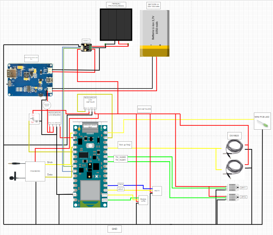
refer to the diagram given for the different connections and the pins that we used. It is coded and colored
Then we worked on The Thing Network to know how to connect the LoRa module with TTN and share this data to a website (ubidots, beep monitor)
You can follow this tutoriel that is well explained https://www.thethingsnetwork.org/docs/devices/uno/quick-start/
Then we moved on to designing and creating our PCB (printed circuit board) for housing these sensors and ensuring proper connections between them.
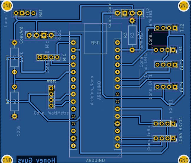
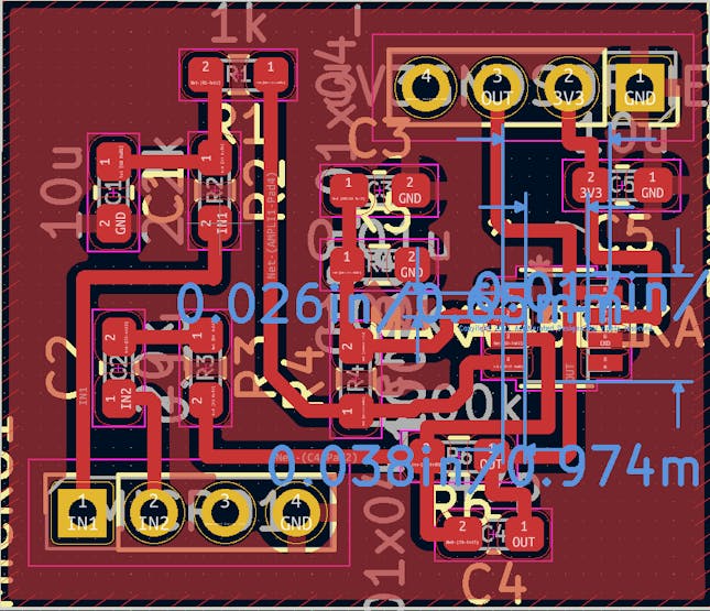
We also did a PCB for the Audio part, it include an MAX4468 Micropower
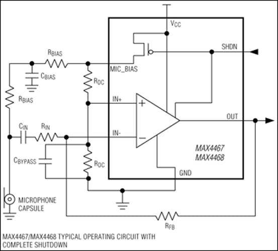
Our PCB included the MAX4468 Micropower amplifier to minimize noise and parasitic residues.
Here you can see our PCB with the Max4468 micropower
The initial circuit
Our PCB
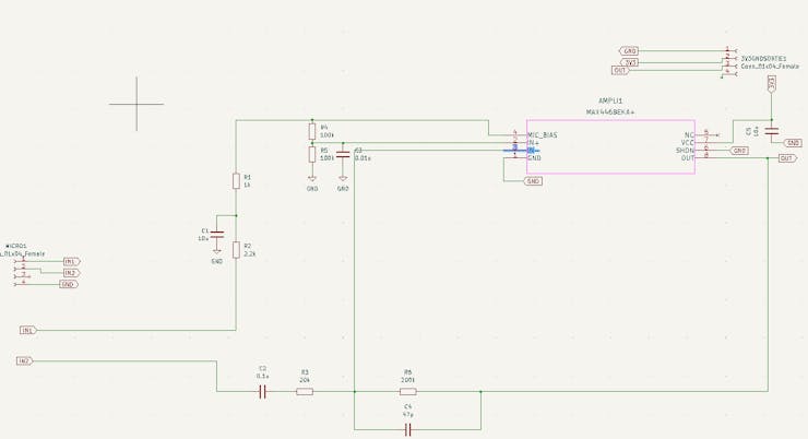
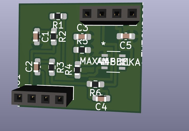
Once the PCB was completed, we proceeded to testing each sensor individually to ensure their accuracy and proper functioning. We used the example code gived by their libraries Next, we integrated the sensors with our microcontroller, and wrote code to properly collect and transmit the data collected.
We also analyzed the consumption of the latter using an Otii module, here is a quick tutorial : https://www.youtube.com/watch?v=bMf4I1TQzco
Simultaneously, we also worked on developing the enclosure for our system, using a waterproof PVC casing, that we drilled holes to run our sensor wires through. We then continued to test and refine the system as a whole, including debugging and making any necessary adjustments. Finally, we integrated our system with a data visualization platform, allowing for real-time monitoring of the hive and alerts to be sent in case of abnormal conditions. Throughout the project, we also collaborated closely with a professional beekeeper to ensure our system met the specific needs of the target market.
CODE EXPLANATION :
Initialization :
At the beginning of the code, you can see the initialization of our variables which must be global to be able to be changed by our functions and sent thanks to the LoRaWan protocol.
We also initialize the pins of our different sensors and include all the librairies
Functions : You have the lines so you can found this code in the attachments
1. LED ON

We used this function to put the arduino led on for 5 seconds when its starting to run
2. DHT 1 and 2

We are using the DHT library to get the humidity and the temperature from the DHT sensors.
We are adding doing 2 important things for the temperature :
1. Adding 100°C so the temperature will never be negative, thanks to this, there is no issue when being decoded in TTN
2. We do not send float because it is using too much data and short are easier to use, so we multiply it by 100 and we calibrate it with the minus 40.
Little exemple : imagine dht.readTemperature() = 20.48°C
tmp = (20.48+100)*100 -40 = 12 048 - 40 = 12 048
In TTN we are doing this : tmp = (tmp/100)-100 so we find our temperature
Here tmp = 20.48°C
Same thing for DHT2
3. MaximWire line 134
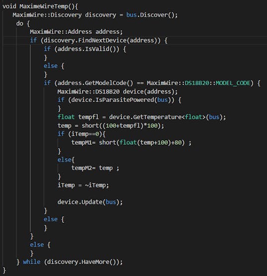
at first sight, there is no use for these conditions ( if(address.IsValid()...), let it because it is initialazing parameters for the dht.
we took the example code from the DHT library and we add 2 things :
the iTemp = ~iTemp imply that it will change from 1 to 0 and vice versa because the 2 MaximWire are connected the same pin, the first time you use GetTemperature, it will get the temperature from one sensor and the second time it will give you the temperature of the second sensor !
After, we did the same thing for the temperature as before and we calibrate it with a +80 (in reality, it add 0.8°C to the result)
4. Calibrate INA219

5. Luminosity INA219
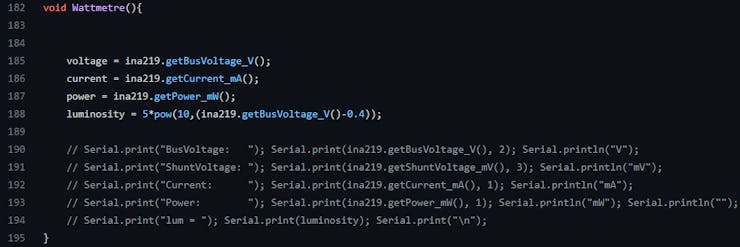
we are using the INA219 library so we get the voltage, the power and the current from our solar panel, we fond the mathematical form for luminosity in the documentation.
6. Battery
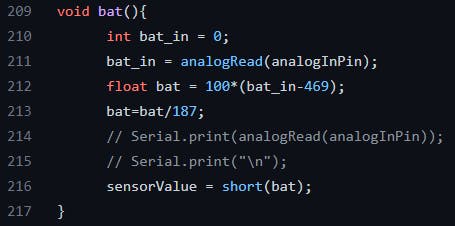
For the batterie, we get the voltage from the batterie and we used a voltage divider with 2 resistance because the battery can deliver a 4.2 V, it is too much for our arduino Uno.
Use resistance like 100k Ohms so it will bee efficiency and will not use a lot of current. get the tension divided by 2 and put it in an AnalogPin.
How an Analog pin work : it will convert the tension to a value. 3.3V is the max and Arduino will convert it to 1024.
Our battery go from 3V to 4.2V so our delta is 1.2V. Do not forget the divided by 2
So here, the max voltage gived to the pin will be 2.1V and the minimum will be 1.5V
2.1V converted become 652 and imply a 100% charged battery
1.5V converted become 466 and imply a 0% charged battery
Hyp : the battery charge will decrease linearly
So we find the battery percentage thanks to all this data !
7. Weight with HX711

We used the exemple from the HX711 library and changed the variables. We also calibrate it with the minus 38.77. There is a condition very important, we put the weight at 0 if it is too low so there is no negative weight.
8.FFT and microphone
Thanks to our PCB, we have our micro voltage in a pin.
We use an FFT to get the amplitude of each of our frequencies and we make an average of it for measurement ranges.
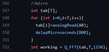
In the loop, we are creating a table of T sample and we put the micro value each 800 ms, it imply fmax = 1250Hz (with the Shanon factor, it is currently 625Hz)
Q_FFT equal 0 if it has not done well the FFT. It also run the code and put all the amplitude in a global table initialized in the start of the code.
9.Check response
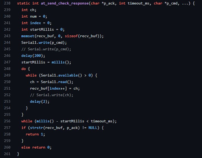
This code is given in the TTN tutorial, it check if a response is given by the network
10. Setup
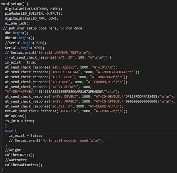
Initialize our sensors and the parameters for LoRaWAN and TTN.
IMPORTANT : USE YOUR TTN ID, KEY… Follow the tutorial !
11. Void LOOP
Test phase and connection to the network :
If we are connected, then we use our functions to update all our variables.
then we send them thanks to LoRaWAN.
Custom parts and enclosures
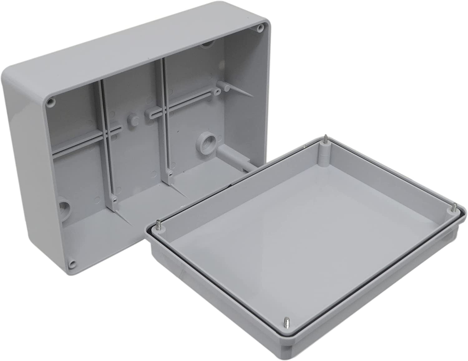
waterproof pvc box
We have chosen to use a waterproof PVC enclosure for our project, which we have drilled to fit in the cables of our sensors. This waterproof enclosure will protect our electronic components from external elements such as moisture or dust. Additionally, the sturdy PVC material of the enclosure will also protect the system from potential impact or collision.
Schematics
wiring diagram
The wiring diagram for our bee hive monitoring system is well-organized and easy to follow. The connections between the various components are clearly labeled and the layout is logical. The color coding used also helps to make it easy to identify the different wires and connections.、
Code
Main with french comment
C/C++
you can use this code and only change the pins you connected with your arduino.
Also, change the parameters for the lorawan uplink with your ttn acount parameters
#include <DHT.h>
#include <HX711.h>
#define MAXIMWIRE_EXTERNAL_PULLUP
#include <MaximWire.h>

//PIN DHT EXT
#define brocheBranchementDHT 6
#define typeDeDHT DHT22
//DHT INT
#define brocheBranchementDHTint 7

#define calibration_factor 20942.00 //This value is obtained using the SparkFun_HX711_Calibration sketch
//PINS HX711
#define LOADCELL_DOUT_PIN  D3
#define LOADCELL_SCK_PIN  D2

#define SHUTDOWN D11

//Wattmetre pour luminosité
#include <Wire.h>
#include "DFRobot_INA219.h"

//PIN température MaximWire
#define PIN_BUS 9
MaximWire::Bus bus(PIN_BUS);
MaximWire::DS18B20 device;

DHT dht(brocheBranchementDHT,typeDeDHT);
DHT dhtint(brocheBranchementDHTint,typeDeDHT);

HX711 scale;


//WattMetre
DFRobot_INA219_IIC     ina219(&Wire, INA219_I2C_ADDRESS4);
float ina219Reading_mA = 1000;
float extMeterReading_mA = 1000;

static char recv_buf[512];
static bool is_exist = false;
static bool is_join = false;
static int led = 0;
int ret=0;

//DHT
float tmpfl;
short tmp =20;
short hum=50;

//DHT int
float tmpflint;
short tmpint =20;
short humint=50;

//HX711
float massfl;
short mass;

//Température MaximeWire
int iTemp = 0;
short temp = 0;
short tempM1 = 0;
short tempM2 = 0;

//Pour le pourcentage de batterie
const int analogInPin = A1;  // Analog input pin that the potentiometer is attached to
short sensorValue = 0;        // value read from the pot

//Pour le WattMetre
float voltage = 0;
float current = 0;
float power = 0;
short luminosity =0;

//micro
#define T 64
int freq_amp[32][2];
short Amp[10];
int data[64]={14, 30, 35, 34, 34, 40, 46, 45, 30, 4,  -26,  -48,  -55,  -49,  -37,
-28,  -24,  -22,  -13,  6,  32, 55, 65, 57, 38, 17, 1,  -6, -11,  -19,  -34,
-51,  -61,  -56,  -35,  -7, 18, 32, 35, 34, 35, 41, 46, 43, 26, -2, -31,  -50,
-55,  -47,  -35,  -27,  -24,  -21,  -10,  11, 37, 58, 64, 55, 34, 13, -1, -7};
//fin micro

//downlink
int freqEnvoi = 600000;
char* down;
int down_int;
char* downlink;

void freq_envoi(){

  downlink= strstr(recv_buf,"\"");
  down = strtok(downlink,"\"");
  down_int = strtol(down,NULL,16);
  if(down_int>0 && down_int < 31){
        freqEnvoi = down_int*60000;
        //Serial.println("freq envoyé=");
        //Serial.println(freqEnvoi);
        delay(freqEnvoi);
      }
      else{
        //Serial.println("freq envoyé du else =");
        //Serial.println(freqEnvoi);
        delay(freqEnvoi);
      }
}

void allume_led() {
  digitalWrite(LED_BUILTIN, HIGH);
  delay(5000);
  digitalWrite(LED_BUILTIN, LOW);
}

void DHT1(){
    // Serial.print("\n ");
    hum = dht.readHumidity();
    tmpfl = dht.readTemperature()+100;
    tmp = short(tmpfl*100-40);
     //Serial.print("Humidité = "); Serial.print(hum); Serial.println(" %");
     //Serial.print("Température = "); Serial.print(tmpfl); Serial.println(" °C");
     //Serial.print("TempératureShort = "); Serial.print(tmp); Serial.println(" °C");
}

void DHT2(){
    // Serial.print("\n ");
    humint = dhtint.readHumidity();
    tmpflint = dhtint.readTemperature()+100;
    tmpint = short(tmpflint*100+80);
    // Serial.print("Humidité Intérieur = "); Serial.print(humint); Serial.println(" %");
    // Serial.print("Température Intérieur = "); Serial.print(tmpflint); Serial.println(" °C");
}

void MaximeWireTemp(){

   MaximWire::Discovery discovery = bus.Discover();
    do {
        MaximWire::Address address;
        if (discovery.FindNextDevice(address)) {
            // Serial.print("FOUND: ");
            // Serial.print(address.ToString());
            if (address.IsValid()) {
                // Serial.print(" (VALID)");
            } else {
                // Serial.print(" (INVALID)");
            }
            if (address.GetModelCode() == MaximWire::DS18B20::MODEL_CODE) {
                // Serial.print(" (DS18B20)");
                MaximWire::DS18B20 device(address);
                if (device.IsParasitePowered(bus)) {
                    // Serial.print(" (PARASITE POWER)");
                }
                float tempfl = device.GetTemperature<float>(bus);
                temp = short((100+tempfl)*100);

                if (iTemp==0){
                    tempM1= short(float(temp+100)+80) ;//* 0.0669;
                    //Serial.print(" temp1=");
                     //Serial.print(tempM1);
                    //Serial.print(" °C");
                    //Serial.println();
                }
                else{
                    tempM2= temp ;//* 0.06425;
                    //Serial.print(" temp2=");
                    //Serial.print(tempM2);
                    //Serial.print(" °C");
                    //Serial.println();
                }
                iTemp = ~iTemp;

                device.Update(bus);
            } else {
                // Serial.println();
            }
        } else {
            // Serial.println("NOTHING FOUND");
        }
    } while (discovery.HaveMore());
}

void Wattmetre(){


    voltage = ina219.getBusVoltage_V();
    current = ina219.getCurrent_mA();
    power = ina219.getPower_mW();
    luminosity = 5*pow(10,(ina219.getBusVoltage_V()-0.4));

    // Serial.print("BusVoltage:   "); Serial.print(ina219.getBusVoltage_V(), 2); Serial.println("V");
    // Serial.print("ShuntVoltage: "); Serial.print(ina219.getShuntVoltage_mV(), 3); Serial.println("mV");
    // Serial.print("Current:      "); Serial.print(ina219.getCurrent_mA(), 1); Serial.println("mA");
    // Serial.print("Power:        "); Serial.print(ina219.getPower_mW(), 1); Serial.println("mW"); Serial.println("");
    // Serial.print("lum = "); Serial.print(luminosity); Serial.print("\n");
}

void calibreWattmetre(){
  // Serial.println();
  //Initialize the sensor
  //while(ina219.begin() != true) {
  //  Serial.println("INA219 begin faild");
  //  delay(2000);
  //}
  //Linear calibration
  ina219.begin();
  ina219.linearCalibrate(/*The measured current before calibration*/ina219Reading_mA, /*The current measured by other current testers*/extMeterReading_mA);

}
void bat(){
      int bat_in = 0;
      bat_in = analogRead(analogInPin);
      float bat = 100*(bat_in-469);
      bat=bat/187;
      // Serial.print(analogRead(analogInPin));
      // Serial.print("\n");
      sensorValue = short(bat);
}
void HX711(){
    scale.power_up();
    // Serial.print("\n ");
    massfl = scale.get_units()-38.77;//scale.get_units() returns a float
    mass = short(massfl*100);
    if(massfl<=1){mass=0;}
    // Serial.print(massfl, 2);
    // Serial.println(" kg"); //You can change this to kg but you'll need to refactor the calibration_factor
    scale.power_down();
}

void calibreHX711(){
  // Serial.println("HX711 scale demo");
  scale.begin(LOADCELL_DOUT_PIN, LOADCELL_SCK_PIN);
  // Serial.println("DOUT et SCK OK");
  scale.set_scale(calibration_factor); //This value is obtained by using the SparkFun_HX711_Calibration sketch
  //scale.tare(); //Assuming there is no weight on the scale at start up, reset the scale to 0
  // Serial.println("Calibrage OK");
}

static int at_send_check_response(char *p_ack, int timeout_ms, char *p_cmd, ...) {
  int ch;
  int num = 0;
  int index = 0;
  int startMillis = 0;
  memset(recv_buf, 0, sizeof(recv_buf));
  Serial1.write(p_cmd);
  // Serial.write(p_cmd);
  delay(200);
  startMillis = millis();
  do {
    while (Serial1.available() > 0) {
      ch = Serial1.read();
      recv_buf[index++] = ch;
      // Serial.write(ch);
      delay(2);
    }
  }
  while (millis() - startMillis < timeout_ms);
  if (strstr(recv_buf, p_ack) != NULL) {
    return 1;
  }
  else return 0;
}

void setup() {
  digitalWrite(SHUTDOWN, HIGH);
  pinMode(LED_BUILTIN, OUTPUT);
  digitalWrite(LED_PWR, LOW);
  allume_led();
 // put your setup code here, to run once:
  dht.begin();
  dhtint.begin();
  //Serial.begin(9600);
  Serial1.begin(9600);
  // Serial.print("Serial1 LORAWAN TEST\r\n");
  if(at_send_check_response("+AT: OK", 100, "AT\r\n")) {
  is_exist = true;
  at_send_check_response("+ID: AppEui", 1000, "AT+ID\r\n");
  at_send_check_response("+MODE: LWOTAA", 1000, "AT+MODE=LWOTAA\r\n");
  at_send_check_response("+DR: EU868", 1000, "AT+DR=EU868\r\n");
  at_send_check_response("+CH: NUM", 1000, "AT+CH=NUM,0-2\r\n");
  at_send_check_response("+KEY: APPKEY", 1000,
  "AT+KEY=APPKEY,\"YOUR TTN KEY\"\r\n");
  at_send_check_response("+KEY: DEVEUI", 1000, "AT+ID=DEVEUI,\"YOUR TTN ID \"\r\n");
  at_send_check_response("+KEY: APPEUI", 1000, "AT+ID=APPEUI,\"0000000000000000\"\r\n");
  at_send_check_response("+CLASS: C", 1000, "AT+CLASS=A\r\n");
  ret=at_send_check_response("+PORT: 8", 1000, "AT+PORT=8\r\n");
  delay(200);
  is_join = true;
  }
  else {
    is_exist = false;
    // Serial.print("No Serial1 module found.\r\n");
  }

  //Capteur de poids
  calibreHX711();

  //WattMetre
  calibreWattmetre();

  // Serial.println("Readings:");
}

void loop() {
  if (is_exist) {
  int ret = 0;
    if (is_join) {
      ret = at_send_check_response("+JOIN: Network joined", 12000, "AT+JOIN\r\n");
      if (ret) {
        is_join = false;
        // Serial.println();
        // Serial.print("Network JOIN !\r\n\r\n");
      }
      else {
        at_send_check_response("+ID: AppEui", 1000, "AT+ID\r\n");
        // Serial.println();
        // Serial.print("JOIN failed!\r\n\r\n");
        delay(5000);
      }
    }
    else { //capteurs et envoie ubidots
      // Serial.print("Reading: ");

      //Capteur de poids
      HX711();

      //Capteur humidité et température DHT
      DHT1();
      DHT2();

      //Capteurs de température DS18B20 MaximWire
      // Serial.print("\n ");
      MaximeWireTemp();

      //Récupération de la tension délivrée par la batterie pour pourcentage
      // Serial.print("\n ");

      //sensorValue = static_cast<short>(100*analogRead(analogInPin)/630 - 3);
      bat();

      // Serial.print("sensor = "); // Serial.print(sensorValue); // Serial.print("%\n");

      //Recuperations des informations du wattmetre
      // Serial.print("\n ");
      Wattmetre();

      //micro
      int tab[T];
      for (int i=0;i<T;i++){
        tab[i]=analogRead(A0);
        delayMicroseconds(800);
      }
      int working = Q_FFT(tab,T,1250);

      //Communication avec ubidots

      char cmd[128];
      sprintf(cmd, "AT+MSGHEX=%04X%04X%04X%04X%04X%04X%04X%04X%04X%04X%04X%04X%04X%04X%04X%04X%04X%04X\r\n", tmpint, humint*100, mass, sensorValue, tempM1,
                                                        tempM2, tmp, Amp[0],Amp[1],Amp[2],Amp[3],Amp[4],Amp[5],Amp[6],Amp[7],Amp[8],Amp[9], luminosity);
      at_send_check_response("ACK Received", 5000, cmd);
      freq_envoi();
      //delay(2000);
    }
  }
  else {
    delay(1000);
  }
}
///////////////////////////////////////////////////////------------------        FFT         -----------------//////////////////////////////////////////////////////////////////


int Q_FFT(int in[],int N,float Frequency){

unsigned int Pow2[13]={1,2,4,8,16,32,64,128,256,512,1024,2048}; // declaring this as global array will save 1-2 ms of time


int a,c1,f,o,x;
byte check=0;
a=N;

      for(int i=0;i<12;i++)//calculating the levels
         { if(Pow2[i]<=a){o=i;} }

int out_r[Pow2[o]]={};   //real part of transform
int out_im[Pow2[o]]={};  //imaginory part of transform

x=0;
      for(int b=0;b<o;b++)                     // bit reversal
         {
          c1=Pow2[b];
          f=Pow2[o]/(c1+c1);
                for(int j=0;j<c1;j++)
                    {
                     x=x+1;
                     out_im[x]=out_im[j]+f;
                    }
         }


      for(int i=0;i<Pow2[o];i++)            // update input array as per bit reverse order
         {
          out_r[i]=in[out_im[i]];
          out_im[i]=0;
         }


int i10,i11,n1,tr,ti;
float e;
int c,s;
    for(int i=0;i<o;i++)                                    //fft
    {
     i10=Pow2[i];              // overall values of sine/cosine
     i11=Pow2[o]/Pow2[i+1];    // loop with similar sine cosine
     e=360/Pow2[i+1];
     e=0-e;
     n1=0;

          for(int j=0;j<i10;j++)
          {
            c=e*j;
  while(c<0){c=c+360;}
  while(c>360){c=c-360;}

          n1=j;

          for(int k=0;k<i11;k++)
                 {

       if(c==0) { tr=out_r[i10+n1];
                  ti=out_im[i10+n1];}
  else if(c==90){ tr= -out_im[i10+n1];
                  ti=out_r[i10+n1];}
  else if(c==180){tr=-out_r[i10+n1];
                  ti=-out_im[i10+n1];}
  else if(c==270){tr=out_im[i10+n1];
                  ti=-out_r[i10+n1];}
  else if(c==360){tr=out_r[i10+n1];
                  ti=out_im[i10+n1];}
  else if(c>0  && c<90)   {tr=out_r[i10+n1]-out_im[i10+n1];
                           ti=out_im[i10+n1]+out_r[i10+n1];}
  else if(c>90  && c<180) {tr=-out_r[i10+n1]-out_im[i10+n1];
                           ti=-out_im[i10+n1]+out_r[i10+n1];}
  else if(c>180 && c<270) {tr=-out_r[i10+n1]+out_im[i10+n1];
                           ti=-out_im[i10+n1]-out_r[i10+n1];}
  else if(c>270 && c<360) {tr=out_r[i10+n1]+out_im[i10+n1];
                           ti=out_im[i10+n1]-out_r[i10+n1];}

                 out_r[n1+i10]=out_r[n1]-tr;
                 out_r[n1]=out_r[n1]+tr;
                 if(out_r[n1]>15000 || out_r[n1]<-15000){check=1;}

                 out_im[n1+i10]=out_im[n1]-ti;
                 out_im[n1]=out_im[n1]+ti;
                 if(out_im[n1]>15000 || out_im[n1]<-15000){check=1;}

                 n1=n1+i10+i10;
                  }
             }

    if(check==1){                                             // scale the matrics if value higher than 15000 to prevent varible from overloading
                for(int i=0;i<Pow2[o];i++)
                    {
                     out_r[i]=out_r[i]/100;
                     out_im[i]=out_im[i]/100;
                    }
                     check=0;
                }

     }


//---> here onward out_r contains amplitude and our_in conntains frequency (Hz)
int fout,fm,fstp;
float fstep;
fstep=Frequency/N;
fstp=fstep;
fout=0;fm=0;

    for(int i=1;i<Pow2[o-1];i++)               // getting amplitude from compex number
        {
        if((out_r[i]>=0) && (out_im[i]>=0)){out_r[i]=out_r[i]+out_im[i];}
   else if((out_r[i]<=0) && (out_im[i]<=0)){out_r[i]=-out_r[i]-out_im[i];}
   else if((out_r[i]>=0) && (out_im[i]<=0)){out_r[i]=out_r[i]-out_im[i];}
   else if((out_r[i]<=0) && (out_im[i]>=0)){out_r[i]=-out_r[i]+out_im[i];}
   // to find peak sum of mod of real and imaginery part are considered to increase speed

out_im[i]=out_im[i-1]+fstp;
if (fout<out_r[i]){fm=i; fout=out_r[i];}
         freq_amp[i][0]=out_im[i];
         freq_amp[i][1]=40*out_r[i];
        }
Amp[0] = (freq_amp[5][1]+freq_amp[6][1]+freq_amp[7][1]+freq_amp[8][1])/4;
Amp[1] = (freq_amp[8][1]+freq_amp[9][1]+freq_amp[10][1])/3;
Amp[2] = (freq_amp[10][1]+freq_amp[11][1]+freq_amp[12][1]+freq_amp[13][1])/4;//247hz = 13
Amp[3] = (freq_amp[13][1]+freq_amp[14][1]+freq_amp[15][1])/3; // 15 = 285hz
Amp[4] = (freq_amp[16][1]+freq_amp[17][1]+freq_amp[18][1])/3; // 18 = 342hz
Amp[5] = (freq_amp[18][1]+freq_amp[19][1]+freq_amp[20][1])/3; // 20 = 380 hz
Amp[6] = (freq_amp[21][1]+freq_amp[22][1]+freq_amp[23][1])/3; // 23 = 437 hz
Amp[7] = (freq_amp[23][1]+freq_amp[24][1]+freq_amp[25][1])/3; // 25 = 475 hz
Amp[8] = (freq_amp[26][1]+freq_amp[27][1]+freq_amp[28][1])/3; // 28 = 532 hz
Amp[9] = (freq_amp[28][1]+freq_amp[29][1]+freq_amp[30][1]+freq_amp[31][1])/4; // 31 = 589 hz

float fa,fb,fc;
fa=out_r[fm-1];
fb=out_r[fm];
fc=out_r[fm+1];
fstep=(fa*(fm-1)+fb*fm+fc*(fm+1))/(fa+fb+fc);
float ff = (fstep*Frequency/N);
if (ff<=1) {return 0;}
else{ return 1;}
}
The article was first published in hackster, January 10, 2023
cr: https://www.hackster.io/walidsrb4/honey-guys-monitoring-of-a-bee-hive-476c12
author: walid bouchichit, Ilyes ELBAHRI, Yacine Oulié, Adam K.


