
Use an ESP32 to control anything from stepper motors to LED strips with easy-to-use and modular code. It can connect locally or externally.
Software apps and online services
- Autodesk Fusion 360
- EagleCAD
- Microsoft VS Code
- Arduino IDE
Hand tools and fabrication machines
- 3D Printer (generic)
- Soldering iron (generic)
Story
Idea
Creating a system that can handle large amounts of sensor data, have multiple outputs, and connect to the internet or a local network takes a long time and large amounts of effort. All too often, people wanting to make their own smart home networks struggle with being able to find and assemble custom components into a larger system. That is why I wanted to make a modular and feature-rich platform that would make it easy to construct IoT-connected sensors and outputs.
Thanks to DFRobot and PCBGOGO.com for sponsoring this project!
For more in-depth information, visit the github repo: https://github.com/having11/Smart_Home_Hub
Features
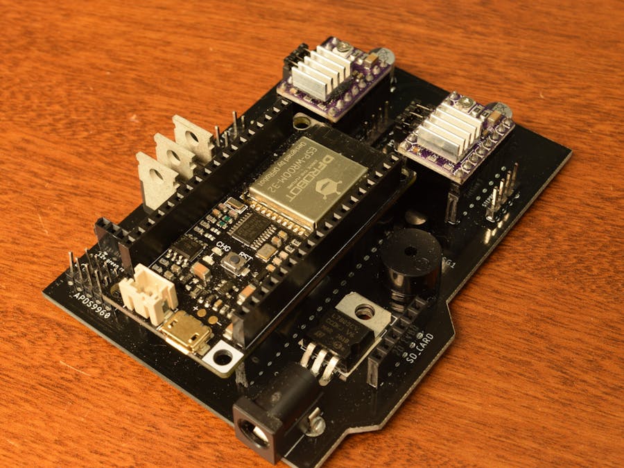
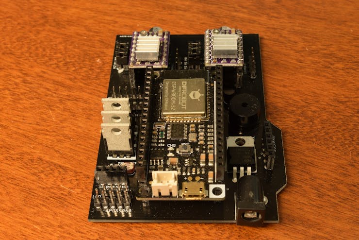
The main feature of this board is an ESP32 FireBeetle Development Board that handles all communication, sensor readings, and outputs. There are two stepper motor drivers that control two bipolar stepper motors.
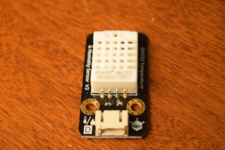
The I2C bus is also broken out for use with components such as the APDS9960 or an LCD. For reading the temperature, there are pins broken to connect to a DHT22 sensor, as well as a photoresistor for reading ambient light levels.
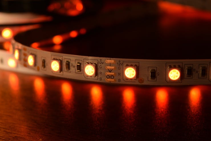
There is support for an analog light strip on the board, which has three MOSFETs on it to drive the LED lights.
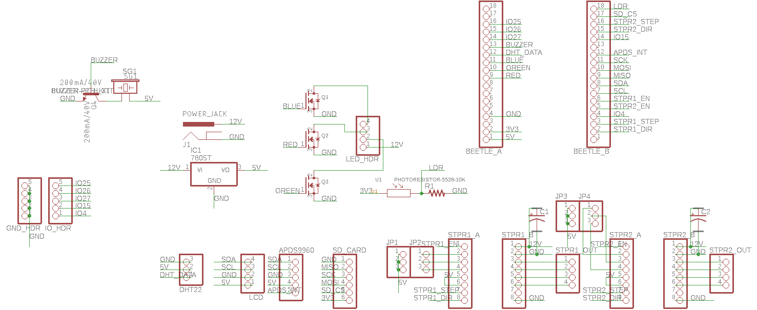
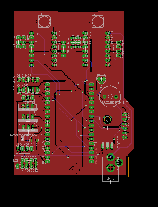
PCB
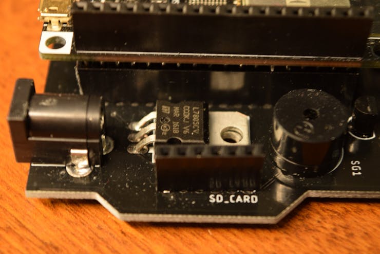
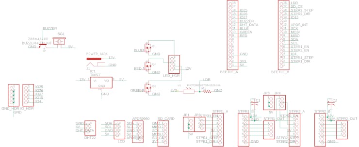
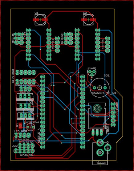
I began the PCB design process by first creating a schematic in Eagle. Since I was unable to find an ESP32 FireBeetle library, I just used two pin 1x18 pin headers instead. Then, I created a power management circuit that could accept 12v through a DC barrel jack and convert it to 5v for powering the sensors and ESP32.
After the schematic was completed, I moved onto designing the PCB itself.
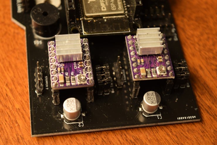
I knew that the DC barrel plug would have to be near the front of the board, and the 100uF power supply smoothing capacitors needed to be close to the stepper motor driver power inputs. After everything was laid out, I started to route traces.
While OSHPark makes great quality PCBs, their prices are quite high. Thankfully, PCBGOGO.com also makes great PCBs at an affordable price. I was able to buy ten PCBs for just $5, rather than paying $52 for just three boards from OSHPark.com.
Assembly
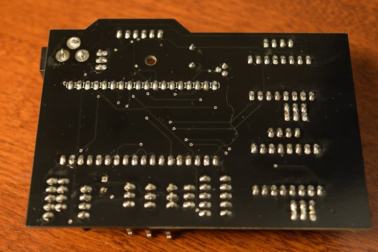
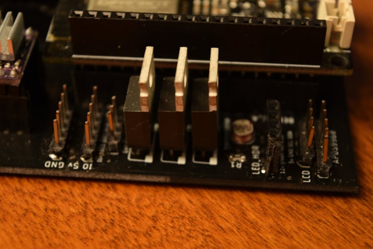
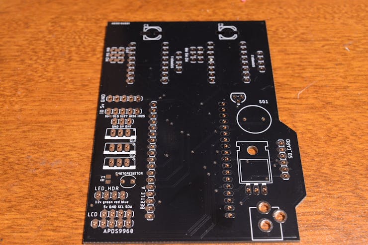
Overall, assembling the board was quite easy. I started by soldering the surface mounted components, and then attaching the barrel jack connector and regulator. Next, I soldered in the pin headers for components such as the motor drivers and the FireBeetle.
After soldering had been completed, I tested the board for short circuit by putting a multimeter into resistance-measuring mode and seeing if the resistance was over a certain amount. The board passed, so I was then able to plug in each component.
Programming Overview
I wanted the code for this board to be modular and easy to use. This meant having several classes that handle specific functions, along with a larger wrapper class that combines the smaller ones.
Inputs
For handling inputs, I created a class called “Hub_Inputs”, which lets the home hub communicate with the APDS9960, along with creating and managing buttons and capacitive touch interfaces. It contains the following functions:
- Create button- Get if button is pressed- Get number of button presses- Get latest gesture- Get capacitive touch value
The buttons are stored as a struct, with three attributes: is_pressed, numberPresses, and pin. Each button, when created, is attached to an interrupt. When that interrupt is triggered, the Interrupt Service Routine (ISR) is passed that button’s pointer (given as the memory address of it in the button array) and increments the number of button presses, along with updating the is_pressed Boolean value.
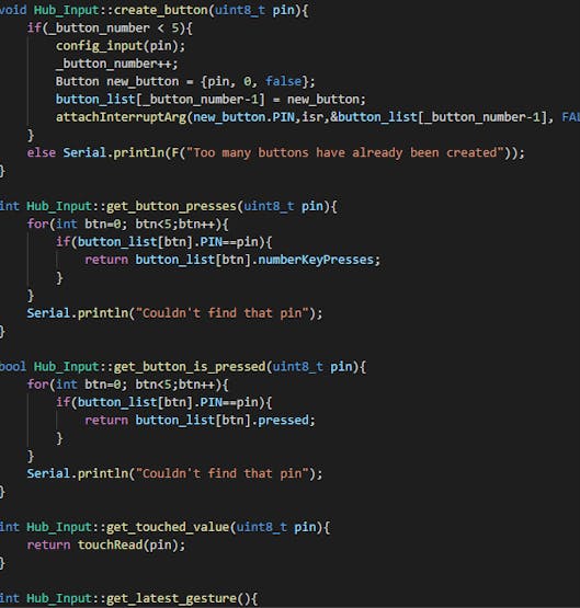
Capacitive touch values are much simpler. They are retrieved by passing the touch pin to the touchRead() function.
The latest gesture is updated by polling the APDS9960 and checking if any new gesture has been detected, and if one has been detected, set the private gesture variable to that gesture.
Outputs
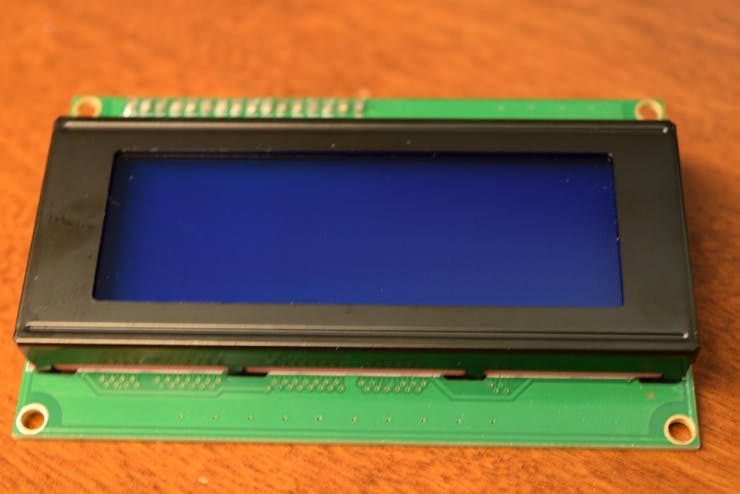
The smart home hub features several ways to output information and change lights. There are pins that break out the I2C bus, letting users connect an LCD. SO far, only one size of LCD is supported: 20 x 4. By using the function “hub.display_message()”, users can display messages on the LCD by passing in a string object.
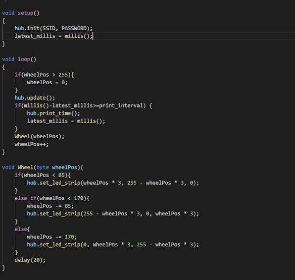
There is also a pin header to connect a string of analog LEDs. Calling the function “hub.set_led_strip(r, g, b)”, sets the color of the strip.
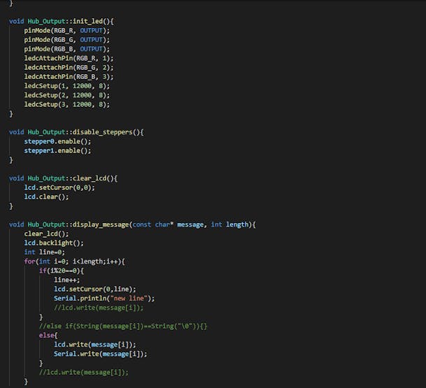


The two stepper motors are driven using a pair of DRV8825 driver boards. I decided to use the BasicStepper library to handle motor control. When the board is booted up, two stepper objects are created, and both motors become enabled. To step each motor, the “hub.step_motor(motor_id, steps)” function is used, where motor id is either 0 or 1.
Logging
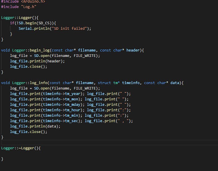
Because the board has several sensors, I wanted the ability to locally collect and log data.
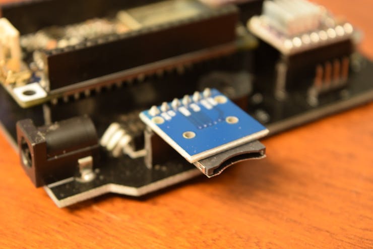
To start logging, a new file is created with “hub.create_log(filename, header)”, where header is used to make a CSV file row that denotes columns. The first column is always a timestamp in Year Month Day Hour:Min:Sec format. To get the time, the hub.log_to_file() function gets the time with the basic_functions.get_time() function. The tm time struct is then passed by reference into the logging function, along with the data and filename.
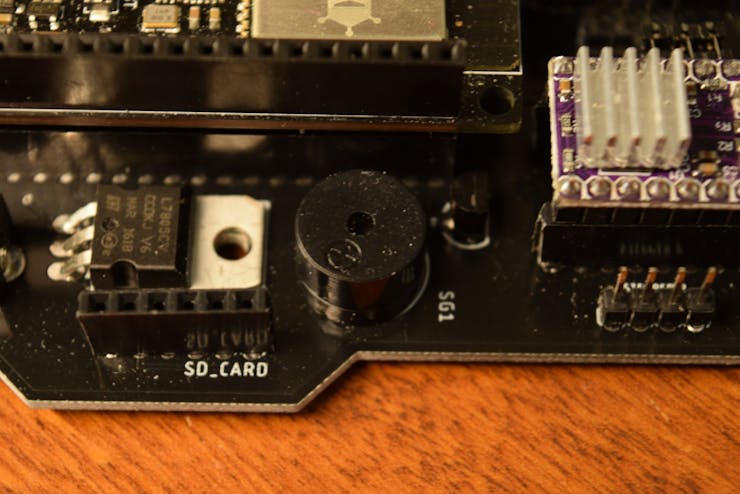
Buzzer
What good is an IoT board if you can’t play music? That’s why I included a buzzer with a function to play sounds. Calling “hub.play_sounds(melody, duration, length)” starts to play a song, with melody being an array of note frequencies, duration as an array of note durations, and length as the number of notes.
External IoT Integrations
The hub currently supports IFTTT webhooks. They can be triggered by calling the Hub_IoT.publish_webhook(url, data, event, key) or Hub_IoT.publish_webhook(url, data) function. This sends a POST request to the given URL with that data attached, along with an event name if necessary.
To setup an example IFTTT integration, first create a new applet. Then select the webhook service that triggers when a request is received.
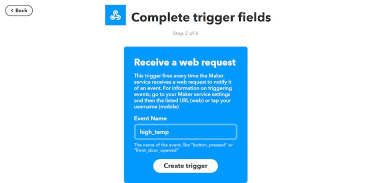
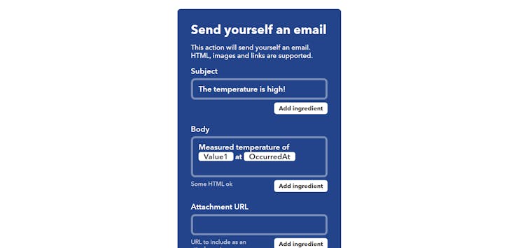
Next, call the event “high_temp” and save it. Then, select the Gmail service for the “That” part, and choose “Send an email to myself” option. Within the setup for the service, put “The temperature is high!” for the subject, and then I put “Measured temperature of {{Value1}} at {{OccurredAt}}”, which shows the measured temperature and the time when the event was triggered.
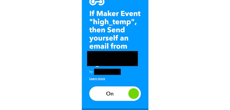
After setting it up, simply paste the webhook URL that is generated by IFTTT, and putting “high_temp” in the event section.
Usage
To use the smart home hub, simply call any needed functions in either setup() or loop(). I have already put example function calls, such as printing the current time and calling an IFTTT event.
Future Plans
The smart home hub system works very well for simple home automation and data collection tasks. It can be used for almost anything, such as setting the color of an LED strip, monitoring the temperature of a room, checking if a light’s on, and a whole host of other potential projects. In the future, I would like to expand the functionality even more. This could include adding a more robust webserver, local file hosting, and even Bluetooth or MQTT.
Schematic
Board
Code
This article was first published in Hackster, on July 1, 2019
cr: https://www.hackster.io/gatoninja236/esp32-smart-home-hub-6e8049
Author: Evan Rust


