Our HaBeeBee Monitoring System allows the managing and monitoring beehives making life easier for beekeepers.
Things used in this project
Hardware components
Software apps and online services
Beep
The Things Network [https://www.hackster.io/the-things-network/products/the-things-network?ref=project-c5267e]
Story
Introduction
Bees are key pollinating insects for the environment, but they face many dangers that can affect their health and survival. Bees may face:
Predators: Some species of animals may attack or raid hives in search of food. Hive theft: Sometimes beekeepers discover that their hive has been stolen. Pesticides: they can be dangerous to bees because they can kill or weaken insects that feed on flowers. Environment: They can be affected by a number of environmental factors, such as temperature and humidity fluctuations and air pollution.
It is important to take measures to protect bees and ensure their long-term survival. Therefore, we propose a monitoring system using microcontrollers and sensors can help beekeepers to better understand and protect their beehives.
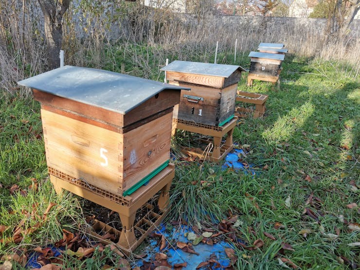
The system consists of different sensors:
Humidity/temperature DHT22 x2 Temperature DS18B20 x2 Weight HX711 x1 Light intensity SEN0291 x1 Sound x1
It is composed of a battery and a solar panel. The device also contains a LiPo Rider Pro card that makes the link between the two components, making it energy self-sufficient.
System Setup
Sensor
First of all, each component is tested individually in order to verify their proper functioning. To realize this step, a protoboard, microcontroller and a sensor are used. It will be necessary to put the specific code of the sensor in the microcontroller.
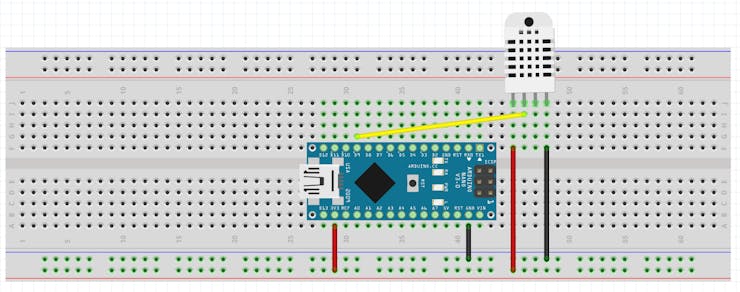
Wiring diagram for testing the DHT22 temperature and humidity sensor
The same must be done with all the sensors (DS18B20, HX711, SEN0291). For the connection and testing of these sensors, refer to the component links in the description.
After having tested all of them, we made a general code to have the information of all of it at the same time (ours is in description at the end of the article)
Microphone
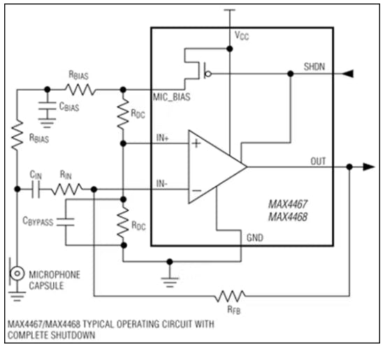
In order to study the behavior of the bees, we had to amplify the signal from the microphone. You have to follow the schematic to use the MAX4468 audio amplifier (you can find the document of the component on internet).
You must first test on protoboard and examine the signals on the oscilloscope to verify the proper functioning. However, there can be a lot of noise, which is obvious. So you will have to print the PCB of the audio circuit to get the right results.
Data transmission
Then, the LoRa-E5 module is used to transmit wirelessly the data. This information is sent to a server (TTN) which sends it to a Cloud (Ubidots). The Cloud allows to visualize the data on graphs. To use the module and send data to the server, go to the following link: https://wiki.seeedstudio.com/Grove_LoRa_E5_New_Version/
Finally, to link the TTN server with Ubidots, refer to this link: https://help.ubidots.com/en/articles/5096476-plugins-connect-the-things-stack-to-ubidots
Once on Ubidots, in order to execute our code, we will have to create the different variables and write the code below in the decoder part of the Plugins section.
function format_payload(args){
var ubidots_payload = {};
// Log received data for debugging purposes:
// console.log(JSON.stringify(args));
// Get RSSI and SNR variables using gateways data:
var gateways = args['uplink_message']['rx_metadata'];
for (const i in gateways) {
// Get gateway EUI and name
var gw = gateways[i];
var gw_eui = gw['gateway_ids']['eui'];
var gw_id = gw['gateway_ids']['gateway_id'];
// Build RSSI and SNR variables
ubidots_payload['rssi-' + gw_id] = {
"value": gw['rssi'],
"context": {
"channel_index": gw['channel_index'],
"channel_rssi": gw['channel_rssi'],
"gw_eui": gw_eui,
"gw_id": gw_id,
"uplink_token": gw['uplink_token']
}
}
ubidots_payload['snr-' + gw_id] = gw['snr'];
}
// Get Fcnt and Port variables:
ubidots_payload['f_cnt'] = args['uplink_message']['f_cnt'];
ubidots_payload['f_port'] = args['uplink_message']['f_port'];
// Get uplink's timestamp
ubidots_payload['timestamp'] = new Date(args['uplink_message']['received_at']).getTime();
// If you're already decoding in TTS using payload formatters,
// then uncomment the following line to use "uplink_message.decoded_payload".
// PROTIP: Make sure the incoming decoded payload is an Ubidots-compatible JSON (See https://ubidots.com/docs/hw/#sending-data)
// var decoded_payload = args['uplink_message']['decoded_payload'];
// By default, this plugin uses "uplink_message.frm_payload" and sends it to the decoding function "decodeUplink".
// For more vendor-specific decoders, check out https://github.com/TheThingsNetwork/lorawan-devices/tree/master/vendor
let bytes =  Buffer.from(args['uplink_message']['frm_payload'], 'base64');
var decoded_payload = decodeUplink(bytes)['data'];
// Merge decoded payload into Ubidots payload
Object.assign(ubidots_payload, decoded_payload);
return ubidots_payload
}
function decodeUplink(bytes) {
// Decoder for the RAK1906 WisBlock Environmental Sensor (https://store.rakwireless.com/products/rak1906-bme680-environment-sensor)
var decoded = {};
//if (bytes[0] == 1) {
// If received data is of Environment Monitoring type
decoded.temperature =  (bytes[0]<<8|bytes[1])/10 ;
decoded.humidity = (bytes[2]<<8|bytes[3]) ;
decoded.temp1 = (bytes[4]<<8|bytes[5])/10;
decoded.temp2 = (bytes[6]<<8|bytes[7])/10;
decoded.poids = (bytes[8]<<8|bytes[9])/100;
decoded.battery=(bytes[10]<<8|bytes[11])/100;
decoded.luminosity=bytes[12]<<8|bytes[13];
return {"data": decoded};
}
module.exports = { format_payload };
Don't forget to replace the values of AppEUI, DevEUI and AppKey from our code with yours that you put on TTN.
if(at_send_check_response("+AT: OK", 100, "AT\r\n")){
is_exist = true;
at_send_check_response("+ID: AppEui", 1000, "AT+ID\r\n");
at_send_check_response("+MODE: LWOTAA", 1000, "AT+MODE=LWOTAA\r\n");
at_send_check_response("+DR: EU868", 1000, "AT+DR=EU868\r\n");
at_send_check_response("+CH: NUM", 1000, "AT+CH=NUM,0-2\r\n");
at_send_check_response("+KEY: APPKEY", 1000, "AT+KEY=APPKEY,\"E2615C4277914656365B2A0F5F012047\"\r\n"); CHANGER HERE
at_send_check_response("+ID: DEVEUI", 1000, "AT+ID=DEVEUI,\"ABCDEF123456789A\"\r\n"); CHANGE HERE
at_send_check_response("+ID: APPEUI", 1000, "AT+ID=APPEUI,\"0000000000000000\"\r\n"); CHANGE HERE
at_send_check_response("+CLASS: C", 1000, "AT+CLASS=A\r\n");
ret=at_send_check_response("+PORT: 9", 1000, "AT+PORT=9\r\n");
delay(200);
is_join = true;
Check that the pins assigned in the code are the same as those physically assigned to the microcontroller. Everything is ready! The system is functional and can be launched.
Improvement
To make the system more compact, wire-free and to avoid noise, we replaced the protoboard with a PCB circuit from the KiCad software. First there is a PCB for the audio with the audio amplifier.
Now create the schematic and the footprint in KiCad so you can print it.
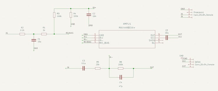
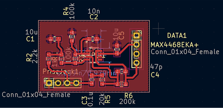
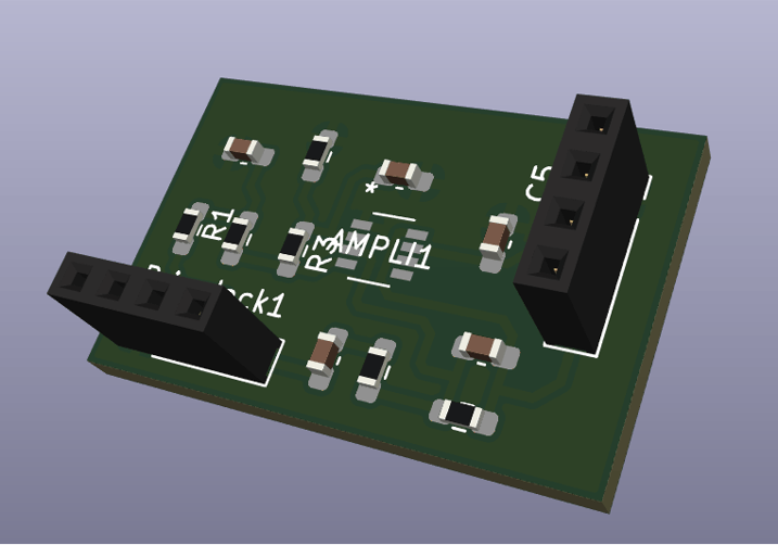
After printing the PCB, you have to solder the components (the audio amplifier, the resistors, the capacitors) on the PCB taking care to choose the right values of resistors and capacitors.
Then you have to create the final PCB which will contain the Arduino board and the connectors to link all the sensors.
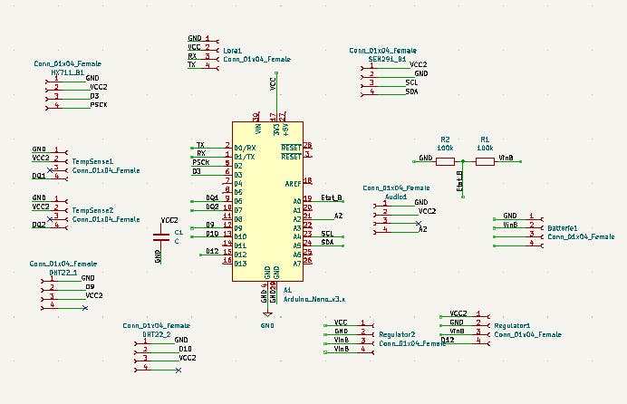
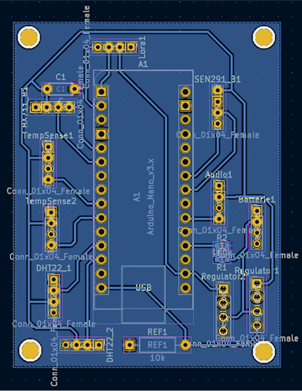
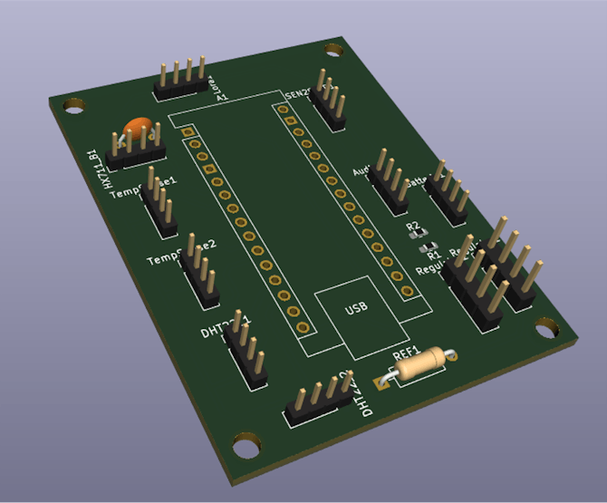
Building the system
Then we make our system waterproof to protect it from weather conditions. All modules or sensors were placed in a waterproof box. The sensors were extended with cables to be placed in/on the hive.
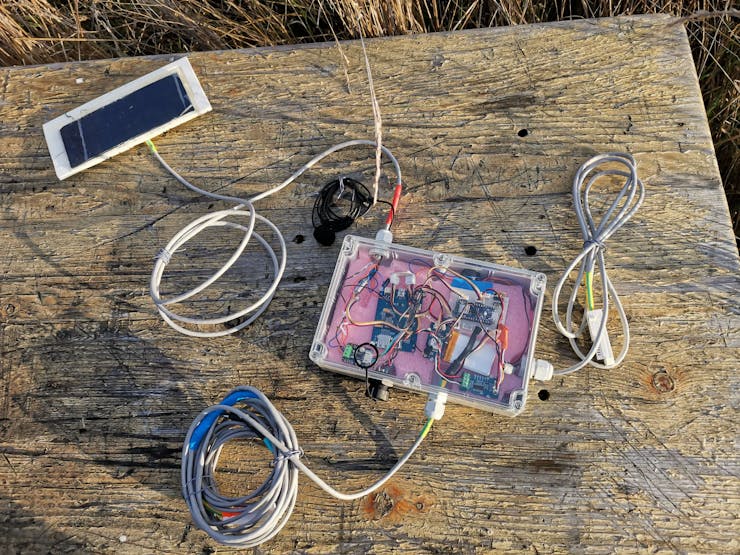
The box is functional and just needs to be tested!
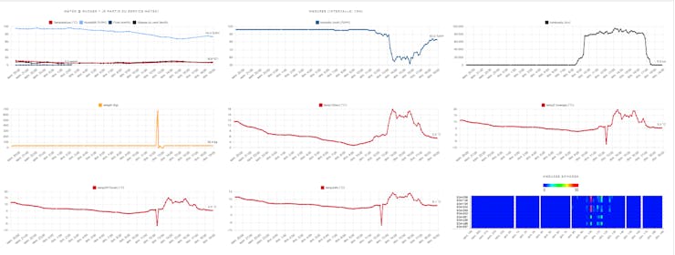
We decided to post our results on another Cloud, Beep. Here are the results we get.
You can find here our project presentation video.
Schematics
Final PCB
Code
Final Code
Arduino
#include <DHT.h>

#define MAXIMWIRE_EXTERNAL_PULLUP
#include "HX711.h"
#include <Wire.h>
#include <MaximWire.h>
#include "DFRobot_INA219.h"


#define PIN_BUS 7

#define calibration_factor -22072.0

#define LOADCELL_DOUT_PIN  D3
#define LOADCELL_SCK_PIN  D2

HX711 scale;

MaximWire::Bus bus(PIN_BUS);
MaximWire::DS18B20 device;


#define DHTPIN D9
#define DHTPIN1 D10

#define DHTTYPE DHT22
DHT dht(DHTPIN, DHTTYPE);
DHT dht1(DHTPIN1, DHTTYPE);
DFRobot_INA219_IIC     ina219(&Wire, INA219_I2C_ADDRESS4);

float ina219Reading_mA = 1000;
float extMeterReading_mA = 1000;

const float TensionMax =4.2;
const float TensionMin =3.3;
float masse=0.0;
static char recv_buf[512];
static bool is_exist = false;
static bool is_join = false;
static int led = 0;
int ret=0;
int delay_min = 1;
float tmp =20;
float hum=50;
float tmp1 =20;
float hum1=50;
float moyenne[10]={0,0,0,0,0,0,0,0,0,0};
int flag=0;
short masse_n=0;
short flag_temp=0;


float temp[2]={2,2};

#define T 64
int data[64]={14, 30, 35, 34, 34, 40, 46, 45, 30, 4,  -26,  -48,  -55,  -49,  -37,
-28,  -24,  -22,  -13,  6,  32, 55, 65, 57, 38, 17, 1,  -6, -11,  -19,  -34,
-51,  -61,  -56,  -35,  -7, 18, 32, 35, 34, 35, 41, 46, 43, 26, -2, -31,  -50,
-55,  -47,  -35,  -27,  -24,  -21,  -10,  11, 37, 58, 64, 55, 34, 13, -1, -7};


int freqd[10]={98,146,195,244,293,342,391,439,488,537};
int freqf[10]={146,195,244,293,342,391,439,488,537,586};

int cpt=0;
static int at_send_check_response(char *p_ack, int timeout_ms, char *p_cmd, ...){
  int ch;
  int num = 0;
  int index = 0;
  int startMillis = 0;
  memset(recv_buf, 0, sizeof(recv_buf));
  Serial1.write(p_cmd);
  //Serial.write(p_cmd);
  dht.begin();
  dht1.begin();
  delay(200);
  startMillis = millis();
  do{
    while (Serial1.available() > 0){
      ch = Serial1.read();

recv_buf[index++] = ch;
      //Serial.write(ch);
      delay(2);
    }
  } while (millis() - startMillis < timeout_ms);

  if (strstr(recv_buf, p_ack) != NULL){return 1;}
  else return 0;
}


void setup() {
 // put your setup code here, to run once:
  delay(10000);
  //Serial.begin(9600);
  Serial1.begin(9600);
  pinMode(12,OUTPUT);
  digitalWrite(D12,HIGH);
  pinMode(LED_BUILTIN, OUTPUT);
  digitalWrite(PIN_ENABLE_SENSORS_3V3, LOW);
  digitalWrite(PIN_ENABLE_I2C_PULLUP, LOW);

  scale.begin(LOADCELL_DOUT_PIN, LOADCELL_SCK_PIN);
  scale.set_scale(calibration_factor); //This value is obtained by using the SparkFun_HX711_Calibration sketch
  //scale.tare(); //Assuming there is no weight on the scale at start up, reset the scale to 0

  //Serial.print("E5 LORAWAN TEST\r\n");
  if(at_send_check_response("+AT: OK", 100, "AT\r\n")){
    is_exist = true;
    at_send_check_response("+ID: AppEui", 1000, "AT+ID\r\n");
    at_send_check_response("+MODE: LWOTAA", 1000, "AT+MODE=LWOTAA\r\n");
    at_send_check_response("+DR: EU868", 1000, "AT+DR=EU868\r\n");
    at_send_check_response("+CH: NUM", 1000, "AT+CH=NUM,0-2\r\n");
    at_send_check_response("+KEY: APPKEY", 1000, "AT+KEY=APPKEY,\"E2615C4277914656365B2A0F5F012047\"\r\n");
    at_send_check_response("+ID: DEVEUI", 1000, "AT+ID=DEVEUI,\"ABCDEF123456789A\"\r\n");
    at_send_check_response("+ID: APPEUI", 1000, "AT+ID=APPEUI,\"0000000000000000\"\r\n");
    at_send_check_response("+CLASS: C", 1000, "AT+CLASS=A\r\n");
    ret=at_send_check_response("+PORT: 9", 1000, "AT+PORT=9\r\n");
    delay(200);
    is_join = true;


  }
  else{
    is_exist = false;
    //Serial.print("No E5 module found.\r\n");
  }


  /*Config capteur intensité*/
   /*while(!Serial);

    Serial.println();
    while(ina219.begin() != true) {
        Serial.println("INA219 begin faild");
        delay(2000);
    }*/
    ina219.begin();
    delay(2000);
    ina219.linearCalibrate(ina219Reading_mA, extMeterReading_mA);
    //Serial.println();
}

void loop() {
  digitalWrite(D12,HIGH);
  digitalWrite(LED_PWR, HIGH);
  /* Poids, DHT:temperature et humidité*/
  flag=0;
  flag_temp=0;
  delay(1000);
  scale.power_up();
  //masse=scale.get_units();
  if (scale.get_units()-1<0)
    flag=1;
  delay(1000);
  hum = dht.readHumidity();
  tmp = dht.readTemperature();
  hum1= dht1.readHumidity();
  tmp1= dht1.readTemperature();
  //Serial.println(tmp);
  //Serial.println(hum);
  if (tmp<0)
  {
    flag_temp|=1<<1;
    tmp=abs(tmp);
  }
  if (tmp1<0)
  {
    flag_temp|=1<<4;
    tmp1=abs(tmp1);
  }
  delay(5000);

  /*FFT*/


  int i = 0;
  int tab[T];
  for (i=0;i<T;i++){
    tab[i]=analogRead(A2);
    delayMicroseconds(500);
  }
  unsigned long StartTime= micros();
  float f=Q_FFT(tab,T,2000);
  unsigned long CurrentTime= micros();
  unsigned long ElapsedTime= CurrentTime - StartTime;

  delay(1000);


  /* Etat batterie */
  float a0= analogRead(A0);
  float bat= a0*5/1523;


  delay(1000);

  /* Code intensité "lumineuse" */
  float Power = ina219.getPower_mW();
  //float Power=1;

 float intensity=ina219.getCurrent_mA();

  if(intensity<0)
    intensity=0;

  /*Intensité max pour environ 200mA*/

  /*Temperature DS18B20 */
  MaximWire::Discovery discovery = bus.Discover();
  do {
        MaximWire::Address address;
        if (discovery.FindNextDevice(address)) {
            if (address.GetModelCode() == MaximWire::DS18B20::MODEL_CODE) {

                MaximWire::DS18B20 device(address);
                temp[cpt] = device.GetTemperature<float>(bus);
                device.Update(bus);
            }
        }
        if (cpt==1)
          cpt=0;
        else
          cpt++;
    } while (discovery.HaveMore());

   if (temp[0]<0)
  {
    flag_temp|=1<<2;
    temp[0]=abs(temp[0]);
  }
 if (temp[1]<0)
  {
    flag_temp|=1<<3;
    temp[1]=abs(temp[1]);
  }
    /*Serial.println(temp[0]);
    Serial.println(temp[1]);
    Serial.println(tmp1);
    Serial.println(hum1);
    Serial.print("Reading: ");
    Serial.print(scale.get_units(), 2); //scale.get_units() returns a float
    Serial.println(" kg"); //You can change this to kg but you'll need to refactor the calibration_factor
    Serial.print("Poids:");
    Serial.println(masse);*/

  if (is_exist){

    int ret = 0;

    if (is_join){

      ret = at_send_check_response("+JOIN: Network joined", 12000, "AT+JOIN\r\n");

      if (ret){
        is_join = false;

        /*Serial.println();
        Serial.print("Network JOIN !\r\n\r\n");*/

      }

      else{
        at_send_check_response("+ID: AppEui", 1000, "AT+ID\r\n");
        /*Serial.println();
        Serial.print("JOIN failed!\r\n\r\n");*/
        delay(3000);
      }
    }
    else{

      char cmd[128];


      for(int i=0;i<10;i++)
      {
        //Serial.println(moyenne[i]);
      }
          if (!flag)
          {
            sprintf(cmd, "AT+MSGHEX=%04X%04X%04X%04X%04X%04X%04X%04X%04X%04X%04X%04X%04X%04X%04X%04X%04X%04X%04X%04X\r\n",(short) ((tmp*100)/10),(short) hum*100,(short)((temp[0]*100)/10),(short)((temp[1]*100)/10),(short) (2*bat*100),(short)(ina219.getBusVoltage_V()*100),(short)moyenne[0],(short)moyenne[1],(short)moyenne[2],(short)moyenne[3],(short)moyenne[4],(short)moyenne[5],(short)moyenne[6],(short)moyenne[7],(short)moyenne[8],(short)moyenne[9],(short) ((tmp1*100)/10),(short) hum1*100,(short)((scale.get_units()-1)*100),flag_temp); /* Résolution de 0.1°C*/
            at_send_check_response("ACK Received", 5000, cmd);
            digitalWrite(LED_PWR, LOW);
            scale.power_down();
          }
          else
          {
            sprintf(cmd, "AT+MSGHEX=%04X%04X%04X%04X%04X%04X%04X%04X%04X%04X%04X%04X%04X%04X%04X%04X%04X%04X%04X%04X\r\n",(short) ((tmp*100)/10),(short) hum*100,(short)((temp[0]*100)/10),(short)((temp[1]*100)/10),(short) (2*bat*100),(short)(ina219.getBusVoltage_V()*100),(short)moyenne[0],(short)moyenne[1],(short)moyenne[2],(short)moyenne[3],(short)moyenne[4],(short)moyenne[5],(short)moyenne[6],(short)moyenne[7],(short)moyenne[8],(short)moyenne[9],(short) ((tmp1*100)/10),(short) hum1*100,masse_n,flag_temp); /* Résolution de 0.1°C*/
            at_send_check_response("ACK Received", 5000, cmd);
            scale.power_down();
            digitalWrite(LED_PWR, LOW);
          }

    }
  }


  else{delay(1000);}
  delay(600000);

 /* char* downlink = strstr(recv_buf, "\"");
      downlink = strtok(downlink, "\"");
      if (downlink) delay_min = strtol(downlink, NULL, 16);
      if (delay_min < 1) delay_min = 1;
      if (delay_min > 60) delay_min = 60;
      delay(delay_min*60000);*/

}


float Q_FFT(int in[],int N,float Frequency)
{

unsigned int Pow2[13]={1,2,4,8,16,32,64,128,256,512,1024,2048}; // declaring this as global array will save 1-2 ms of time


int a,c1,f,o,x;
byte check=0;
a=N;

      for(int i=0;i<12;i++)                 //calculating the levels
         { if(Pow2[i]<=a){o=i;} }

int out_r[Pow2[o]]={};   //real part of transform
int out_im[Pow2[o]]={};  //imaginory part of transform

x=0;
      for(int b=0;b<o;b++)                     // bit reversal
         {
          c1=Pow2[b];
          f=Pow2[o]/(c1+c1);
                for(int j=0;j<c1;j++)
                    {
                     x=x+1;
                     out_im[x]=out_im[j]+f;
                    }
         }


      for(int i=0;i<Pow2[o];i++)            // update input array as per bit reverse order
         {
          out_r[i]=in[out_im[i]];
          out_im[i]=0;
         }


int i10,i11,n1,tr,ti;
float e;
int c,s;
    for(int i=0;i<o;i++)                                    //fft
    {
     i10=Pow2[i];              // overall values of sine/cosine
     i11=Pow2[o]/Pow2[i+1];
     e=360/Pow2[i+1];
     e=0-e;
     n1=0;

          for(int j=0;j<i10;j++)
          {
            c=e*j;
  while(c<0){c=c+360;}
  while(c>360){c=c-360;}

          n1=j;

          for(int k=0;k<i11;k++)
                 {

       if(c==0) { tr=out_r[i10+n1];
                  ti=out_im[i10+n1];}
  else if(c==90){ tr= -out_im[i10+n1];
                  ti=out_r[i10+n1];}
  else if(c==180){tr=-out_r[i10+n1];
                  ti=-out_im[i10+n1];}
  else if(c==270){tr=out_im[i10+n1];
                  ti=-out_r[i10+n1];}
  else if(c==360){tr=out_r[i10+n1];
                  ti=out_im[i10+n1];}
  else if(c>0  && c<90)   {tr=out_r[i10+n1]-out_im[i10+n1];
                           ti=out_im[i10+n1]+out_r[i10+n1];}
  else if(c>90  && c<180) {tr=-out_r[i10+n1]-out_im[i10+n1];
                           ti=-out_im[i10+n1]+out_r[i10+n1];}
  else if(c>180 && c<270) {tr=-out_r[i10+n1]+out_im[i10+n1];
                           ti=-out_im[i10+n1]-out_r[i10+n1];}
  else if(c>270 && c<360) {tr=out_r[i10+n1]+out_im[i10+n1];
                           ti=out_im[i10+n1]-out_r[i10+n1];}

                 out_r[n1+i10]=out_r[n1]-tr;
                 out_r[n1]=out_r[n1]+tr;
                 if(out_r[n1]>15000 || out_r[n1]<-15000){check=1;}

                 out_im[n1+i10]=out_im[n1]-ti;
                 out_im[n1]=out_im[n1]+ti;
                 if(out_im[n1]>15000 || out_im[n1]<-15000){check=1;}

                 n1=n1+i10+i10;
                  }
             }

    if(check==1){                                             // scale the matrics if value higher than 15000 to prevent varible from overloading
                for(int i=0;i<Pow2[o];i++)
                    {
                     out_r[i]=out_r[i]/100;
                     out_im[i]=out_im[i]/100;
                    }
                     check=0;
                }

     }


//---> here onward out_r contains amplitude and our_in conntains frequency (Hz)
int fout,fm,fstp;
float fstep;
fstep=Frequency/N;
fstp=fstep;
fout=0;fm=0;
int cpt1=0;
int cptn=0;
for (int i=0;i<10;i++)
  moyenne[i]=0;
    for(int i=1;i<Pow2[o-1];i++)               // getting amplitude from compex number
        {
        if((out_r[i]>=0) && (out_im[i]>=0)){out_r[i]=out_r[i]+out_im[i];}
   else if((out_r[i]<=0) && (out_im[i]<=0)){out_r[i]=-out_r[i]-out_im[i];}
   else if((out_r[i]>=0) && (out_im[i]<=0)){out_r[i]=out_r[i]-out_im[i];}
   else if((out_r[i]<=0) && (out_im[i]>=0)){out_r[i]=-out_r[i]+out_im[i];}
   // to find peak sum of mod of real and imaginery part are considered to increase speed

out_im[i]=out_im[i-1]+fstp;
if (fout<out_r[i]){fm=i; fout=out_r[i];}
         //Serial.print(out_im[i]);Serial.print("Hz");
         //Serial.print("\t");                            // un comment to print freuency bin
         //Serial.println(out_r[i]);
         if (out_im[i]>=freqd[cpt1] && out_im[i]<=freqf[cpt1])
         {
            moyenne[cpt1]+=out_r[i];
            cptn++;
         }
         else if (out_im[i]>=freqd[0])
         {
            if (cptn>0)
              moyenne[cpt1]/=cptn;
              cpt1++;
              cptn=0;
         }
        }


}
The article was first published in hackster, January 13, 2023
cr: https://www.hackster.io/503125/habeebee-beehive-monitoring-system-c5267e
author: Petitot Victor, Moufees Mohamed, Denn Marsso, Fabrice Sivakumar


