
Dc power meters are really very essential tool for every electronics hobbyist. Dc power meters are used for monitoring voltage and current ratings simultaneously and thus calculate the power by multiplying. Our microcontroller with an ADC can measure the voltage but to measure the current we need some external circuitry. Which can change the current into voltage form and then measure the ratings. There are many current sensors are available in market based on shunt regulator and hall effect.
The high precision is given by a dedicated power wattmeter IC. Because homemade shunt resistor may have uneven drop across the length. Then I got this INA219 Wattmeter sensor from DfRobot. It is the smallest and most compatible sensor, which can give precise readings with its own library.
INA219 Wattmeter:
Gravity I2C Digital Wattmeter is a high-resolution, high-precision, large-scale measurement module that can measure the voltage, current and power of various electronic modules and electrical equipment within 26V 8A, and the maximum relative error is less than ±0.2% (A simple manual calibration is required before usage).

The module adopts TI INA219 zero temperature drift current/power monitoring chip and 2W high power low temperature drift 10mΩ alloy sampling resistor. The voltage and current resolution can reach 4mV and 1mA respectively. Under the full-scale measurement condition, the maximum relative error of voltage and current measurement is lower than ±0.2%. It provides also four I2C addresses that can be configured via the 2P DIP switch. The module accurately measures bi-directional high-side currents (current flowing through the power supply or battery positive), which is especially useful in solar or battery fuel gauge applications where the battery needs to be charged and discharged. This status can be simply determined by positive or negative current readings.
Specifications:
· Input Voltage (VCC) : 3.3V to 5.5V
· Voltage Range (IN+ or IN- relative to GND): 0 to 26 V
· Voltage Resolution: 4 mV
· Voltage Relative Error: <±0.2% (Typical)
· Current Range: 0 to ±8A (Bidirectional current)
· Current Resolution: 1mA
· Current Relative Error: <±0.2% (Typical, manual calibration required)
· Power Range: 0 to 206 W
· Power Resolution: 20 mW (Hardware) / 4 mW (Software)
· Quiescent Current: 0.7 mA
· Interface: Gravity I2C (logic level: 0-VCC)
· I2C Address: Four options 0x40, 0x41, 0x44, 0x45
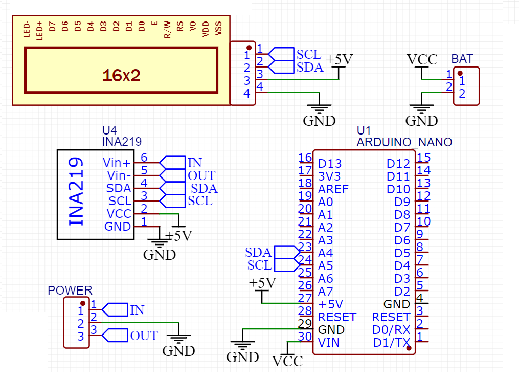
Circuit diagram:
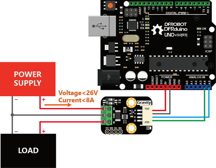
Wattmeter sensor and the LCD both are compatible with Arduino I2C bus. With different address you can plug up to 127 devices to this but here we are using only a sensor and LCD. VCC is connected to 5volts, GND is common to all, SCL to A5 and SDA to A4 of Arduino. The microcontroller is directly powered by USB. A PCB prototype shield is given below where you can directly plug the electronics and we are ready to go.
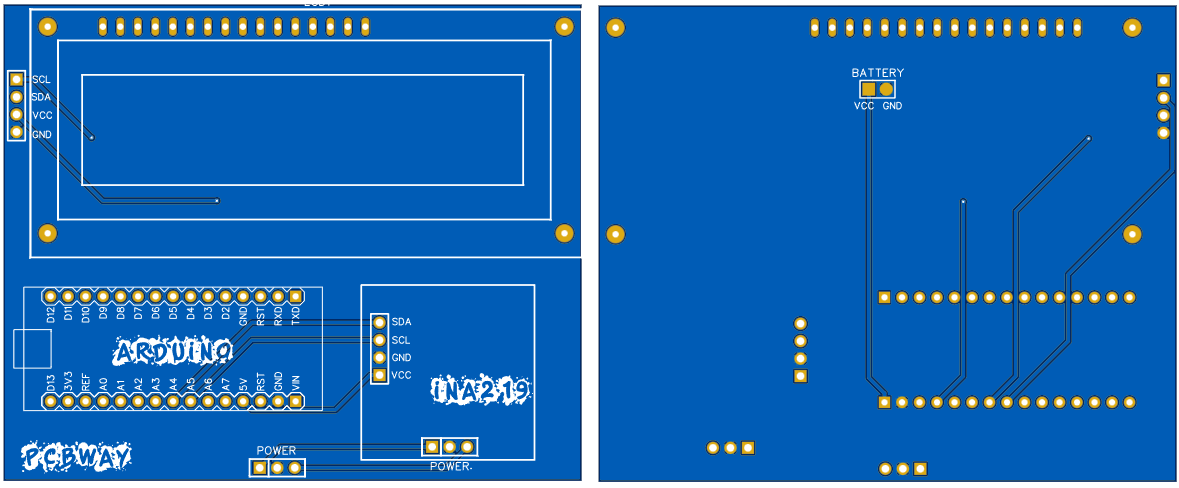
Gerber files and PCB specs:
In this PCB shield Arduino, LCD and wattmeter sensor can be plugged directly. Arduino voltage regulator is enough to get a linear 5v for the external circuitry. Battery connection are given at the bottom layer, so it can be directly powered using +12v or +9v battery. Download all the required schematics and PCB files from here.
Arduino Code:
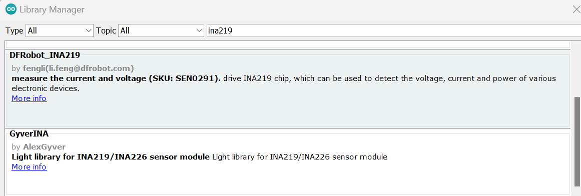
Download LiquidCrystal_I2C and DFrobot_INA219 library from the manage library section under the tool menu. Install the latest version of these libraries and check the example codes given under them through Arduino IDE.
#include <Wire.h>
#include "DFRobot_INA219.h"
#include <LiquidCrystal_I2C.h>
/**
   Change the position of slide switches according to the used address
 * @n INA219_I2C_ADDRESS1  0x40   A0 = 0  A1 = 0
 * @n INA219_I2C_ADDRESS2  0x41   A0 = 1  A1 = 0
 * @n INA219_I2C_ADDRESS3  0x44   A0 = 0  A1 = 1
 * @n INA219_I2C_ADDRESS4  0x45   A0 = 1  A1 = 1
 * These Four Address are available "check your using 12C scanner from Wire lib examples".
  */

DFRobot_INA219_IIC     ina219(&Wire, INA219_I2C_ADDRESS4);
LiquidCrystal_I2C lcd(0x27,16,2);  // set the LCD address to 0x27 for a 16 chars and 2 line display

// Revise the following two paramters according to actual reading of the INA219 and the multimeter
// for linearly calibration

float ina219Reading_mA = 1000;
float extMeterReading_mA = 1000;

void setup(void)
{
    lcd.init();   // initialize the lcd
    lcd.init();
    lcd.backlight();
    lcd.setCursor(3,0);
    lcd.print("Precision");
    lcd.setCursor(3,1);
    lcd.print("Wattmeter");
    delay(500);
    lcd.clear();

    Serial.begin(115200);
    //Open the serial port
    while(!Serial);

    Serial.println();
    //Initialize the sensor
    while(ina219.begin() != true) {
        Serial.println("INA219 begin failed");
        delay(2000);
    }
    //Linear calibration
    ina219.linearCalibrate(/*The measured current before calibration*/ina219Reading_mA, /*The current measured by other current testers*/extMeterReading_mA);
    Serial.println();
}

void loop(void)
{
    Serial.print("BusVoltage:   ");
    lcd.setCursor(0,0); // Voltage
    lcd.print("V:");
    Serial.print(ina219.getBusVoltage_V(), 2);
    lcd.setCursor(2,0); // Voltage
    lcd.print(ina219.getBusVoltage_V(), 2);
    Serial.println("V");

    Serial.print("ShuntVoltage: ");
    Serial.print(ina219.getShuntVoltage_mV(), 3);
    Serial.println("mV");

    Serial.print("I:");
    lcd.setCursor(8,0); // Current
    lcd.print("I:");
    Serial.print(ina219.getCurrent_mA(), 1);
    lcd.setCursor(10,0); // Voltage
    lcd.print(ina219.getCurrent_mA(), 1);
    Serial.println("mA");

    Serial.print("Power:        ");
    lcd.setCursor(2,1); // Power
    lcd.print("Power:");
    Serial.print(ina219.getPower_mW(), 1);
    Serial.println("mW");
    Serial.println("");
    lcd.setCursor(8,1); // Power
    lcd.print(ina219.getPower_mW(),1);
    delay(1000);
}
Calibration:
If you don't have a regulated power supply nor a DC electronic load on the hand, follow the steps below to calibrate the current measurement:
Connect the Arduino UNO, multimeter (switch to amperemeter) and load (gas sensor, motor or LCD screen etc. ) as shown below. It is recommended that the load power consumption should no less than 100mA.
Upload the following sample code to Arduino UNO.
Modify the value of the variable "float ina219Reading_mA = 1000;" according to the readings of the serial port print "Current" and "float extMeterReading_mA = 1000;" according to the current readings of the multimeter.
Upload the sample code to Arduino UNO again and Calibration finished.
The calibrated parameters "ina219Reading_mA" and "extMeterReading_mA" can now be used in this specific wattmeter module without recalibration for each measurement.
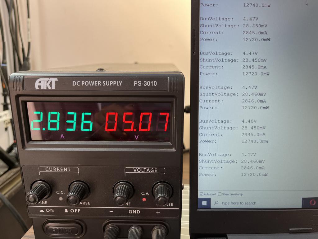
Working and Demonstration:
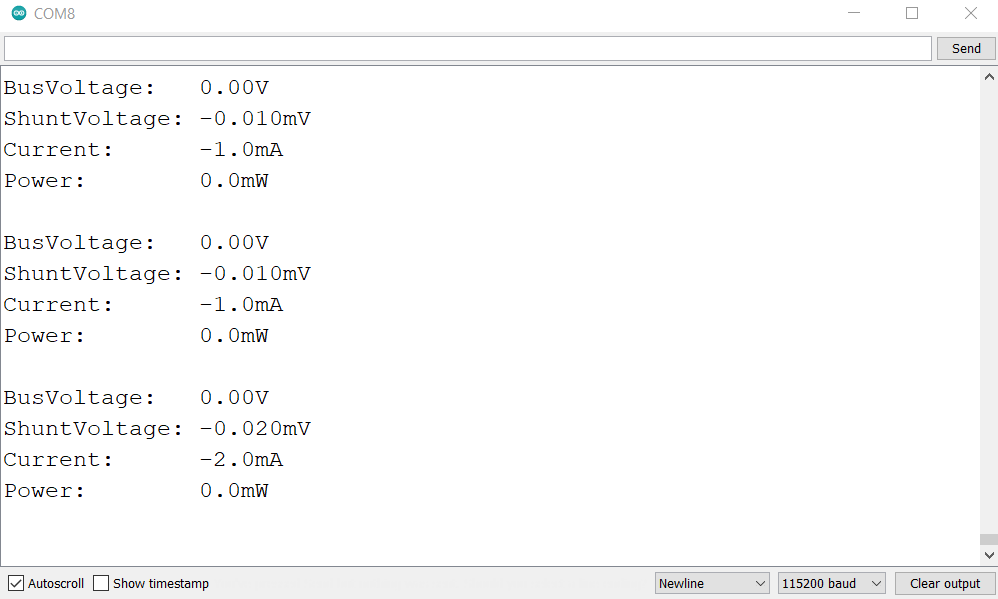
I supplied all the circuitry with 5v USB power and then made some test, as mentioned in the specification this wattmeter module is able to detect even very small amount of current that’s why I tried to go with a small LED and you can see all the details on screen. Code may be changed/ modified if you want to use small OLED display.
The article was first published in Hackaday on 28th October, 2022
cr: https://hackaday.io/project/188018-another-precision-wattmeter-module-ina219
Author: Lithium ION


 DFR0868DFR0706-ENSEN0501SEN0193DFR0063DFR0888-12DFR0981DFR0478DFR0658SEN0321SEN0170SEN0471DFR0058FIT0895SEN0305ROB0128DFR0305DFR0282DFR0745FIT0502DFR0554DFR0558FIT0585DFR0181FIT0793DFR0937DFR0439DFR0759SEN0304DFR0483DFR0868DFR0706-ENSEN0501SEN0193DFR0063DFR0888-12DFR0981DFR0478DFR0658SEN0321SEN0170SEN0471DFR0058FIT0895SEN0305ROB0128DFR0305DFR0282DFR0745FIT0502DFR0554DFR0558FIT0585DFR0181FIT0793DFR0937DFR0439DFR0759SEN0304DFR04833164


