
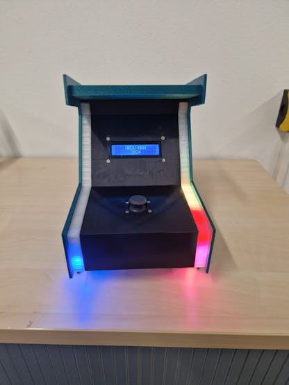
The Ardu-Man console is a small arcade machine where you can play a simplified version of Pac-Man with sound and light effects.

Software apps and online services
- Autodesk Fusion: For designing the 3D model of the case
- Autodesk EAGLE: To create the file for the board milling machine
- Meshmixer: To edit the audio files for the Pacman sounds
- Arduino IDE: To edit and write the code
Hand tools and fabrication machines
Soldering iron (generic)
3D Printer (generic)
Board milling machine
Mini Side Cutter, 120mm Length with 25mm Jaw Capacity
Digilent Screwdriver
Solder Wire, Lead Free
Mastech MS8217 Autorange Digital Multimeter
Digilent Mastech MS8217 Autorange Digital Multimeter
tweezer
Story
Background
We started our project after watching a video by bleepbit, featuring a cheap game console.
After exploring his website, we decided to rebuild the console:https://www.bleepbit.com/2018/10/28/the-7-poor-mans-console-arduino-project-joystick-and-lcd-display/
Beginning
We initially worked with a basic breadboard setup. Unfortunately, we encountered a few issues with the original code. The pin mode for the joystick button wasn’t correct, and the movement values for the joystick needed adjustments. After resolving these issues, the game worked smoothly.
Once this was done, we decided to design a casing for the LCD and joystick. At this point, we were using an Arduino UNO.
Expansions
After a while, we decided to expand our project. We wanted to add lights and sound effects. The sound effects were realized using a DFPlayer Mini and a 3W speaker. We used the DFRobotDFPlayerMini library for the sound, and for the LEDs, we chose regular NeoPixels with the Adafruit_NeoPixel library.
After encountering a few issues with the DFPlayer, we focused first on the LED lighting. We wanted the LEDs to display green for a completed level and red for a game over. For the rest of the game, we wanted a smooth-running light pattern using the original Pac-Man colors (blue, orange, pink, red, yellow). We used an RGB color grid to find the right colors and tested various color settings.
Once the lighting was complete, we realized that a single Arduino couldn’t handle all the required functions. As a result, we decided to connect three Arduino Nanos via the I²C bus. This allowed us to send messages from the main Arduino to the other two, which would respond accordingly.
When using the I²C connection, it is crucial to connect all grounds of the Arduinos. Additionally, when uploading code to an Arduino, the SDA, SCL, and GND connections between the Arduinos need to be disconnected to avoid faulty uploads.
We then returned to the DFPlayer Mini to address some remaining issues. The primary issue was the initialization of the DFPlayer, which failed multiple times. Adding a small delay in the setup solved the problem. We also found that the DFPlayer and the I²C connection were very sensitive to loose ground connections. On the breadboard, we had some issues with jumper wires not fitting properly. After some time, everything worked well on the breadboard, and we began designing the PCB.

PCB
For the PCB, we used a single-layer circuit board. The design was created using an older version of EAGLE. We mainly used socket strips and pin headers for the connections of external components. We needed just a few SMD resistors: two 4.7kΩ for the I²C bus pull-ups and one 1kΩ resistor for the DFPlayer Mini.
In our current design, we soldered a few wires directly onto the circuit board, which we would replace with pin headers in a future version. Additionally, the connections for the joystick and display were twisted, which is not optimal. If you do not have the equipment to create a single-layer circuit board, you could also build the entire project using a hole grid board.


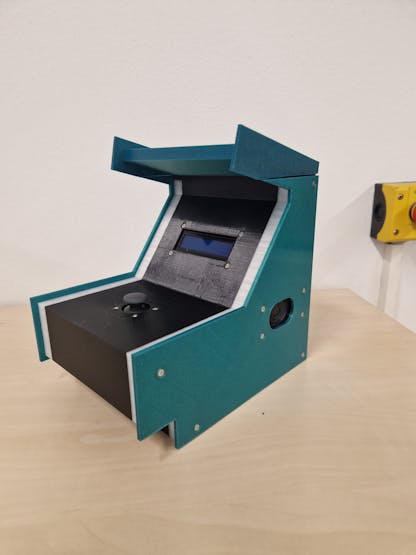
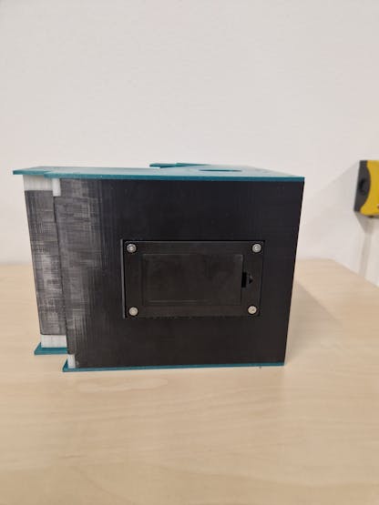
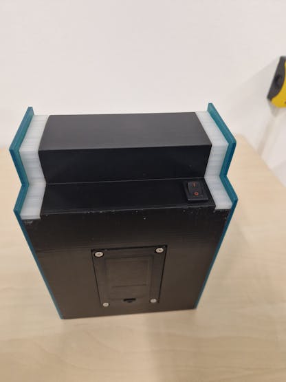
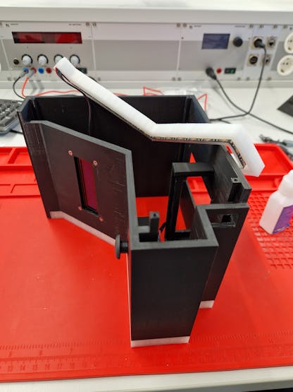
Console Design
We completely designed the console ourselves, drawing inspiration from retro arcade designs. The 3D modeling was done using the free version of Fusion 360. You are welcome to use our print files, but please note that we forgot to account for tolerances in the 3D print, so some parts may fit very tightly. Additionally, the model is designed for our exact components; if yours differ slightly, the dimensions may not match. We printed the casing with two colors of PLA and used transparent Nylon for the LED holders. The 3D printing would take about 50 hours.

Problems Encountered
Throughout the project, we encountered several issues that needed to be resolved:
- Pin 13 Issue: Due to PCB layout limitations, we had to use digital pin 13 for the joystick button. Since the button is active-low, a pull-up resistor was required. However, the LED on pin 13 interfered with the internal pull-up of the Arduino. To solve this, we had to remove the LED from the Arduino since the PCB was already completed.- Space Constraints: The joystick holders were quite large, causing space issues in the casing. To resolve this, we had to cut the pin headers on top of the Arduino, specifically the central Arduino responsible for the LEDs.- Fitting Issues: As shown in the STL files for our casing, we had to cut the object at the top to fit it onto our 3D printer (Ultimaker S3).- Loose Connections at the Display: Loose connections caused interference with the I²C communication, causing the display to show random symbols. To fix this, we recommend using high-quality jumper wires or directly soldering the wires to the PCB of the display.Custom parts and enclosures
- complete console: Sketchfab still processing.
- basic body: Sketchfab still processing.
- Led stripe left: Sketchfab still processing.
- LED stripe right: Sketchfab still processing.
- left sidepanel: Sketchfab still processing.
- right sidepanel: Sketchfab still processing.
- Roof: Sketchfab still processing.
- 0001pacman_sound.mp3
- 0002waka_waka_pacman.mp3
- 0003pacman_death_sound.mp3
- 0004pacman_new_level.mp3
- video from running light
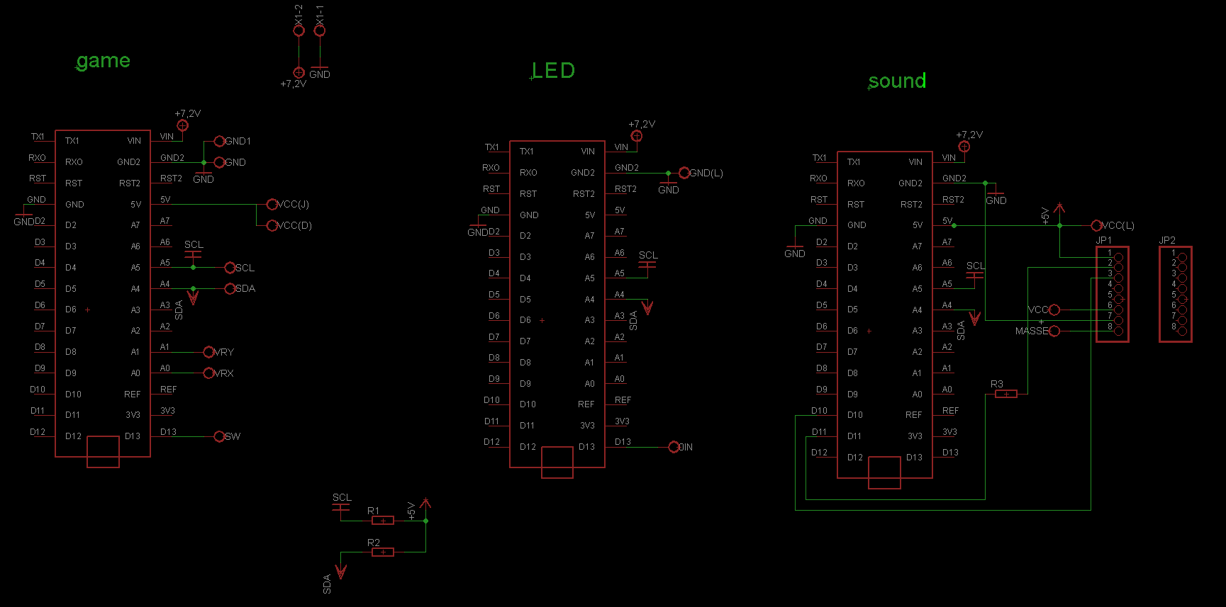
Schematics
circuit diagram
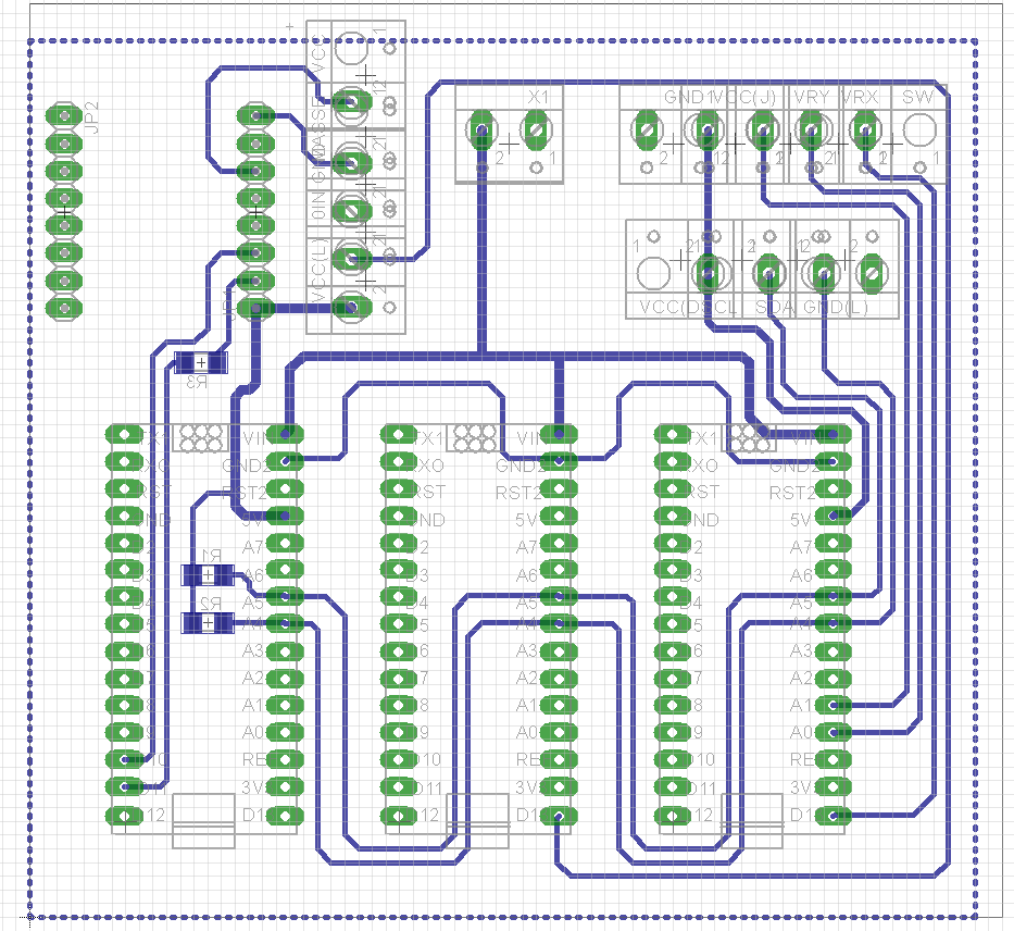
circuit board layout
Code
This article was first published on Hackster on Jan 16, 2025
cr: https://www.hackster.io/t-h-m-w/ardu-man-2024-de1657
Author: T.H,M.W


