Story
In the last LattePanda article, we just unboxed and explored the LattePanda 3 Deltas features and applications. Now are going to see the internal Arduino core of LattePanda 3 Delta then will try to integrate some sensors and communicate with them.
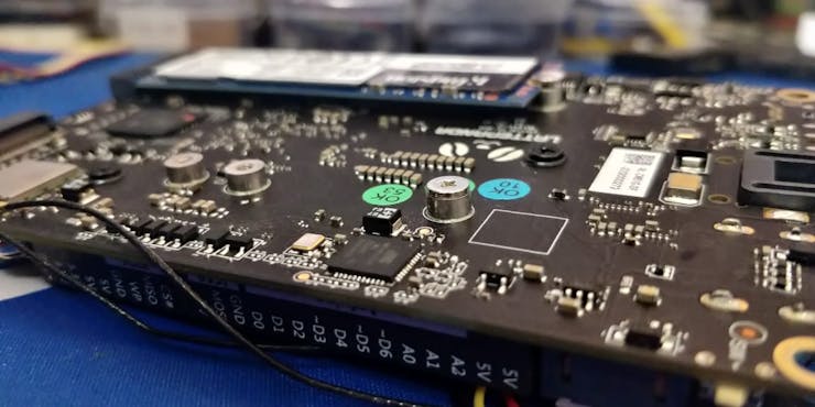
LattePanda 3 Delta Arduino Core ?:
![](https://hackster.imgix.net/uploads/attachments/1568771/image_nPSZULXt5w.png?auto=compress%2Cformat&w=740&h=555&fit=max)
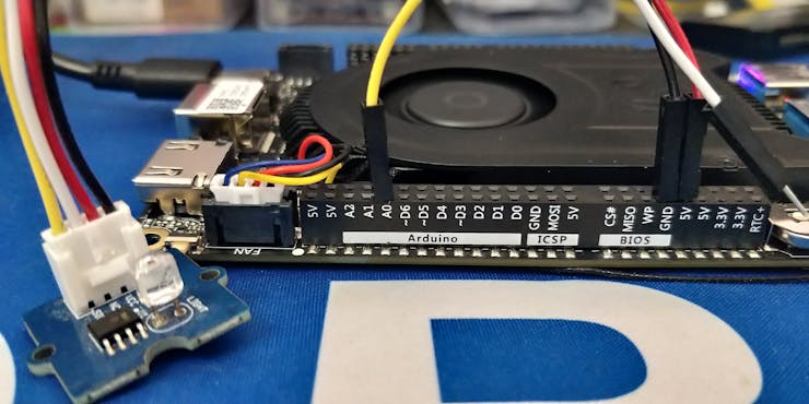
As you can see there is a separate pin header in LattePanda 3 Delta, which is compatible with Arduino. That means there is an internal Arduino controller. We can directly use that for our projects.
![](https://hackster.imgix.net/uploads/attachments/1568773/image_sy1o9DFMt4.png?auto=compress%2Cformat&w=740&h=555&fit=max)
The Arduino Leonardo ATMEGA32U4 is the internal Arduino core in LatteOand 3 Delta.
![](https://hackster.imgix.net/uploads/attachments/1568775/image_ll6S5vweKm.png?auto=compress%2Cformat&w=740&h=555&fit=max)
Arduino IDE ?️:
First let's look into the Arduino IDE setup in LattePanda 3 Delta, don't worry about the IDE & Driver installation. Since the Arduino IDE is preinstalled in the LattePanda 3 Delta board.
![](https://hackster.imgix.net/uploads/attachments/1568778/image_3FB6bREtUd.png?auto=compress%2Cformat&w=740&h=555&fit=max)
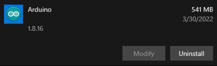
Also, the appropriate drivers are installed.
![](https://hackster.imgix.net/uploads/attachments/1568777/image_ArbtbzoeNs.png?auto=compress%2Cformat&w=740&h=555&fit=max)
Now all the software setups are already done. So, we can directly move on to the hardware connections.
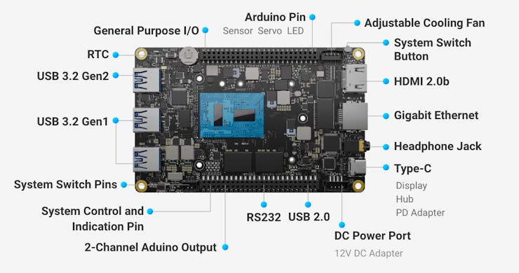
LattePanda 3 Delta Pinouts ⚙️:
Here is the overall pinout diagram of the LP3 Delta's IO.
![](https://hackster.imgix.net/uploads/attachments/1568779/image_7I3kTBuY2m.png?auto=compress%2Cformat&w=740&h=555&fit=max)
![](https://hackster.imgix.net/uploads/attachments/1568780/image_yekJWdJyXi.png?auto=compress%2Cformat&w=740&h=555&fit=max)
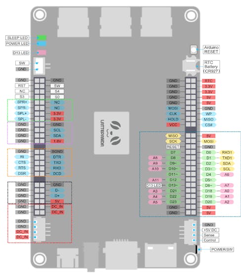
In this, you can see the D13 pin is directly connected to the internal programmable LED.
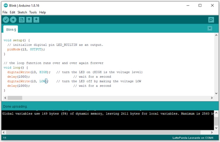
Let's Blink the LED ?:
Launch the Arduino IDE in the LattePanda 3 Delta and open up the blink sketch
Note: Change the pin to 13.
![](https://hackster.imgix.net/uploads/attachments/1568792/image_OdJIcWp0LT.png?auto=compress%2Cformat&w=740&h=555&fit=max)
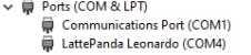
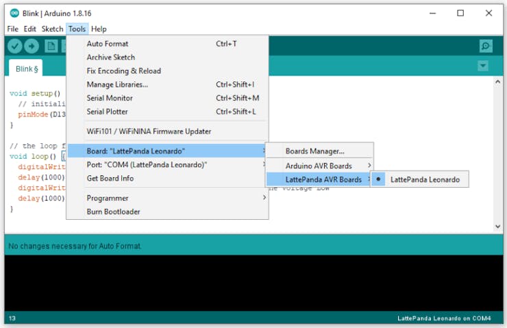
Next, choose the board type as LattePanda Leonardo.
![](https://hackster.imgix.net/uploads/attachments/1568783/image_Rz5fEdnHej.png?auto=compress%2Cformat&w=740&h=555&fit=max)
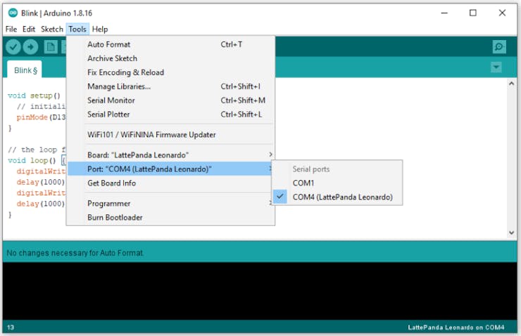
Then choose the correct port number.
![](https://hackster.imgix.net/uploads/attachments/1568784/image_0xit1xEHIn.png?auto=compress%2Cformat&w=740&h=555&fit=max)
That's all, upload the code to the board.
![](https://hackster.imgix.net/uploads/attachments/1568785/image_AfYAyr39fF.png?auto=compress%2Cformat&w=740&h=555&fit=max)
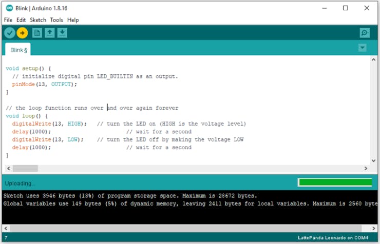
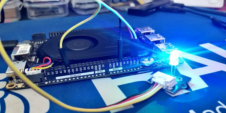
You can see the red LED is blinking. So, we can control this led via Arduino IDE.
Next, I have connected the grove led module to the LP3 pin 13.
![](https://hackster.imgix.net/uploads/attachments/1568793/img_20230312_113044_GdjA6BsqPo.jpg?auto=compress%2Cformat&w=740&h=555&fit=max)
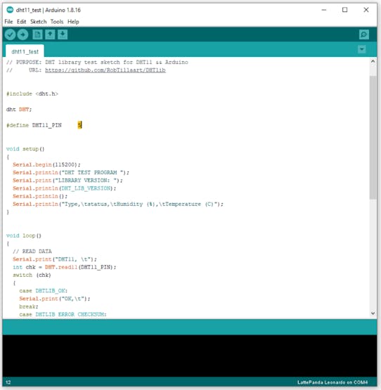
DHT11 with LattePanda 3 Delta ?️:
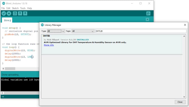
To use the DHT11 sensor, first, we need the DHT11 library. Go to the library manager and search for DHTLIB and install the library.
![](https://hackster.imgix.net/uploads/attachments/1568795/image_rLnx4rB23a.png?auto=compress%2Cformat&w=740&h=555&fit=max)
Then select the DHT11 Sensor test code in the examples.
![](https://hackster.imgix.net/uploads/attachments/1568796/image_n2L0LWIwcv.png?auto=compress%2Cformat&w=740&h=555&fit=max)
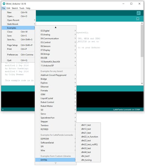
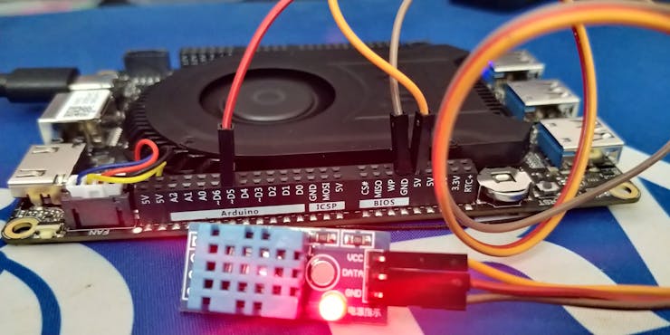
Note in this example code they are using Digital Pin 5. So, we have to connect the DHT11 with pin 5 of the LP3 Arduino.
![](https://hackster.imgix.net/uploads/attachments/1568797/image_U4xIOwrnGz.png?auto=compress%2Cformat&w=740&h=555&fit=max)
Upload the code and open the serial monitor.
Note: Set baud rate as 115200
![](https://hackster.imgix.net/uploads/attachments/1568798/image_4OwRE1sgUi.png?auto=compress%2Cformat&w=740&h=555&fit=max)
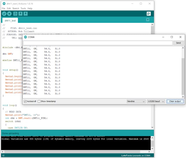
It will show you the Sensor status, Humidity level, and Temperature readings.
![](https://hackster.imgix.net/uploads/attachments/1568800/img_20230312_115013_J5nTFKWwDv.jpg?auto=compress%2Cformat&w=740&h=555&fit=max)
Light Sensor with LattePanda 3 Delta :
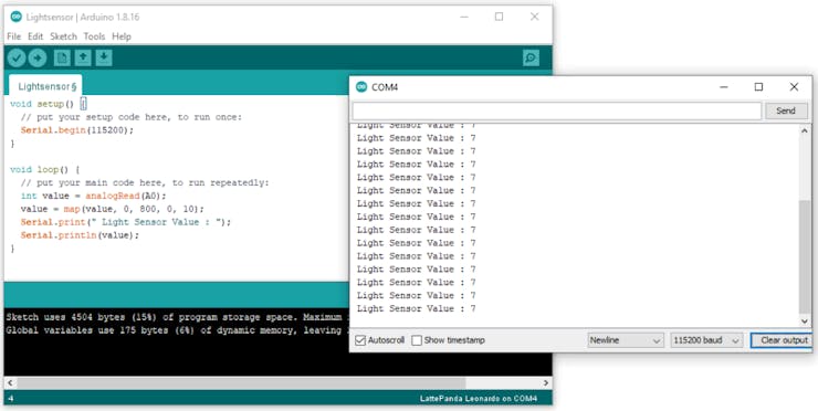
Next, let's try out some simple automation projects. In this, we are going to build LDR control LEDs. First, connect the LDR sensor pin to the analog pin of Lattepanda 3 Delta.
Note: In this I'm using Analog pin0.
![](https://hackster.imgix.net/uploads/attachments/1568802/image_GQBrh2dgEq.png?auto=compress%2Cformat&w=740&h=555&fit=max)
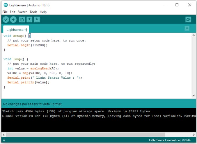
I have added the mapping function to round off the values into 10.
![](https://hackster.imgix.net/uploads/attachments/1568803/img_20230312_121047_LgyvVvsTMc.jpg?auto=compress%2Cformat&w=740&h=555&fit=max)
Upload the code and look at the serial monitor results.
![](https://hackster.imgix.net/uploads/attachments/1568804/image_nadC0OHbtW.png?auto=compress%2Cformat&w=740&h=555&fit=max)
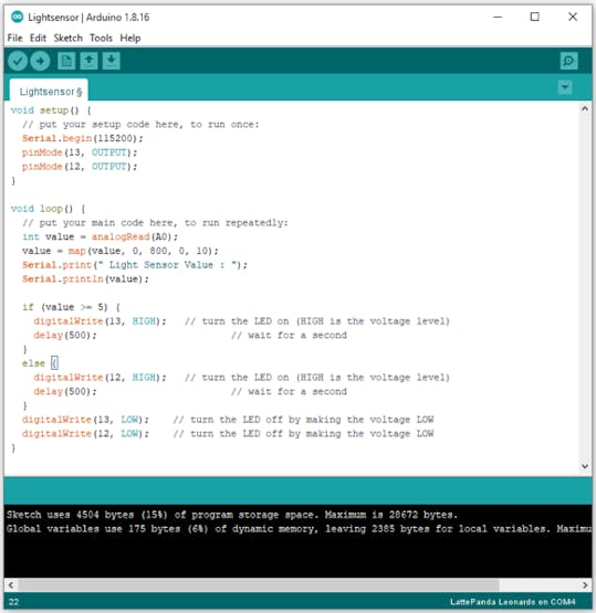
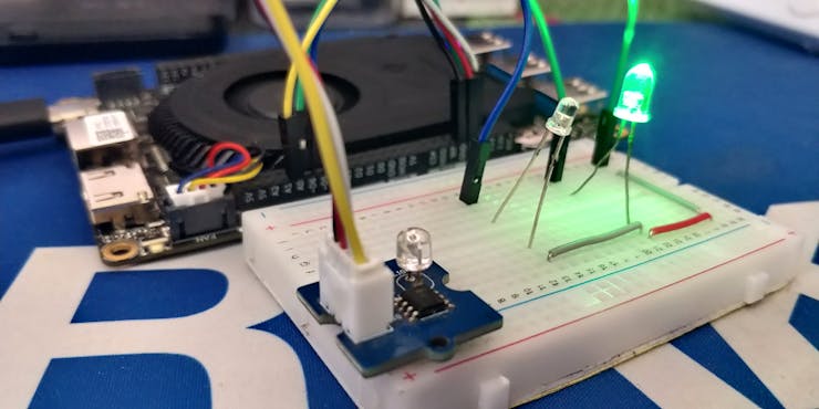
Next, we are going to add some led control. If the light value is below 5 it will turn off the green light and turn on the white led. Here is the complete code.
![](https://hackster.imgix.net/uploads/attachments/1568805/image_XJ0KPKindm.png?auto=compress%2Cformat&w=740&h=555&fit=max)
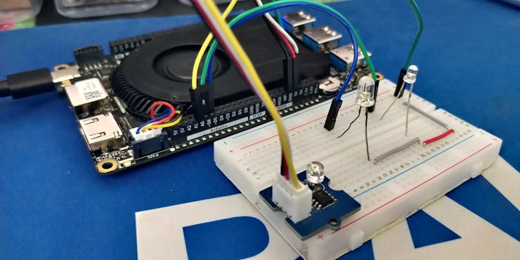
Here is the hardware connection.
![](https://hackster.imgix.net/uploads/attachments/1568806/img_20230312_121921_KZWgqqGkab.jpg?auto=compress%2Cformat&w=740&h=555&fit=max)
Wrap-Up:
![](https://hackster.imgix.net/uploads/attachments/1568810/img_20230312_124614_rwOOPp6WlX.jpg?auto=compress%2Cformat&w=740&h=555&fit=max)
In this article, we see how to access the Arduino core of the LattePanda3 Delta and some basic guides, Hope it helps. Will come up with another project. Thank you.
![licensBg](/images/license_bg.png)