
I decided to create a watch that is both digital and has a vintage look. So I created digiPclock.
Things used in this project
Hardware components
DigiPclock - a Digital Pocket Clock
Hello everyone!
In this smart watch era, where people are forgetting about old watches, I decided to create a watch that is both digital and has a vintage look. So I created digiPclock.
Buy this digiPclock from Tindie Store.
By the way, subscribe to my YouTube channel for more projects like this. I also update my upcoming projects on Instagram.
What is digiPclock
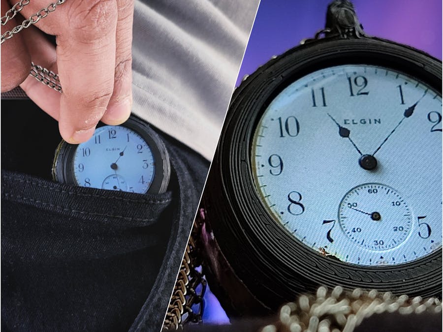
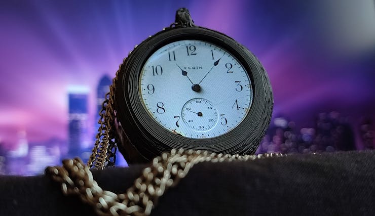
digiPclock is a digital pocket clock. A pocket watch is a watch that is made to be carried in a pocket, as opposed to a wristwatch, which is strapped to the wrist. So I added a digital screen to this pocket watch, so the face looks like an old analogue clock.

How digiPclock Works
digiPclock has an ESP32, which is the heart of this project. ESP32 has inbuilt RTC so no need to connect external RTC for Correct time information. It shows an analogue clock on the GC9A01 LCD display. The time can be set by the portal. The whole system runs on batteries, so battery saving is also important. I added sleep functionality to reduce battery consumption. There is a type-C port that is used to charge the device. Good thing about it is, it does not require internet.
DFRobot
This project is sponsored by DFRobot, and they have sent me the DFRobot Beetle ESP32-C3 and other stuff to help me in this project. Check out the link for more products.
Link to DFRobot :- https://www.dfrobot.com/?tracking=6364c322dda19
Traditional Pocket Clock
They were the most common type of watch from their development in the 16th century until wrist watches became popular after World War I, during which a transitional design, trench watches, were used by the m ilitary. Pocket watches generally have an attached chain to allow them to be secured to a waistcoat, lapel, or belt loop and to prevent them from being dropped. Watches were also mounted on a short leather strap or fob when a long chain would have been cumbersome or likely to catch on things. This fob could also provide a protective flap over their face and crystal. Women's watches were normally of this form, with a watch fob that was more decorative than protective. Chains were frequently decorated with a silver or enamel pendant, often carrying the arms of some club or society, which by association also became known as a fob.
Supplies
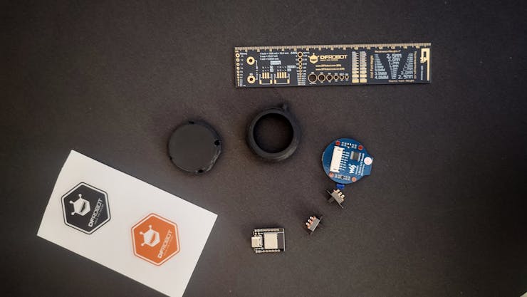
DFRobot Beetle ESP32 – C3GC9A01 Round DisplaySlide SwitchSquare head tactile switch with capBattery 600mAhSome Wires3D printM2x3 mm Brass insertsM2x8 mm BoltsZero PCBBC857 Transistor10 Ohm resistor
DFRobot Beetle ESP32 – C3
Beetle ESP32-C3, mainly intended for IoT applications, is a controller based on the ESP32-C3 RISC-V 32-bit single-core processor. It has inbuilt charging IC which is TP4057, so it can charge battery with it's type-C port.
GC9A01 Round Display
The driver used in this LCD is GC9A01, with a resolution of 240×240 RGB dots and 129600 bytes of RAM inside. This LCD supports a 12-bits/16-bits/18-bits data bus by MCU interface, which are RGB444, RGB565, RGB666.
3D print
3D prints were made in Tinkercad and printed on a 3D printer in black ABS. The design is very handy and small, made in such a way that it looks like an actual pocket clock.
Slide Switch
here I am using single pole double throw slide switch, there are two switches used in project, both Switches has there specific purpose.
Battery 600mAh
I am using 600mAh Li-Po battery here, A lithium polymer battery, or more correctly, a lithium-ion polymer battery, is a rechargeable battery of lithium-ion technology that uses a polymer electrolyte instead of a liquid electrolyte. High-conductivity semisolid (gel) polymers form this electrolyte. These batteries provide higher specific energy than other lithium battery types and are used in applications where weight is a critical feature, such as mobile devices, radio-controlled aircraft, and some electric vehicles.
How to Use DigiPclock
digiPclock is digital pocket clock has 3 features, all three features name are given below.
Time Setting ModeTime Display ModeSleep Mode
Time Setting Mode
In time-setting mode, the time can be configured by a portal (web page). To enter Time Setting Mode, press the mode button and slide the power switch to turn on the device. The instruction to set up time will be displayed in the display.
After entering in time setting mode, turn on wifi in mobile and search for digiPclock wifi. Connect wifi to the digiPclock, as soon as the wifi is connected the mobile will get notification named sign in. Opening the notification will open a web page.
web page has a setup button and a exit button, click on setup button then there will be drop down menu to setup hour and minutes. select hour and minute as your time and click on save, as soon as the setting saved the hotspot from digiPclock will be off and the watch will show time.
Sleep mode
if everything is right, the display will show going to sleep and the screen will turn black. This feature was added to save battery life because, in sleep mode, the ESP draws less current, which can extend the run time of the device.
Time Display Mode
In Time Display Mode, the watch will show an analogue clock on the display; this mode can be turned on by pressing the button on Right. It wakes the ESP32 from sleep and shows the time on the display. Release the button to go into sleep mode.
Charging
There is a Type-C port below the device, so it can be charged by inserting a regular Type-C mobile charger. It takes almost 1 hour and 30 minutes to fully charge. It can run up to 4 days.
3D in Tinkercad
3D Enclosure for This project is made in TinkerCad.
Tinkercad is very easy to use online website by is atodesk. This is completely online, so there is no need to install anything, and there is no system configuration or OS dependency. It can run anywhere in the browser.
I have used different shapes and sizes to make the 3D, and the smoothing feature can reduce sharp edges and turn them into nice curves.
The STL file can be found on tinker cad from this link.
The printing settings, which I used are given below.
Material: ABS - BlackNozal: 0.2 mmInfill: 40%
Install the Library
Make sure Arduino IDE is installed in your PC and basics are clear about the Arduino.
Before uploading the code, the Arduino IDE should have a supported library. The TFT_espi is the best library for displays; it can run almost all types of displays, even e-paper displays.
I am a fan of this library; check out my old project based on it (the uncanny eye pendant).
To download this library go in sketch >> include library >> manage libraries, here search for TFT_espi by bodmer.
Also need to download WiFiManager by tzapu and ESP32Time by fbiego.
After downloading the library there need to do some changes in TFT library to get library work. For this, go to My PC.
My PC >> Documents >> Arduino >> Library >> TFT_espi
Here there is User_setup File Open the file comment the driver in 45 line, and uncomment driver in 65 line, which is "#define GC9A01_DRIVER".
Now comment out "pin" defined in lines 169, 170, and 171 and add the pin definition given below.
#define TFT_MOSI 6
#define TFT_SCLK 4
#define TFT_CS 7
#define TFT_DC 1
#define TFT_RST 5
Upload the Code
Download the Code from my github page. Extract the folder and open digiPclock.ion file in arduino IDE. make sure All ESP boards package are installed in the arduino IDE. Connect the DFRobot Beetle ESP32 – C3. Open Toole >> Board ESP32 >> ESP32C3 Dev Module. Select Port where the Board is connected. (if you not find the port watch this video)Now Click on Upload Button.
The compilation of code will take some time; it depends on system configurations. After uploading the code, the circuit can be connected to test the code.
https://github.com/vishalsoniindia/digiPclock
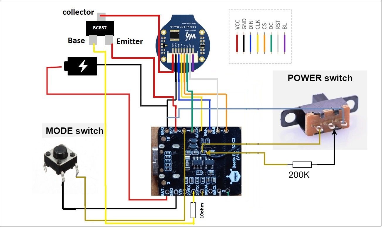
Circuit Connections
After uploading the code to ESP32C3, ESP is now ready to connect with the circuit. I have divided the circuit into three parts.
I have removed all screw holders and connectors from the display to save some space.
Display ConnectionSwitch ConnectionTransistor ConnectionsBattery Connection
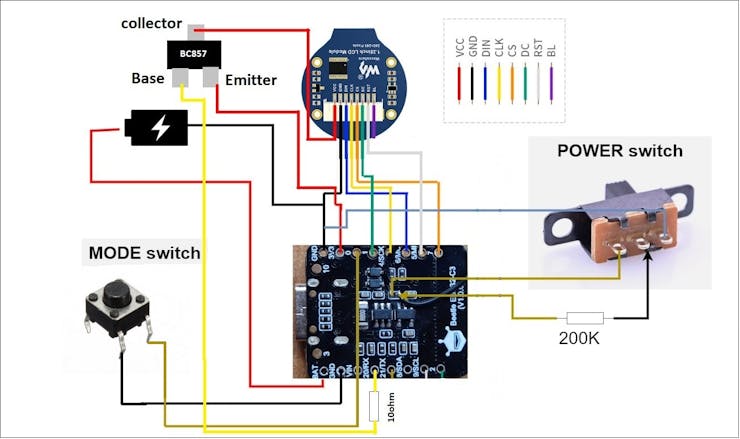
Display Connections
As given in the diagram, there are 8 pins that will be connected to the ESP32C3.
ESP32C3 pins GC9A01 Display Pinout
3V3 ------------------> VCC
GND ------------------> GND
6 ------------------> DIN
4 ------------------> CLK
7 ------------------> CS
1 ------------------> DC
5 ------------------> RST
Switch connections
There are two switches. One is Mode Switch (tactile switch) and other one is Power Switch (slide switch).
Mode switch:- Connect One leg to GND and other to 0 number pi Power Switch:- The DFRobot Beetle ESP32 – C3 not has on/off switch, but this is open source so it can be easily found out where to place the switch. I will add the switch to the 3.3V LDO right after charging the IC. so charging IC works even device is shut off. The middle leg will be connected to the enable pin of the LDO through a 200K resistor. One of the side pins will be connected to diodes as shown in the circuit, and the other pin will be connected to GND.
Transistor Connection
Connect emitter to 3.3v, collector to VCC of battery and base to 20 number pin via 10 ohm resistor.
Battery Connection
The positive terminal of the battery is connected to the BAT of the ESP32C3, and the negative to GND.
Testing the Watch
Ok After All the connection Watch is Ready to test.
There are three modes to test here.
Time Setting ModeTime Display ModeSleep Mode
Time Setting Mode
In time-setting mode, the time can be configured by a portal (web page). To enter Time Setting Mode, press the mode button and slide the power switch to turn on the device. The instruction to set up time will be displayed in the display.
After entering in time setting mode, turn on wifi in mobile and search for digiPclock wifi. Connect wifi to the digiPclock, as soon as the wifi is connected the mobile will get notification named sign in. Opening the notification will open a web page.
web page has a setup button and a exit button, click on setup button then there will be drop down menu to setup hour and minutes. select hour and minute as your time and click on save, as soon as the setting saved the hotspot from digiPclock will be off and the watch will show time.
Sleep mode
if everything is right, the display will show going to sleep and the screen will turn black. This feature was added to save battery life because, in sleep mode, the ESP draws less current, which can extend the run time of the device.
Time Display Mode
In Time Display Mode, the watch will show an analogue clock on the display; this mode can be turned on by pressing the button on Right. It wakes the ESP32 from sleep and shows the time on the display. Release the button to go into sleep mode.
Charging
There is a Type-C port below the device, so it can be charged by inserting a regular Type-C mobile charger. It takes almost 1 hour and 30 minutes to fully charge. It can run up to 4 days.
Current Consumption
I have connected multimeter in between battery and ESP32C3 bat terminal, the current at the time of Time Display mode is 110mA and in sleep mode is 5.9mA, So the battery can run up to 4 days if it is in sleep Mode.
The current consumption can be reduced by some custom modifications to the circuit and components, which I think are for the next version.
Closing Things in 3D Enclosure
My round display has some extra PCB edges, so I will remove them by sending it with sending paper.
Insert brass inserts with the help of a soldering iron.
Carefully insert the display battery and ESP32, place switches on the side, and close it carefully.
Done
Whooooo!!!!!!!
The Project Is completed Go between your friend and family and show up this watch.
Custom parts and enclosures
Schematics
DigiPclock
Code
The article was first published in hackster, April 16, 2023
cr: https://www.hackster.io/Vishalsoniindia/digipclock-a-digital-pocket-clock-01dc13
author: Vishalsoniindia


