
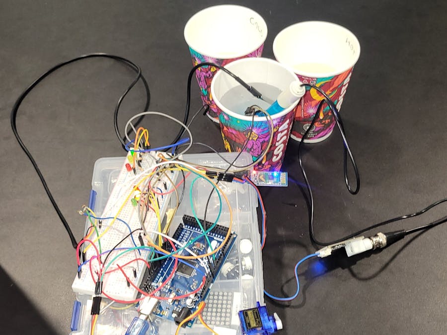
A microcontroller project to be used in wastewater treatment plant for uses like irrigation and purification
Things used in this project
Hardware components
Software apps and online services
ArduiTooth
Serial Bluetooth Terminal
Story
Water level sensor ( Abdullah) :
The water level sensor was used to send alerts that indicates if the water level is high, medium, or low, in response to that the servo motor receives this signal as an input to do a programmed action either by opening or closing the valve.
Servo motor (Aref) :
Temperature Sensor (Bithal ):
PH Sensor (Joy): using the water sensor we measure the PH level of the water to insure it is within safe operating levels for irrigation and to insure the good bacteria in the solution do not die from the acidity of the base of the water.
Display Interface( Ivy): As shown in the project, the system involves a lot of LEDs. To properly understand what is going on, a Bluetooth module was incorporated. This allows anyone with a Bluetooth-enabled device to connect to the system and see what is happening with water levels, PH, and temperature in real time.
Schematics
Water level Sensor ( tinkercad Circuit )
Ultrasonic sensor was used a replacement since there's not level indicator sensors in tinker cad library
_KxGPXEtwCm.png)
Water level sensor ( Schematic View )
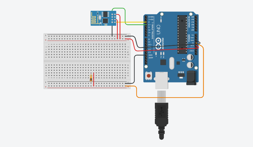
Bluetooth Connection
To create a wireless connection between the board and Bluetooth-enabled devices.
Code
PH sensor
Arduino
#define SensorPin A2            //pH meter Analog output to Arduino Analog Input 0
#define Offset 15.76      //deviation compensate
#define LED 13
#define samplingInterval 20
#define printInterval 800
#define ArrayLenth  40    //times of collection
#define uart  Serial
int pHArray[ArrayLenth];   //Store the average value of the sensor feedback
int pHArrayIndex = 0;
void setup(void)
{
  pinMode(LED, OUTPUT);
  uart.begin(9600);
  uart.println("pH meter experiment!");    //Test the uart monitor
}
void loop(void)
{
  static unsigned long samplingTime = millis();
  static unsigned long printTime = millis();
  static float pHValue, voltage;
  if (millis() - samplingTime > samplingInterval)
  {
    pHArray[pHArrayIndex++] = analogRead(SensorPin);
    if (pHArrayIndex == ArrayLenth)pHArrayIndex = 0;
    voltage = avergearray(pHArray, ArrayLenth) * 5.0 / 1024;
    pHValue = -5.882 * voltage + Offset;
    samplingTime = millis();
  }
  if (millis() - printTime > printInterval)  //Every 800 milliseconds, print a numerical, convert the state of the LED indicator
  {
    uart.print("Voltage:");
    uart.print(voltage, 2);
    uart.print("    pH value: ");
    uart.println(pHValue, 2);
    digitalWrite(LED, digitalRead(LED) ^ 1);
    printTime = millis();
  }
}
double avergearray(int* arr, int number) {
  int i;
  int max, min;
  double avg;
  long amount = 0;
  if (number <= 0) {
    uart.println("Error number for the array to avraging!/n");
    return 0;
  }
  if (number < 5) { //less than 5, calculated directly statistics
    for (i = 0; i < number; i++) {
      amount += arr[i];
    }
    avg = amount / number;
    return avg;
  } else {
    if (arr[0] < arr[1]) {
      min = arr[0]; max = arr[1];
    }
    else {
      min = arr[1]; max = arr[0];
    }
    for (i = 2; i < number; i++) {
      if (arr[i] < min) {
        amount += min;      //arr<min
        min = arr[i];
      } else {
        if (arr[i] > max) {
          amount += max;  //arr>max
          max = arr[i];
        } else {
          amount += arr[i]; //min<=arr<=max
        }
      }//if
    }//for
    avg = (double)amount / (number - 2);
  }//if
  return avg;
}
Bluetooth module
Arduino
The component is used to enable wireless communication between the Arduino board and any Bluetooth-enabled device. It operates on the Bluetooth 2.0 specification and supports both the Bluetooth Serial Port Profile (SPP) and the Bluetooth Master-Slave configuration. It enables the establishment of a reliable and convenient wireless connection between devices.
#include <SoftwareSerial.h>

SoftwareSerial mySerial(10, 11); // RX, TX

char w;

void setup() {
  Serial.begin(9600);
  mySerial.begin(9600);
  delay(1000); //wait to start the device properly
}

void loop() {
  if (mySerial.available()) {
    w = mySerial.read();
    Serial.println(w);  //PC
    delay(10);
    //commands with Serial.println(); show on pc serial monitor
  }

  if (Serial.available()) {
    w = Serial.read();
    mySerial.println(w); //Phone
    delay(10);
    //commands with mySerial.println(); show on the device app
  }

//shown on pc
Serial.println("This is a test run");
Serial.println("Congratulations! Device Connected!");
Serial.println();

//shown on device app
mySerial.println("This is a test run");
mySerial.println("Congratulations! Device Connected!");
mySerial.println();

delay(2000);
}
The article was first published in hackster, May 31, 2023
cr: https://www.hackster.io/world-microcontrollers/sewage-treatment-plant-d097b0
author: Team World microControllers: Abdullah Alsoufi Ali Alsoufi, Ivy Nabirye Wayero Mungati, AREF MOHAMMED ALWAN ALI, joy massouh


