
We have developed an embedded monitoring system that uses various low-power connected sensors.
Things used in this project
Hardware components
Software apps and online services
The Things Network [https://www.hackster.io/the-things-network/products/the-things-network?ref=project-6a9fb1]
Hand tools and fabrication machines
Plier, Cutting
Solder Wire, Lead Free
Breadboard, 270 Pin
Wire Stripper & Cutter, 18-10 AWG / 0.75-4mm² Capacity Wires
Soldering iron (generic)
Tape, Electrical
Story
Introduction
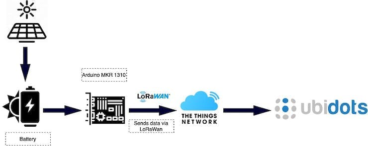
For our fourth year at Polytech Sorbonne, we have developed an embedded monitoring system that measures various low-power connected sensors. We used various sensors that transmitted data to the cloud via the LoraWAN antenna (The Things Network).
Our issue addresses the potential transmission of viruses in public spaces and the importance of refreshing the air in these spaces to limit the spread of the virus. To achieve this, it is suggested to measure the level of CO2 in closed spaces as it is correlated with the presence of people and can indicate when it is time to ventilate.
The project aims to develop a connected system equipped with sensors to measure several parameters such as the presence of people in the room, the noise level, temperature, humidity, and CO2 level. These data will then be transmitted to a server using a long-range and low-power consumption technology. The alert thresholds can be calibrated, and the system parameters can be adjusted through a web application.
The measured data will be accessible in graphical form via a web interface on a computer. The system will also send alerts when abnormal behavior is detected. This project will, therefore, enable real-time monitoring of the comfort level of the rooms and ensure health safety in public spaces.
General Schematic
USAGE SCENARIO
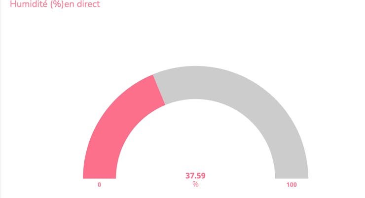
The administrator accesses the Ubidots dashboard to view all sensor data. In case of a spike in CO2 concentration in a room equipped with the monitoring system, the administrator is alerted via the website.
On this dashboard, the administrator can remotely read the following data: temperature, CO2 level, humidity level, pressure sensor, etc.
This dashboard is updated every 10 minutes, which is a relatively long time, but it allows the system to limit its power consumption and thus make it self-sustainable through the use of solar panels.
Red LED flash during 7 seconds when the limit of 1000 PPM is exceeded.
Summary of the functions to be satisfied and our response
Measuring data and sending it
Using 4 sensors:
T° et d'humidité DHT11
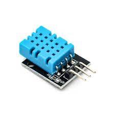
The DHT11 is a capacitive humidity sensor and a thermistor used to measure ambient air and generate a digital signal on the data pin. It is fairly easy to use and inexpensive. The only real drawback of this sensor is that new data can only be obtained once every 2 seconds.
Power Supply: 3 to 5 V
Connectors: 4 pins
Dimensions: 15.5mm x 12mm x 5.5mm
Air quality sensor CCS811 SEN0339
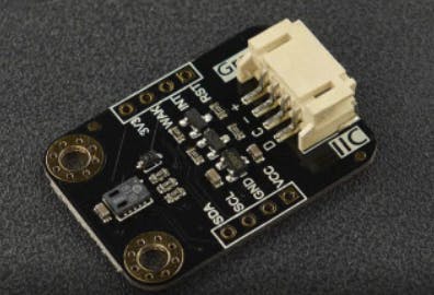
The CCS 811 is a low-power CO2 sensor that integrates a metal oxide (MOX) gas sensor to detect a wide range of volatile organic compounds (VOCs) for indoor air quality monitoring.
Power Supply: 1.8 or 3.6 VDC
Connectors: 10-pin LGA
Dimensions: 2.7 x 4.0 x 1.1 mm
Atmospheric pressure BMP388 SEN0371
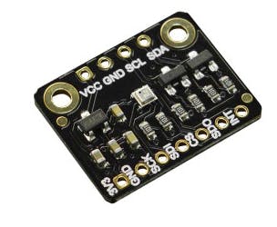
This barometric sensor is based on a BMP 388 circuit that allows for atmospheric pressure measurement. The BMP 388 circuit offers low power consumption, higher resolution, and better sampling rate compared to other sensors in the BMP series.
Power Supply: 3.3 to 5 VDC
Connectors: Male connectors
Dimensions: 18 x 11.5 mm
Fermion SEN0487 Micro MEMS Module
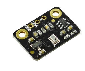
This sound sensor based on an omnidirectional MEMS microphone delivers an analog voltage based on the sound level.
Power Supply: 3.3 to 5 VDC
Connectors: Male connectors
Dimensions: 18 x 12.5 mm
MKR WAN 1310 card to interface sensors and send data via the Lora network

The Arduino MKR WAN 1310 board is equipped with a SAMD21 processor (Cortex M0+) and a LoRa interface, making it a very interesting board for IoT projects due to its low power consumption and LoRa connectivity.
The LoRa protocol is a low-rate wireless network that uses a frequency of 868 MHz, allowing for extended range for connected objects in a large part of France. Moreover, the configuration of this protocol is simple and energy-efficient.
The MKR WAN 1310 version includes a 3.7 VDC LiPo/Li-Ion battery charger with a JST connector and an SPI Flash memory in addition to the previous version, the MKR WAN 1300. The board can be programmed via its micro-USB port.
We utilized an Arduino MKR 1310 microcontroller and several libraries, including MKRWAN, Arduino Low Power, Adafruit EPD, etc to gather data from the CO2 sensor. Daytime updates are shown on the screen, and after collecting enough data, it is sent via LoRaWan for efficient and accurate data collection.
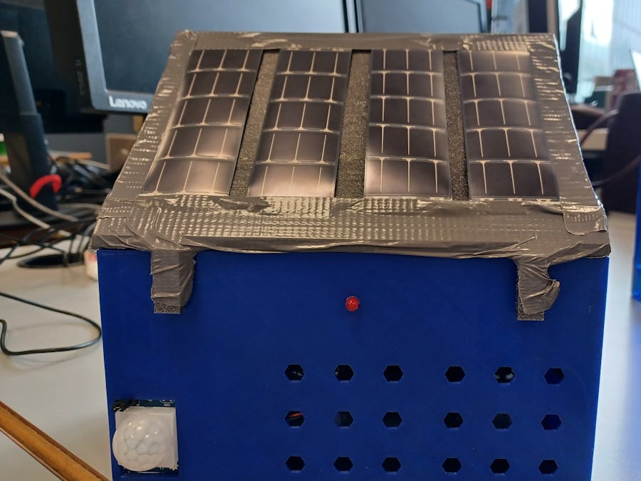
Our system is autonomous (Low Power Consumption):
The system is self-sufficient, this posible by using components and limiting the system's consumption.
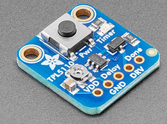
Components used include:
3.7 VDC 1000 mAh LiPo rechargeable battery (L903759)4 solar panels Timer to cut off the circuit and limit consumption. We utilized a TPL5110 timer module to conserve energy. This enabled us to activate the CO2 sensor only once every 10 minutes, which significantly decreased power usage and boosted battery longevity. As a result, it is well-suited for extended data collection without the necessity of recharging the LiPo battery. Additionally, we incorporated two indoor solar panels that greatly powering the device during daytime operation. Use of low-power consumption sensors Switch to turn off the system during holidays for example
Presentation of results :
We have decided to present our results on a user-friendly and intuitive website. In fact, that's why we have chosen to do it on Ubidots.
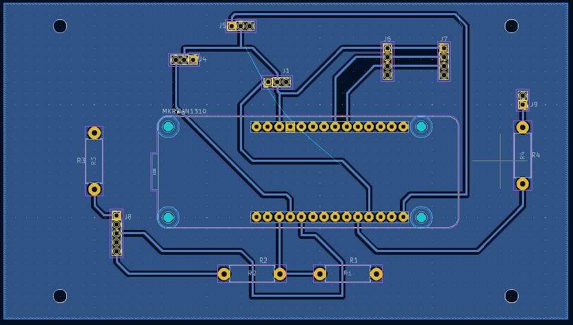
Schematics
General Schematic
PCB_schema
Routing_PCB
Code
Final
Arduino
#include <MKRWAN.h>
#include <DHT.h>
#include "Arduino.h"
#include "ArduinoLowPower.h"
#include "Adafruit_CCS811.h"
#include <BMP388_DEV.h>                           // Include pour le capteur de pression BMP388_DEV.h

BMP388_DEV bmp388;       // Instantiate (create) a BMP388_DEV object and set-up for I2C operation (address 0x76) on a modifi dans la bibliothque BMP388_DEV.h
Adafruit_CCS811 ccs; //Cre une instance de la classe Adafruit_CCS811 appele ccs


// Pin pour la lecture du capteur
#define DHTPIN 2

// Type de capteur
#define DHTTYPE DHT11

// Dclaration du capteur
DHT dht(DHTPIN, DHTTYPE);

// Objet LoRaWAN
LoRaModem modem;

// Identifiants de l'application TTN
const char *appEui = "0000000000000000";
const char *appKey = "D48686E9120D86ECB0DA89D310A90F99";

int fenetre =50;// en ms
unsigned int tension; //lecture de la tension
double niveau = 0; // niveau sonore en decibel

void setup() {
  pinMode(A5, OUTPUT);// Pin du timer
  pinMode(LED_BUILTIN, OUTPUT);// POur l'horloge  ===> Sleep Mode ncessaire

  // Initialisation du port srie
  Serial.begin(9600);

  // Initialisation du capteur humidit et de temprature
  dht.begin();

  // Initialisation du capteur humidit et de temprature
  bmp388.begin();                                 // Default initialisation, place the BMP388 into SLEEP_MODE
  bmp388.setTimeStandby(TIME_STANDBY_1280MS);     // Set the standby time to 1.3 seconds
  bmp388.startNormalConversion();                 // Start BMP388 continuous conversion in NORMAL_MODE

  // Initialisation du modem LoRaWAN
  if (!modem.begin(EU868)) {
    Serial.println("Erreur d'initialisation du modem");
    while (1);
  }

  pinMode(1,OUTPUT); //Rgle la borne numrique numro 1 de la carte Arduino en mode sortie (Lecture du pourcentage de la batterie)

  pinMode(5, INPUT);// Pin du capteur de prsence


  // Connexion au rseau LoRaWAN
  if (!modem.joinOTAA(appEui, appKey)) {
    Serial.println("Erreur de connexion au rseau");
    while (1);
  }
    if(!ccs.begin()){ // message d'erreur si capteur pas dtect
    Serial.println("Echec detection capteur CCS811");
    while(1);
  }

  while(!ccs.available()); // Attente que le capteur soit pret et que des donnes soient disponibles
}

void loop()
{
  digitalWrite(A3,LOW);
  // Lecture de la temprature et de l'humidit
  uint16_t humidity = dht.readHumidity() * 100;
  uint16_t temperature_dht = dht.readTemperature() * 100;

  // Vrification de la lecture du capteur
  if (isnan(temperature_dht) || isnan(humidity))
  {
    Serial.println("Erreur de lecture du capteur DHT11");
    return;
  }

  // Mircrophone pour la mesure du bruit
  unsigned long timer_start = millis();
  unsigned int tension_peaktopeak = 0;
  unsigned  int signal_max =0;
  unsigned int signal_min =1024;

  while (millis()-timer_start<fenetre)
  {
    tension = analogRead(A2);

    if (tension<1024)
    {
      if (tension>signal_max)
      {
        signal_max=tension;
      }
      else if (tension<signal_min)
      {
        signal_min=tension;
      }
    }
  }
  tension_peaktopeak = signal_max-signal_min;

  double volt = (tension_peaktopeak*5.0)/1024;
  double vp = volt/2; // tension crete  crete
  double v_rms = vp/sqrt(2); // valeur efficace RMS
  double PA_RMS = v_rms/66; // Pression accoustique en valeur efficace / sensibilit du microphone ou gain
  niveau = 20*log10(PA_RMS/0.00002)+20; // pression accoustique de ref
  uint16_t Niveau_envoie = niveau * 100; //conversion du bruit en uint16_t
  uint16_t co2;

//Capteur de Co2
do {
  if(ccs.available()){ // Si donnes disponible
    if(!ccs.readData()){ // Si donnes lus avec succs
      co2= ccs.geteCO2(); //utilise la fonction geteCO2 de la librairie Adafruit_CCS811
    }
    else{ // Si chec de la lecture des donnes
      Serial.println("Erreur lecture capteur Co2 !");
      while(1);
    }
  }
  ccs.setBaseline(0xE6BA);// baseline cu capteur C02 /
}
while (co2<350); // on a remarque que la premire mesure etait parfois fausse... On a donc dcid de mettre cette conditionc

// Capteur de pression
  uint16_t pression;
  float temperature, pressure, altitude;            // Create the temperature, pressure and altitude variables
  if (bmp388.getMeasurements(temperature, pressure, altitude))    // Check if the measurement is complete
  {
    pression=pressure;
  }
  else{ // Si chec de la lecture des donnes
      Serial.println("Erreur lecture capteur pression !");
    }

  // capteur de prsence
  uint16_t presence = digitalRead(5);// pin 5 pour le capteur de prsence

//Lecture du pourcentage de la batterie
  float batterie = analogRead(A1); //valeur analogique
  const float TensionMin = 3.6; //tension min
  const float TensionMax = 4.2; //tension max

  int minValue = (1023 * TensionMin) / 5; //Arduino
  int maxValue = (1023 * TensionMax) / 5; //Arduino

  uint16_t batterie_envoie = ((batterie - minValue) / (maxValue - minValue)) * 100; //mettre en pourcentage
    if (batterie_envoie > 100) //max is 100%
    batterie_envoie = 100;

    else if (batterie_envoie < 0) //min is 0%
    batterie_envoie = 0;


  // Cration de la charge utile (payload)  envoyer
  byte payload[14];
  payload[0] = highByte(temperature_dht);
  payload[1] = lowByte(temperature_dht);
  payload[2] = highByte(humidity);
  payload[3] = lowByte(humidity);
  payload[4] = highByte(Niveau_envoie);
  payload[5] = lowByte(Niveau_envoie);
  payload[6] = highByte(co2);
  payload[7] = lowByte(co2);
  payload[8] = highByte(pression);
  payload[9] = lowByte(pression);
  payload[10] = highByte(presence);
  payload[11] = lowByte(presence);
  payload[12] = highByte(batterie_envoie);
  payload[13] = lowByte(batterie_envoie);

  // Envoi de la charge utile (payload) sur The Things Network
  modem.beginPacket();
  modem.write(payload, sizeof(payload));
  modem.endPacket(true);
  // Affichage sur le moniteur serie
  Serial.print("Temperature : ");
  Serial.println(temperature_dht/100);
  Serial.print("Humidit : ");
  Serial.println(humidity/100);
  Serial.print("Niveau de bruit : ");
  Serial.println(Niveau_envoie/100);
  Serial.print("Pression en mbar : ");
  Serial.println(pression);
  Serial.print("Presence : ");
  Serial.println(presence);
  Serial.print("Co2 en PPM : ");
  Serial.println(co2);
  Serial.print("Batterie : ");
  Serial.println(batterie_envoie);

  if (co2>1000)    // seuil d'alerte C02
  { // a clignotte pendant 10 Secondes pas plus sinon on consomme trop !
    int i = 0;
    while (i <8)
    {
      digitalWrite(1,HIGH); //le courant est envoy sur la borne 1, la LED  s'allume
      delay(500);
      digitalWrite(1,LOW); //On eteint la led
      delay(1000);
      i++;
    }
 }
  delay(2000);
  digitalWrite(A3,HIGH); //On coupe l'alimentation du systme
}
The article was first published in hackster, April 16, 2023
cr: https://www.hackster.io/505877/monitoring-air-quality-6a9fb1
author: LRaei, Mayer Abraham


