

Original Tutorial found here: https://www.hackster.io/projects/6148d2
Story
Hey 👋!
Has anyone reading this gone to college? Or how about to the grocery store right down the road? Or maybe a long walk to your job daily? Well, this may be something that will help you out!
Utilizing a regular scooter and a hoverboard motor (among other things), I have built a working e-scooter! This tutorial aims to help all those that have too much walking to do... say hello to the DIY e-scooter based on Arduino!
Purpose
College campuses are usually sprawling, with lots of walking to do to get from class to class. People just walk, or use bikes or e-scooters, but there is one thing no one uses; a DIY e-scooter! With college coming up this fall for me, I aim to do less walking, and more flying on my DIY contraption.
This scooter also has many other purposes, as it gets you around easily and quickly!
Part Selection
TheScooter
The scooter for this project is very important and needs several specific features.
High foot pad for battery space
Preferably wide handlebars for better control, but I could not find a scooter that had these
Large tires; 6 to 8 inches
Relatively easy way to attach new motor mount in exchange for the regular tire
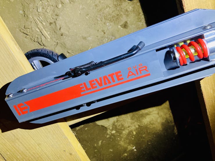
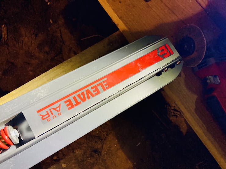
Now, with all these criteria, I have found one scooter (although there may be more) that matches everything except for the wide handlebars. This took me a lot of searching to find one that works for this! The scooter I used is a Mongoose Elevate Duo Air and can be found on Amazon.com here: https://www.amazon.com/gp/product/B09GJVTKN3.
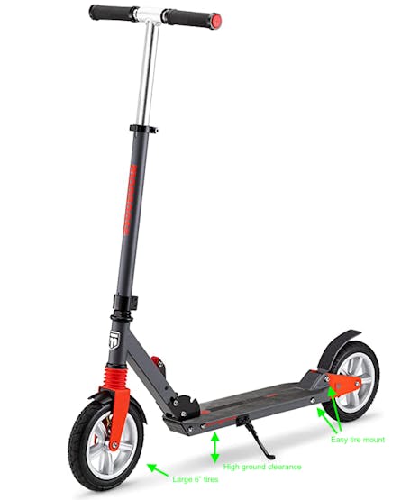
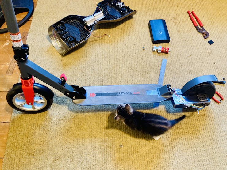
As you can see in the photo above, this scooter matches all the needed requirements!
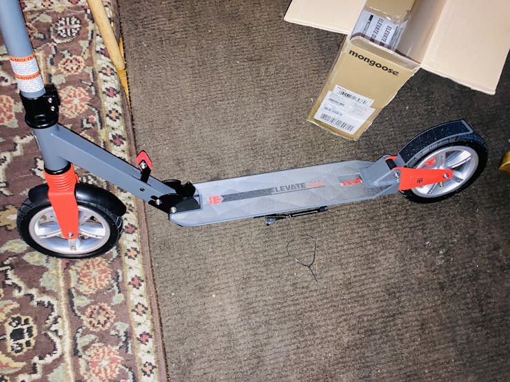
Here is me unboxing it:
The Motor
For motor selection, the motor can be fairly flexible, although there are some needed requirements:
36VDC motor voltage
Brushless DC motor (BLDC), hall sensors may be optional
The wattage can vary; the more watts, the more powerful though
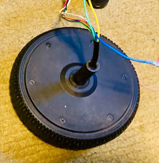
I have used a ~350watt repurposed motor from a broken hoverboard! Just in case you were wondering, the motor is actually inside the tire on hoverboards! This is quite unusual, as you usually see the two separated, but it is great for space saving.
Here is my motor / tire!
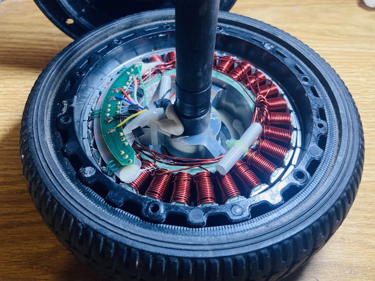
Here is a view inside the tire!
The Battery
The battery is very important! We have a size limitation due to the small space under the scooter, so the goal is to make it the biggest battery pack possible but still fit.
There are several requirements for the battery:
36VDC total nominal voltage (I used Lithium cells, so fully charged is 42V)
Max of 20 cells, as this is all that can fit under the scooter
Preferred capacity of 4AH or greater (I built mine as 5AH)
Discharge capable of 1.5x (minimum) the amperage draw of the motor (for a 350W 36V motor, that would be W/V = A*1.5 = 14.6A)
My battery I built myself, and it is made up of 20 3.7V Lithium 18650 cells. I chose the EVE INR18650/25p because of its discharge current and capacity. Here are my battery specs:
37V Nominal Voltage (42V fully charged)
40A Discharge Current
20x 18650 Cells
5AH Capacity
My battery pack I built:

I used a 42V5A charger to charge this battery. The max charge rate of lithium is 1C, which for a 5AH battery, would be 5A. So this charger would charge my battery from completely dead in only 1 hour!
The Motor Driver
Now, the motor driver is very important. Because this is a BLDC motor we are using, we need to find a driver capable of driving it! Some specifications we need for it:
≥ 36VDC Voltage
≥ 350W Driving Wattage
Brushless Motor Driver (most are for brushed motors)
If your motor has hall sensors, you will want the driver to be capable of hall sensors also, besides just the three phase wires.
I have yet to find a high quality BLDC motor driver that I can confidently endorse to you for this project. I am on my 5th motor driver currently, as all the ones I've tried have had issues!
This one seems to be the most reliable, although it brakes unexpectedly and doesn't go very fast:
https://www.amazon.com/gp/product/B08J7HNFDL
This one is my favorite, because of the high torque and high speed, but it stopped working suddenly for no apparent reason:
https://www.amazon.com/gp/product/B087M2378D
I also tried the ones listed below, but they have both stopped working for no apparent reason:
https://www.amazon.com/dp/B016O0B0MQ
https://www.amazon.com/gp/product/B08J7Y9QQ8
If anyone can find a high quality motor driver, please feel free to post in the comments! I would absolutely love any suggestions, as I am having a hard time finding a good BLDC motor driver.
How a BLDC Motor Works
So… there are two main types of DC (Direct Current instead of AC - Alternating Current used in house power) motors, the first being brushed and the second being brushless.
Now, the terms refer to how the motor is designed on the inside. Brushed motors are the most basic and are used in almost everything, from the kitchen blender, to the household vacuum. Brushless motors are usually used for more precise things such as drone motors, or hoverboard motors, etc. They are used in these applications because they are stronger (more torque), faster, and more precise than regular brushed motors. Brushed motors only have two wires, while brushless usually has either three or eight wires (depending on if there is hall sensors).
This makes brushless motors much more complicated to control. So complicated, in fact, that they usually need a designated driver specifically for them away from the main electronics. They work from turning a series of electromagnets (magnets that can turn on and off from electricity) on and off in a certain sequence. The stator (the outside ring) usually contains the electromagnets, while the rotor (interior ring) is made up of permanent regular magnets. If controlled correctly, the motor will spin from turning on and off certain electromagnets at certain times in the right sequence.
To control the 3 electromagnets, they need to be turned on and off with transistor pairs as seen below:
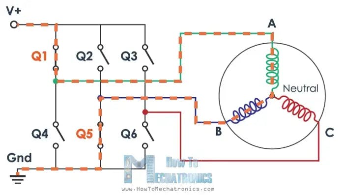
For more information on how BLDC motors work, and how to control them, check out howtomechatronics's tutorial found here!
https://howtomechatronics.com/how-it-works/how-brushless-motor-and-esc-work/
Here is two really informative GIFs on how a BLDC motor works!
How to Build the Battery
I chose Lithium 18650 cells to build my battery with, as this is fairly standard. The cell selection is very important; you need to make sure you meet all the requirements in the #Part Selection section above. I used 18650batterystore.com to shop for the cells, although there are many online battery stores that sell 18650 batteries!
Battery Configurations
My battery configuration is as below:
There are many different ways to configure a DIY battery pack! First, you have two main numbers; how many in series (labelled as "s"), and how many in parallel (labelled as "p"). The first number represents how many cells are in series, like below:
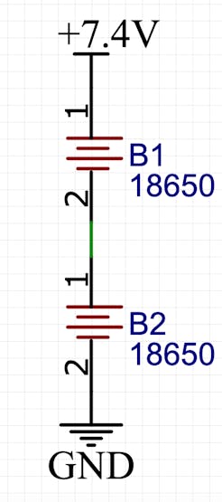
When two cells are wired in series, the voltage is added up, but the capacity stays the same. So for the above battery (if the cells were 3.7V and 2.5AH), it would be a 7.4V 2.5AH battery. The second number ("p") represents how many cells are in parallel, like below:
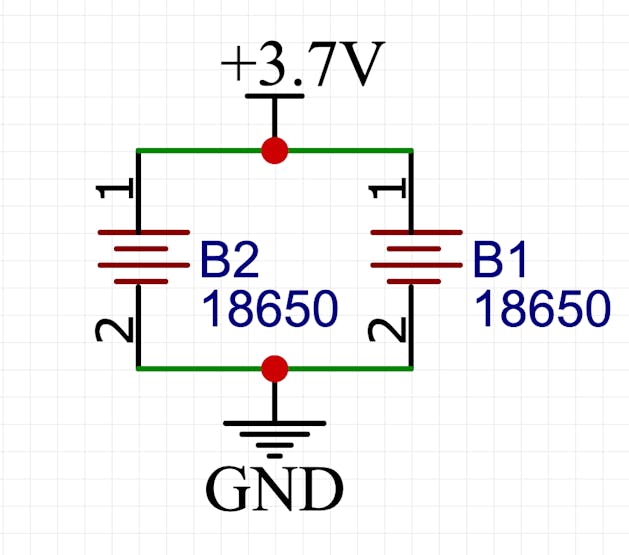
When two cells are wired in parallel, the amp-hours are added up, but the voltage stays the same. So for the above battery (if the cells were 3.7V 2.5AH), it would be a 3.7V 5AH battery.
Based on this information, my 36V battery configuration would be a 10s2p. The 10 in series makes 10*3.7 = 37V, and the 2 in parallel makes 2*2.5 = 5AH! Simple, right?
So... now that we understand battery configurations and how we can make a 37V battery from a lot of 3.7V batteries, let's move on to the build!
Things Needed for the Battery
First, we need to know the parts and the tools needed to build the battery.
Note: The amazon links are referral links, so I earn a small commission when you use them to buy the parts for this project!
Battery parts:
Battery tools:
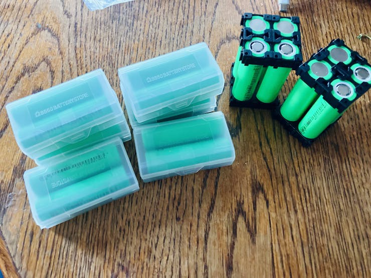
SpotWelding the Battery
The first step in building the battery is to put all the spacers on the cells. The end goal here is to end up with 5x 2x2 squares of connected 18650 cells like shown in the photo above. Notice the polarity relative to the location for each cell; this is very important!
Now that you've got your cubes put together, it's time for welding!
Don't worry, spot welding isn't very complicated. Below is a short demonstration on a blank cell.
See? Not so bad!
It took me several tries on blank cells to figure out the easiest way to connect the cells together correctly. I found the best way is to place two of the cubes standing up next to each other, and spot weld two strips across the top as seen below:
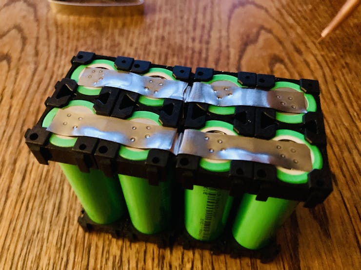
Take careful notice to the polarity of each cell in the photo above.
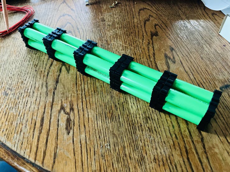
Once two are welded together, you can simply fold it, and this will create the right shape!
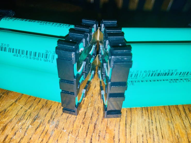
Continue spot welding and folding as seen above, until you have one long strip like here:
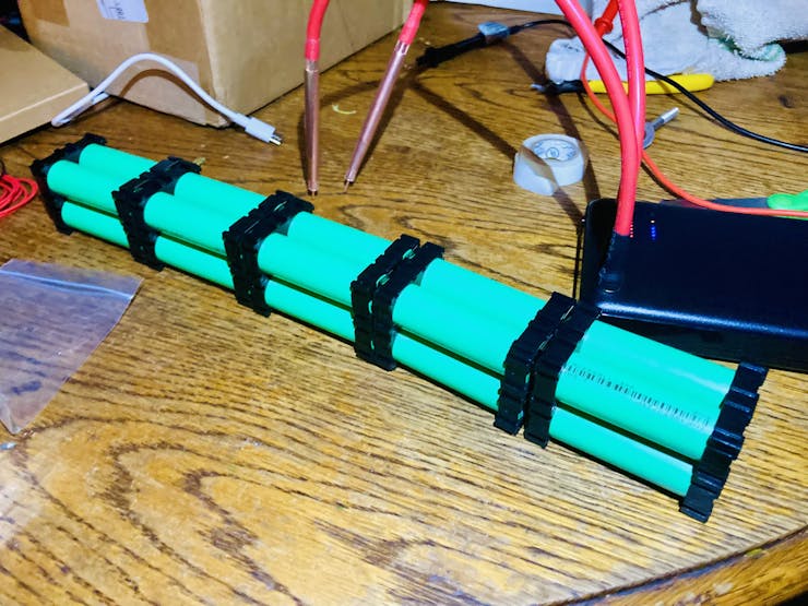
Here are the two battery ends; one is completely welded together, and the other side has the positive and negative terminal.
Spot welding is complete!
BMS Installation
First, tape just the BMS connector to the battery, being mindful of the BMS's placement.
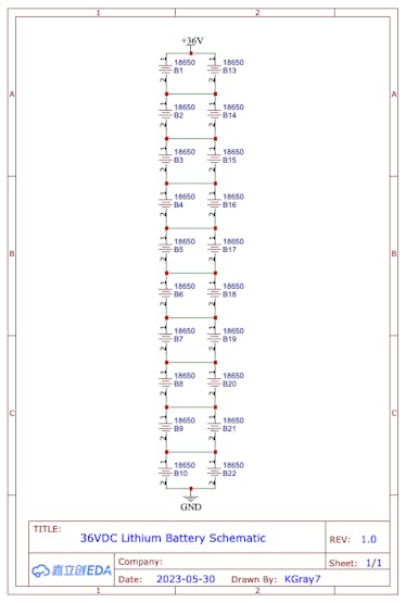
Once taped, each BMS wire has to be soldered in the correct place. You can se in the photo above, I have already soldered the first three. You start with the black wire (negative) and solder it to the negative terminal of the battery. From then on, each red wire is soldered onto each battery terminal as the voltage increases.
If my explanation sounded too convoluted, here is the schematic:
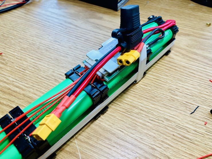
Below is the battery with its completed spot welding and the BMS connector finished!
Soldering the Power Connectors
This battery will need two connectors; one for charging and a separate one for discharging.
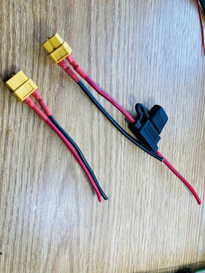
Make sure to have the fuse; without it, bad things can happen! I used a 20A fuse in my fuse holder, because I calculated he max current draw to be ~14A. A good rule of thumb for fuse amperage is 1.5x the max current draw of the project.
When soldering the power connectors on, make sure to have the fuse inline on the positive discharge cable! Also make sure to solder the charge and discharge negative wires to the correct ports on the BMS; DO NOT SOLDER ANY POSITIVE WIRES TO THE BMS EVER! I learned this the hard way, because I wasn't sure what to solder where. The negative charging cable goes to "C-", the negative discharge cable goes to "P-" and the battery negative port goes to "B-".
Wrapping the Battery
Now that everything is wired, it's time to wrap! I used 103mm blue shrinkable battery wrap from Amazon. First, unroll some and cut it the length of the battery, but with an extra 5 inches on both ends. Measure and cut a hole for the power connector, and slide the battery into the wrap until there is an even amount of extra wrap on both ends. Now, it needs to be heated!
I was going to buy a Dewalt heat gun from Home Depot, but that would be so boring! So I bought a soldering iron / hot air soldering station from Amazon, and I use both all the time. Set the hot air to ~400˚ (if its too hot, it will melt holes through the plastic). To shrink it correctly, you will need to run the heat gun down up and down the battery, slowly but steadily, over and over. To get an even application, try alternating location; so heat a line down the top of the battery, then flip it over and do so on the bottom, then maybe the left then right, and so on.
After it looks like you have finished shrinking it, wait for it to cool, and give it another once over with the heat gun. I have found that after it has cooled, there has been more space to shrink. The wrap doesn't shrink all the way around the ends of the battery of course, so I just heated the wrap all around the end, and then, while it was still hot, folded it over and pressed it flat until it cooled, that way it retained its shape!
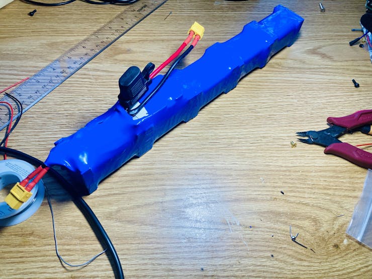
The battery is done!
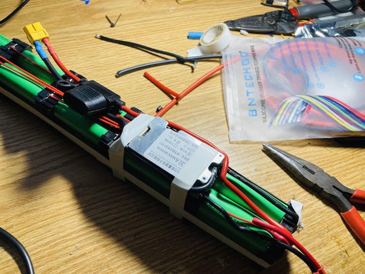
UPDATE:
I actually ended up rewrapping the battery, because the fuse holder didn't fit into the bottom of the scooter! I re-soldered the connectors like this:
Modifying the Scooter; Battery Space & Back Tire Removal
The scooter needs some modification of course to change it to electric! First, a space needs to be made for the battery pack.
Tools needed:
Grinder with cutting disk
Face shield / goggles
Ear protection (optional)
Protective clothing (required for welding)
DISCLAIMER: Make sure to perform modifications in a safe environment with sufficient eye and ear protection on. This scooter is aluminum, so the metal shards from cutting will not glow, but they are still there.
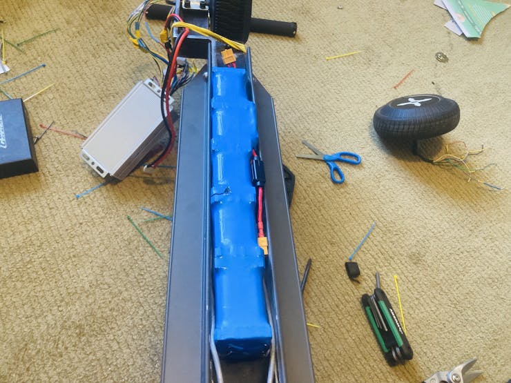
Making Space for the Battery
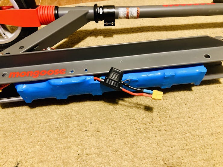
First, the bottom plate needs to be removed. So place the scooter on suitable saw-horses or similar, and cut out the bottom metal plate very carefully; try to get as close as possible to the side walls, as we need as much space as possible for the battery.
The battery now fits!
Removing the Back Wheel
The back tire and bracket can be removed in one piece by only removing two bolts! Using the Allen wrench, unscrew the two bolts holding the back tire assembly on; make sure to hold on to those bolts! The whole back should come right off!
Modifying the Scooter; Back Tire Rebuild
Tools needed:
Grinder with cutting disk and sanding disk
Face shield / goggles
Protective clothing
Ear protection (optional)
Welder
Materials needed:
Right angle metal for rear motor/tire bracket
DISCLAIMER: Make sure to perform modifications in a safe environment with sufficient eye and ear protection on. This scooter is aluminum, so the metal shards from cutting will not glow, but they are still there.
The third modification / addition, is a mount for the hoverboard motor! I made it as simple as possible so it would be easy to follow along with me.
First, measurements!
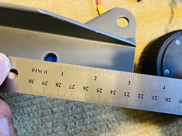
So, the bracket will extend three inches into the back of the scooter, to be able to be bolted in. Also, there will be 5 inches from the front of the bracket to the back of the bracket for where the tire sits.
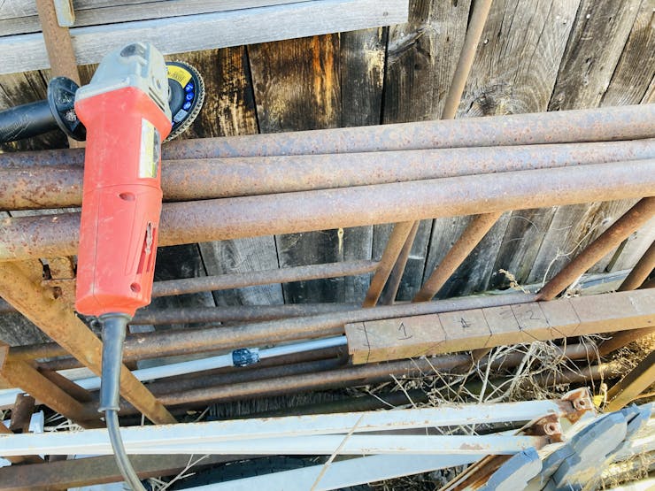
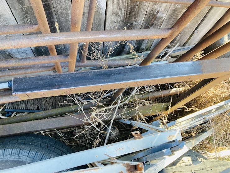
I found some old metal, and got started cleaning it up!
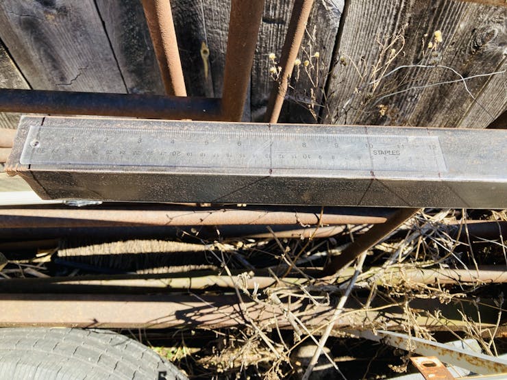
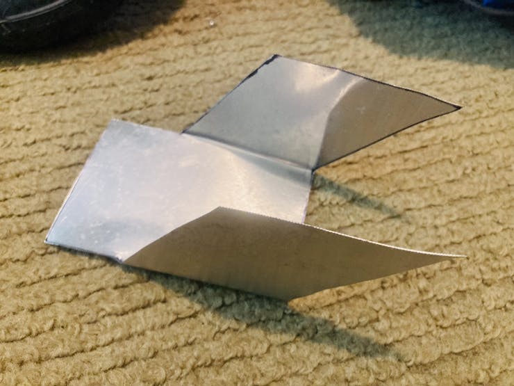
Now time to mark! On the top of the metal (where the top of the bracket would be), take a ruler and sharpie marks at 7", 10", and 12". On the bottom of the metal, make sharpie marks at 5", 10", 12", and 14". Now, draw straight lines between the measurements as shown in the photo below:
Now, cut out the bracket pieces!
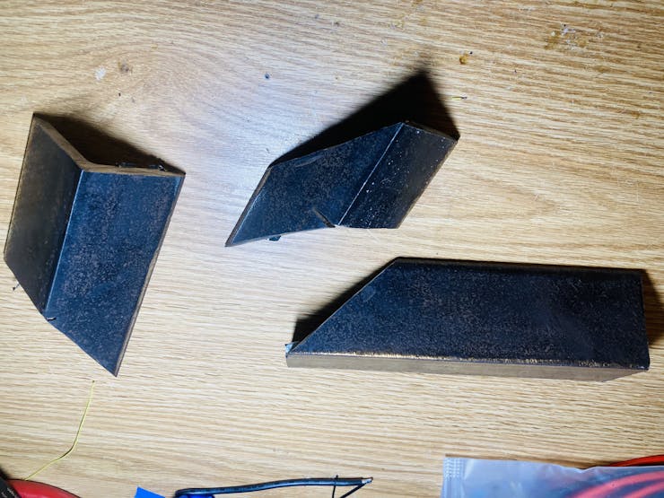
Also, I found that the medium size piece needed to be trimmed on one part, to fit into the scooter better:
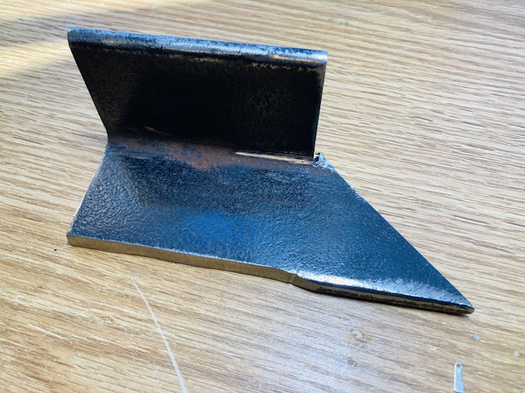
Time to try it out!
Looks good!
More photos of bracket pieces:

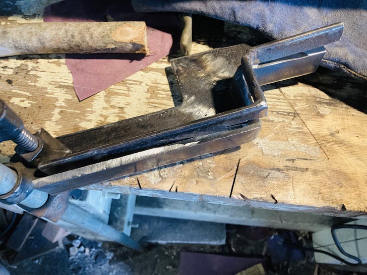
Now, time to weld!
A bit of advice: When welding, you have to be extremely careful! A welding mask is a must, along with clothes that you don't want to get ruined.
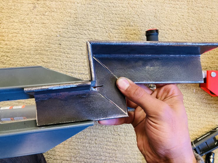
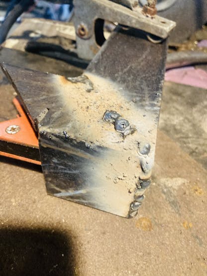
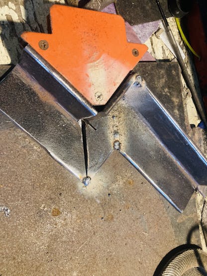
First, lay out the bracket pieces on your work space how they would go together. Now, take two, and somehow secure them down; I used a right angle magnet specifically used for such jobs, and this securely held two bracket pieces together at the right angle!
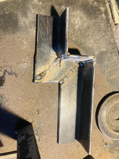
Now weld the second joint:
Use the magnet again to weld the last piece on:
As you can see in the photos, my original cuts didn't end up being the straightest, although I tried. It doesn't matter though when you weld it.
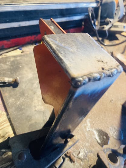
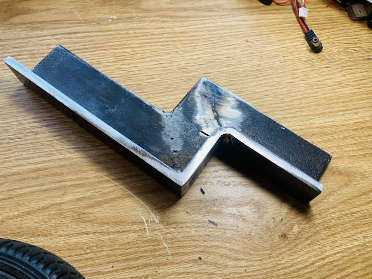
Finished welding!
Now time to clean up!
Put a fairly rough sanding disk on your grinder, and get to work! I had a lot of work to do, as my welding is atrocious.
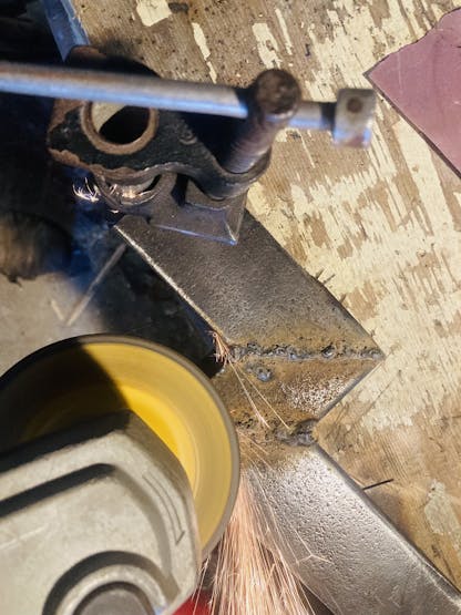
Now that the sanding is done, the bracket needs to be trimmed again; so get that cutting disk back on the grinder.

Mark 1.5" down all the way along the bracket, and cut along the line!
Finished welding, cutting, and cleaning up!
Now, time to drill the holes!
The motor mounting bracket uses 4x bolts to secure it. Also, the motor itself requires a much longer hole for the main shaft. The part that slides under the scooter needs a hole too for attaching it in replacement of the previous tire bracket.
I used the bracket to mark the holes; just place it in the correct spot and sharpie mark in each hole!
Tip: Use water when boring the holes! The drill bit may get very hot and snap if you do not.

And... turn this:
Into this!
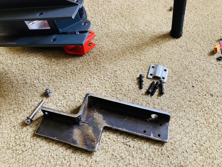
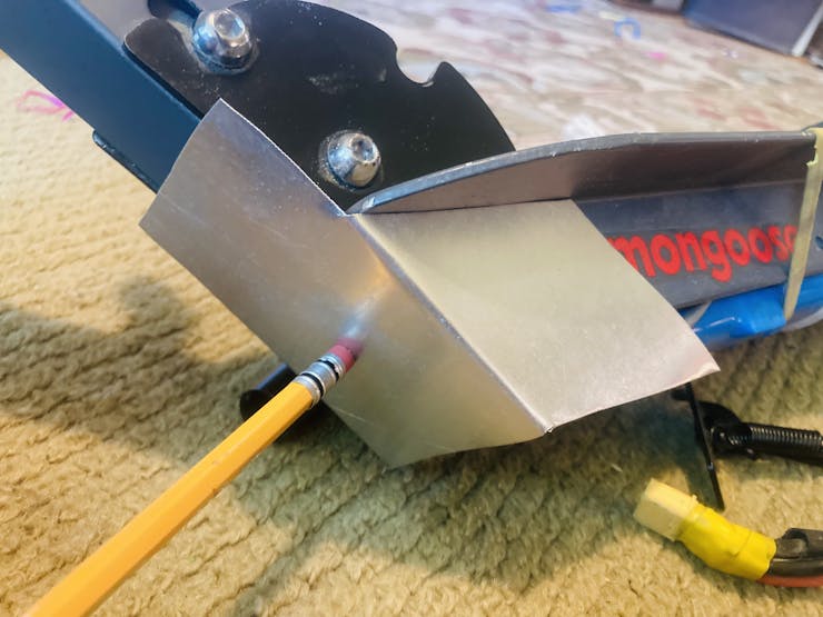
If you notice in the photo above though, the bracket is only attached to the scooter with one bolt! So, I decided to weld a triangle shaped metal piece to the top of the bracket, for a second bolt to go through.
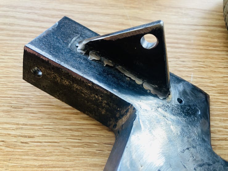
I also drilled two holes right after the add-on piece, for securing the original mud guard! So, the finished bracket attached to the scooter looks like this:
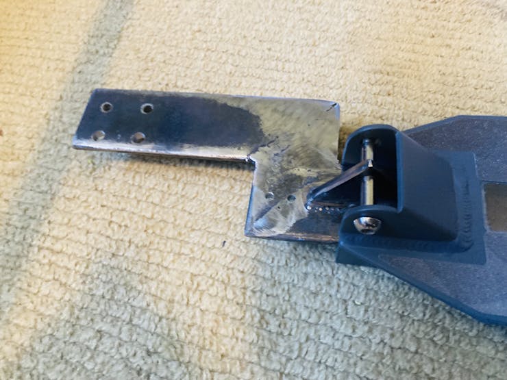
Mud guard:
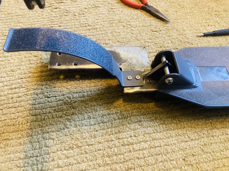
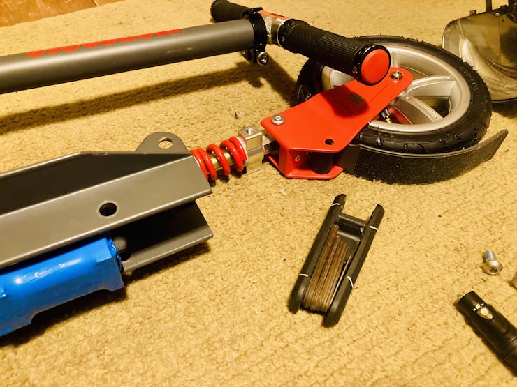
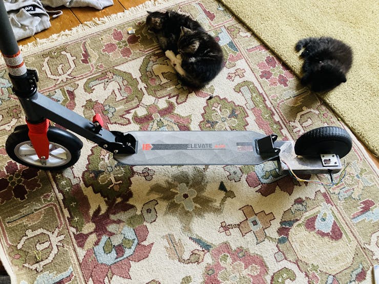
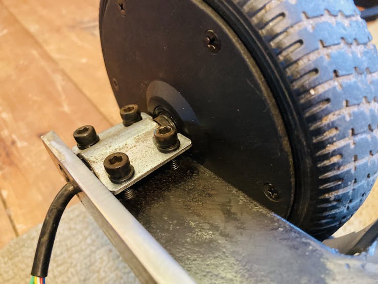
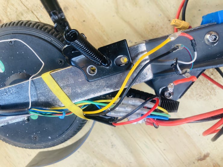
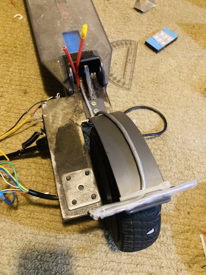
Here's the entire rear tire and mount!
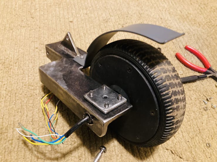
And we are back on two wheels finally!
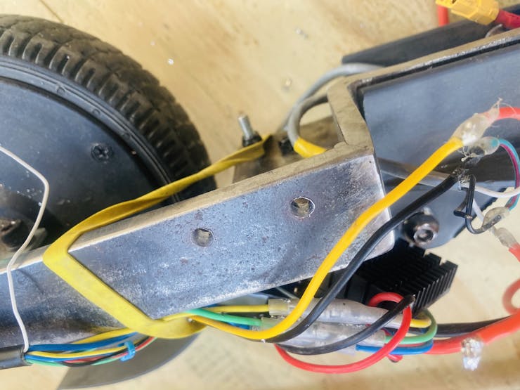
Here is a view of how the motor is mounted to the bracket:
Modifying the Scooter; Cable Running
Tools needed:
Grinder with sanding disk
Face shield / goggles
Ear protection (optional)
Drill with boring bits for metal
Materials needed:
Wire (I used 2x 18/4 cables, so 8 wires in total)
DISCLAIMER: Make sure to perform modifications in a safe environment with sufficient eye and ear protection on. This scooter is aluminum, so the metal shards from cutting will not glow, but they are still there.
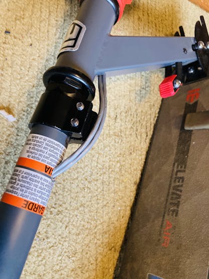
This is the fourth and final modification. We have to run the cables from the display, all the way down to the motor!
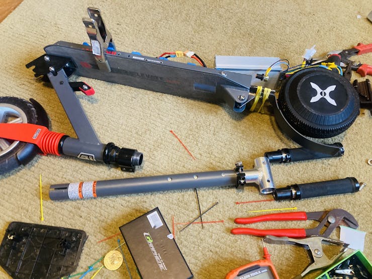
First, unscrew the handlebars... the entire thing!
The handlebars pole will need two holes. Drill one right beneath the top, and at the bottom in the exact place I did (notice the warning sticker). I drilled here, because this is right above the black screw in that is on the scooter body.
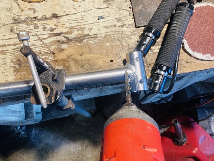
Now, the scooter body needs only one hole; drill it right after the fork that goes down to the front tire and up to the handlebars.
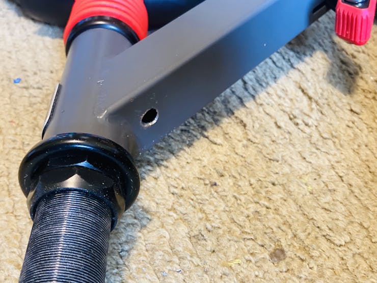
Grind all these holes smooth, to prevent the sharp metal from cutting the cable.
Now time to run the cables! This took me quite a bit of time.
First, measure an approximate distance for the cables, down the handle bar, across the foot bed, to the motor. Make sure to give yourself extra length, you don't want to have to redo it!
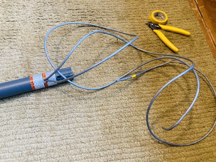
Run the two measured cables through the first hole on the handlebars pole all the way, until you only have a little sticking out.
I marked one with yellow tape, so I would know which one is which by the time I got to the motor.
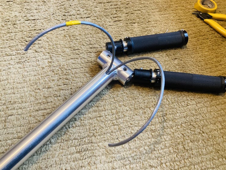
Fish both cables up through the second hole in the handlebars.
Screw the handlebars back onto the scooter now
Now, put the wires through the third and final hole on the scooter base.
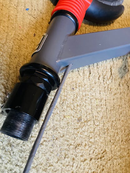
Now just lay the wires across the base (I placed them under the battery).
That's it!
DFRobot
DFRobot is amazing! They are an electronics company who makes many, many different parts and modules. Anything from their new Offline Voice Recognition Module and FireBeetle 2 with camera, to an Ultrasonic Material Detection Sensor, I have found and used many innovative parts from them! They design and build the parts themselves, and I have found the quality to be exceptionally good. Documentation is very well done for each part, customer service is very responsive. Check them out here!
The Circuit
Now, on to the electronics part of the project!
For this project, since it is a bit more complicated than my usual projects, I made sure to add everything that I would want plus some!
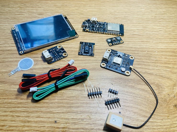
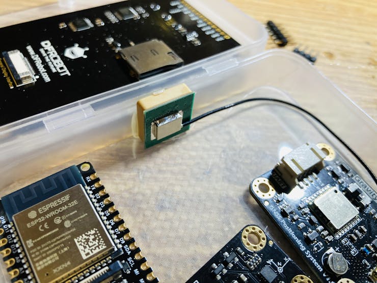
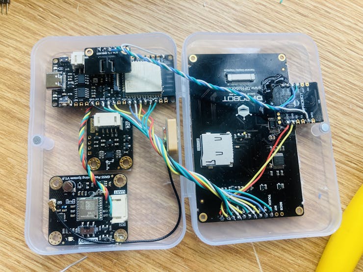
I use a accelerometer for determining current slope angle, a AHT20 for temperature and humidity, DFRobot's new GNSS module for high accuracy positioning, a pressure sensor as the throttle, a 2.8" touch screen to display all the info, and a gesture sensor for changing settings and locking / unlocking the e-scooter!
Components needed:
350W-500W BLDC Motor Driver/Controller (See Motor Driver section in "Part Selection")
USB-C Cable for ESP32
On-Off Switch
10kΩ, 1kΩ, 15kΩ resistors (1 of each)
Here are all the parts:
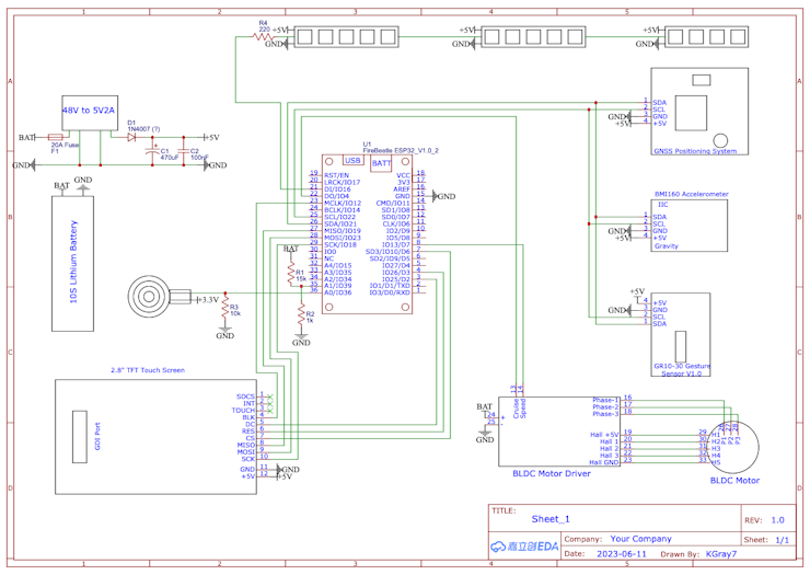
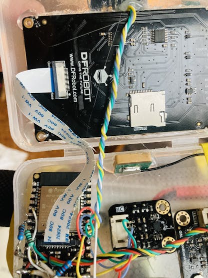
The diagram is fairly simple, as most of the components use I2C! The display can either be wired as in the schematic, or you can use the GDI cable. I chose the GDI cable as it is so much simpler to do. Just plug it into the display, and into the ESP32, and wallah!
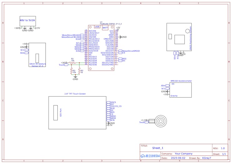
And here is a wiring diagram!
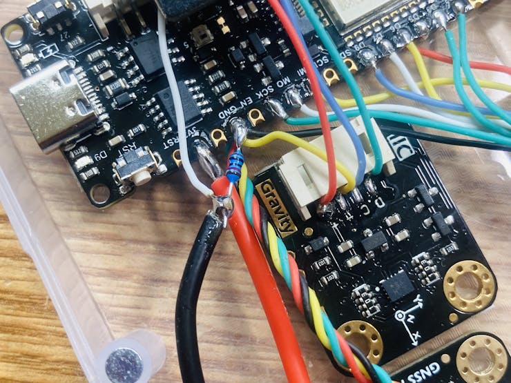
UPDATE:
The motor driver I used actually ended up needing 5V to fully turn on, and the ESP32 only provides 3.3V! So, with a transistor and a few resistors, I fixed that.
The circuit below is the added speed signal circuitry to have 5V when fully on, instead of 3.3V.
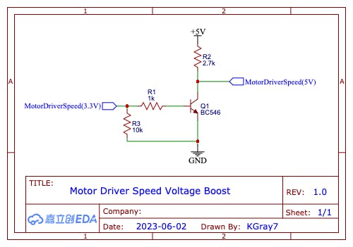
The one downfall of this circuit, is that the output is reversed! So if the input is 3.3V, the output would be 0V, and if the input is 0V, the output will be 5V.
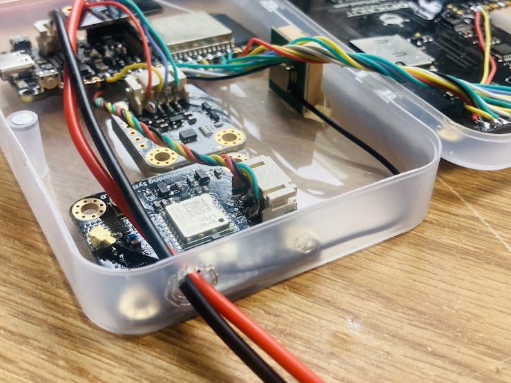
Assembling the Electronics
Now time to put everything electrical together!
First, cut measure and cut out an opening in the top of the case for the touch screen to fit through.
Now, place the rest of the components (besides the motor driver and voltage regulator) in the case, in a manner that works. I decided on the below:
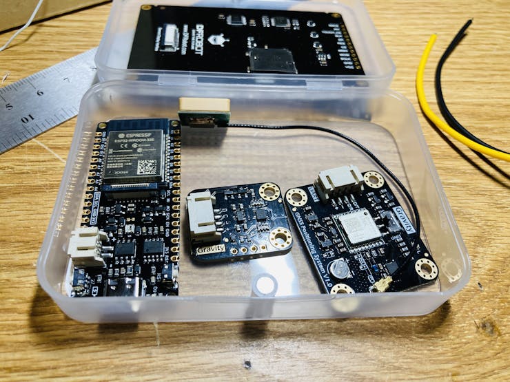
Once you like their placement, hot glue them down!
Now, time to solder...
I soldered the AHT20 to the FireBeetle first.
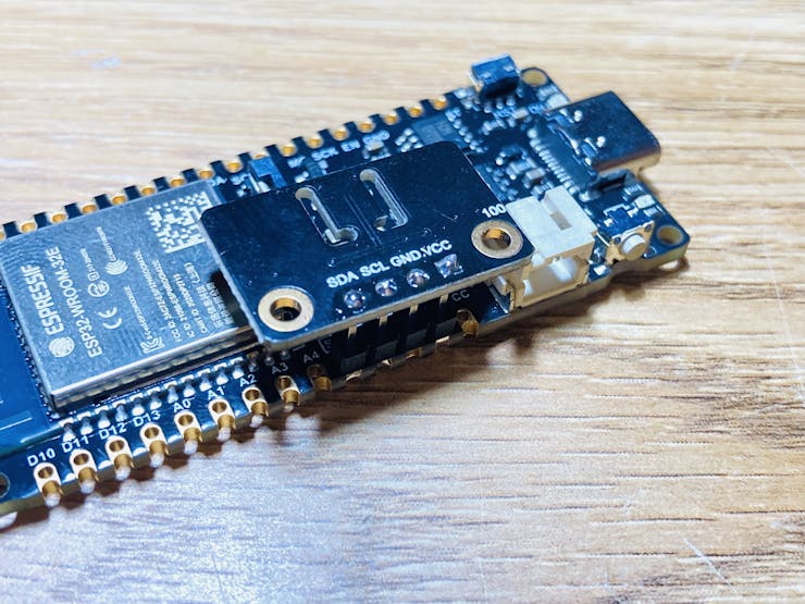
Although this works and is very simple, the temperature will always be a little high, because of the heat from the ESP32.
Soldering the display to the FireBeetle takes a lot of wires!
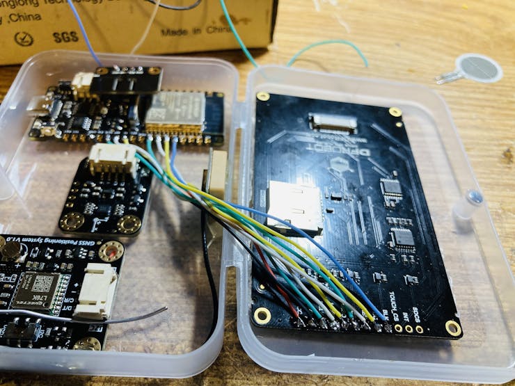
I did that at first, but when I had to replace the display (due to me short-circuiting it), I just used the GDI.
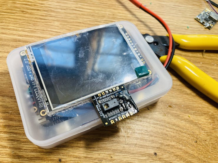
Now the GPS and gesture sensor. The gesture sensor cannot be placed where it is in the photo below, as the results are not correct!
I ended up placing the gesture sensor outside the case, right under the display.
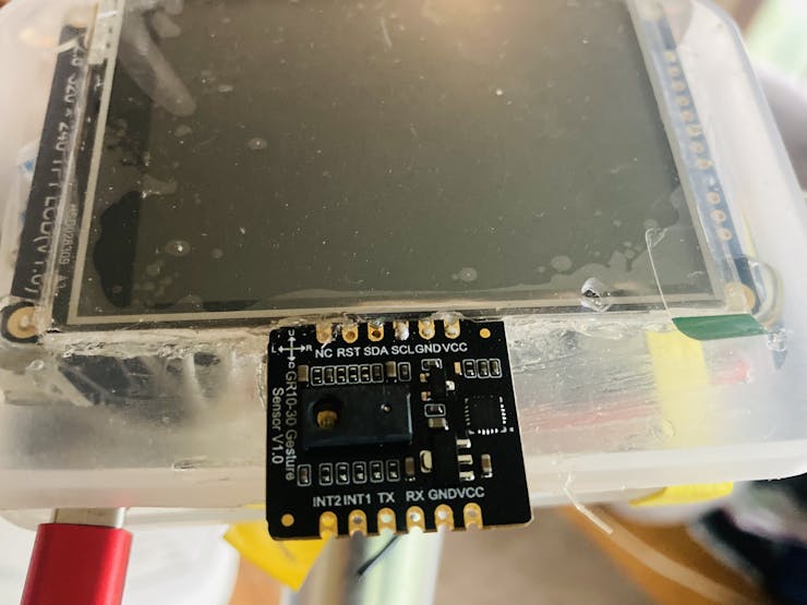
It is very vulnerable to damage like this though, so I melted a thin layer of hot glue over everything except for the transmitter/receiver on top, to protect from short circuits and such.
The accelerometer is I2C, so it is attached to the same 4 pins as the GPS and gesture sensor.
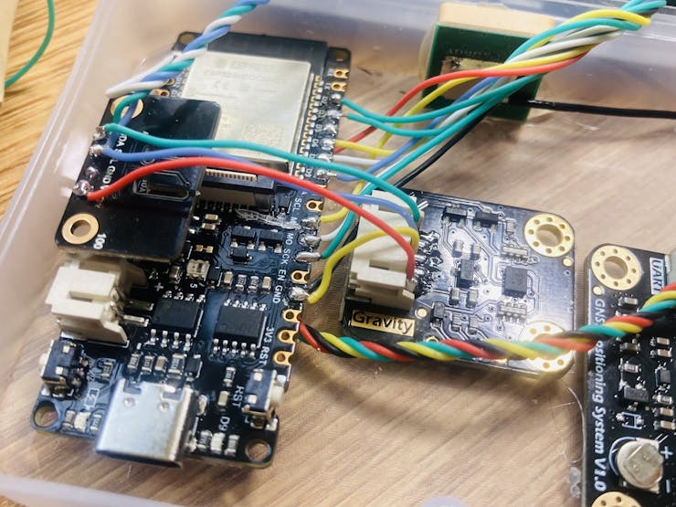
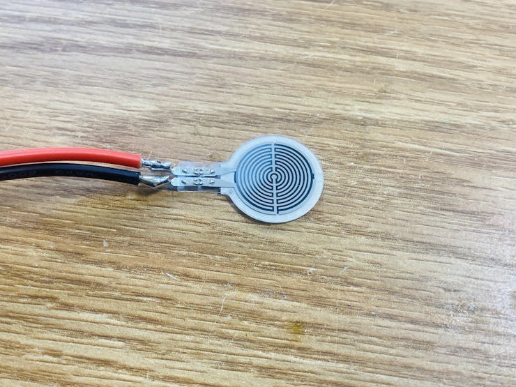
For the pressure sensor, I soldered to it two 20awg silicone wires for flexibility, and put heat shrink around the connections to protect them.
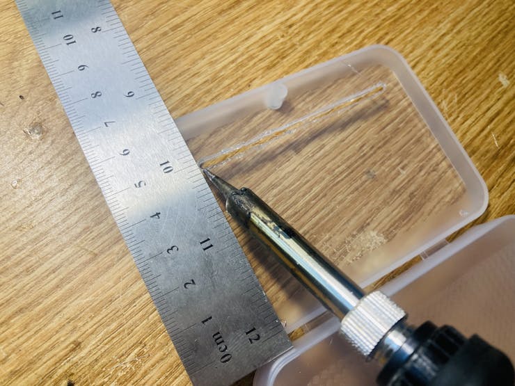
I ended up melting a hole in the side wall of the container above the GPS, using the soldering iron.
The red gets soldered to 3.3V, and the black gets soldered, to a 10kΩ resistor which then goes to GND. A wire from the analog input (white) is soldered to the black pressure sensor wire, before the resistor. This creates a voltage divider, with the pressure sensor as one of the resistors!
Full case done! The gesture sensor is now on top too.
Now all you have to do, is upload the code!
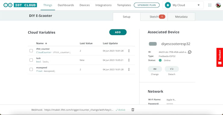
Arduino Cloud
Time to setup the Arduino Cloud!
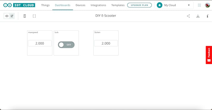
For this project we'll need to setup a "Thingy", three "Widgets", and a "Webhook".
First thing's first; let's setup the "Thingy"! Go to https://create.arduino.cc and click on "Things". Add a new one and name it something cool. Now, add a new variable and name it "lock". Set it as a "bool" with "Read / Write" permission. Now add another one called "maxspeed"; this will be used to set the speed limit! Set it as a "float" with "Read / Write" permission. The last variable is to be called "ifttt_counter" as it is for the stolen alarm. It's type is "Counter", and has "Read / Write" permission.
Now that the variables and thingy are set up, time for the dashboard! Add three widgets; one for each of the variables. The "ifttt_counter" and "maxspeed" should be numbers, while the "lock" is a switch.
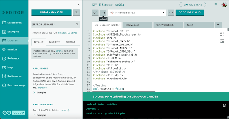
That is it! Now, to upload the code, first go to the "Things / Sketch" section. Then click on the "Open Full Editor" button at the top. Paste the code from the GitHub repository into the sketch, making sure the sketch is empty first. Before hitting the upload button though, all the libraries need to be added! So download the code in the GitHub repository, and go back to the Arduino Online Editor. Click the "Libraries" button to the left, and then click the "Import" button at the top.
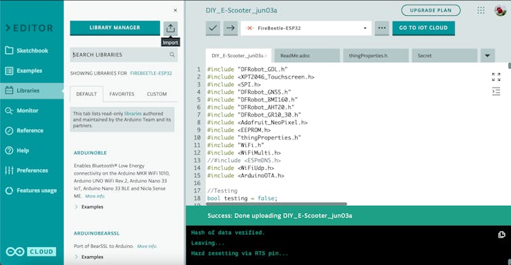
Select the downloaded file from GitHub that is called "DIY_E-Scooter Libraries.zip", and click import. Now you can click the upload button! Just make sure you have the right board and port selected.
To setup the web hook for "Stolen" notifications, follow this tutorial to a tee; all the names I used and everything are identical!
Now, when your scooter is moved while it is in "locked" mode, you'll get this notification on your phone!

The Lock button may be used now to lock / unlock your e-scooter remotely, and the maxspeed can be used to set a speed limit for yourself!
Code Breakdown
Please check the Hackster tutorial for this section!
Bonus Add-ons
After my first test run, I quickly realized I would have to protect the battery in some way! It also needed a "mud" guard on the front end, because there was lots of dust and debris on the battery under the front part. I also decided to add a kickstand, and some LEDs for turning signals and brakes!
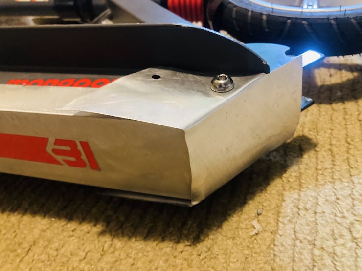
Mud Guard
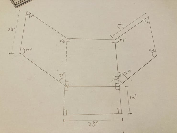
So I started on the mud guard first!
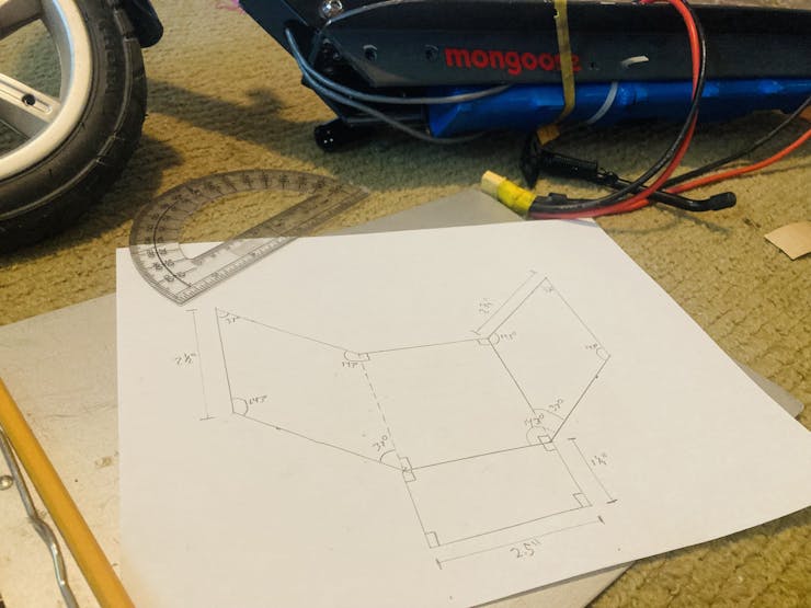
This took me several tries because of the angles, but I did get a working template down!
Here is my first failed try:
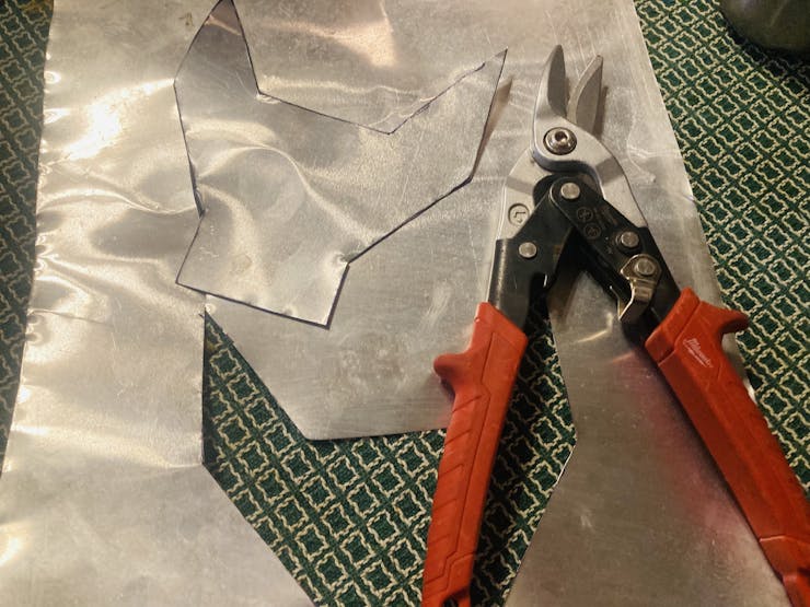
And here is the correct one!
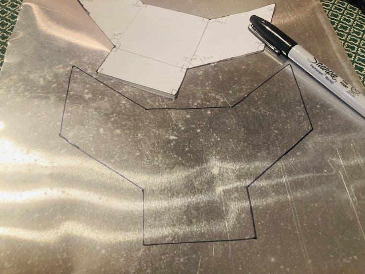
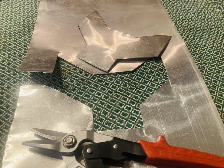
Done! Then I just added some holes and screwed it in!
Kick Stand
For the kick stand, I just reused the kick stand that I had to remove from the scooter for the battery!
After much deliberating, I decided to mount it on the bracket I made. So, I placed the kickstand on the bracket in a suitable place, and marked with a sharpie in the holes. Just drill them with a boring bit, and mount the kick stand!
LED Strips
For the LEDs, I used WS2812 strips! I decided to put one 5-strip on the back of the back mud guard.
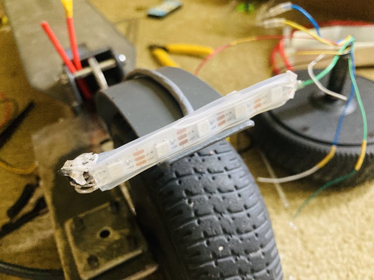
If you look where the wire goes above, it goes through a hole I drilled through my bracket! As you can see, there is also two red wires coming up through; I hooked these to a rocker switch for turning the scooter on and off.
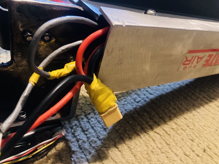
Battery Cover
For the battery cover, I found a perfect size piece of aluminum; after cleaning it up, and cutting it to length, here's how it looks!
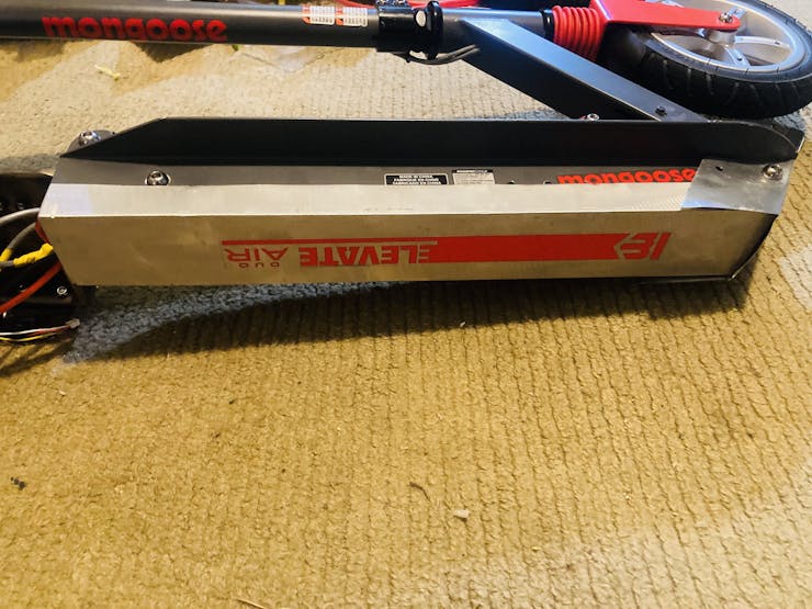
I reused the sticker from the previous piece of metal that was on the bottom!
Another view of the mudguard:
Backup Battery Connection
As a bonus, I also added an extra battery plugin for plugging in an extra backup battery!
Battery connector:
Results
Here are some GIFs of the display and a short video on the LEDs!
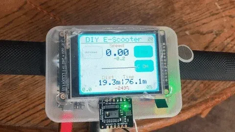
Here is my very first test run! I did it on a long stretch of almost empty sidewalk, and I tested uphill and downhill. My top speed uphill was 9kn and downhill was 15kn. The motor driver used in this test was the https://www.amazon.com/gp/product/B08J7HNFDL.
Wrapping Up
I hope you enjoyed my tutorial! I may not be the best explainer at times, but I try my hardest. If you don't understand a part, or have questions, feel free to post in the comments! Any thanks or compliments would be appreciated too. Well, till next time!
Check out my other tutorials here:


