The Story
Hello! I decided to build this project because ionizing radiation can be dangerous, and it is very hard to know if it's there. I am hoping this project will help people be able to create their own ionizing radiation detectors for relatively cheap!
How Ionizing Radiation Works
The definition of ionizing radiation is "radiation consisting of particles, X-rays, or gamma rays with sufficient energy to cause ionization in the medium through which it passes." This includes air, water, and living tissue. Ionizing radiation can travel unseen and pass through these materials.
Ionizing radiation is on the right of the scale below:
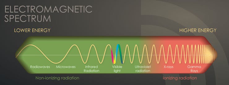
From: https://www.cdc.gov/nceh/radiation/ionizing_radiation.html
A easily recognizable form of ionizing radiation today, is that of x-rays, which can penetrate our body and reveal pictures of our bones. Ionizing activity can alter molecules within the cells of our body. That action may cause eventual harm (such as cancer). Intense exposures to ionizing radiation may produce skin or tissue damage.
There are 5 types of ionizing radiation:
• alpha particles
• beta particles• positrons• gamma rays• X-rays
Alpha particles are "positively charged particles consisting of two protons and two neutrons emitted from the nucleus of some radioactive atoms. An alpha particle is the nucleus of a helium atom. Unstable atoms with a low neutron-to-proton ratio may emit alpha particles."(Osha)
Beta particles are "negatively-charged, fast-moving electrons emitted from the nucleus of various radionuclides. Unstable atoms with a high neutron-to-proton ratio emit negatively-charged beta particles."(Osha)
Positrons are similar to Beta particles, but are positively charged. They are "positively-charged, fast-moving electrons emitted from the nucleus of certain radionuclides. Unstable atoms with a low neutron-to-proton ratio can emit positrons."(Osha)
Gamma rays are "high-energy electromagnetic photons emitted from the nucleus of an unstable, excited atom. Gamma rays are pure energy and can travel great distances at high speed."(Osha)
X-rays are "High-energy electromagnetic photons emitted from outside the nucleus. The primary difference between X-rays and gamma rays is that X-rays are emitted from processes outside the nucleus, but gamma rays originate inside the nucleus."(Osha)
Ionizing radiation particles (e.g., alpha, beta) or high-energy photons (gamma rays, X-rays) can travel different distances and interact with the atoms of absorbing materials in their paths, causing excitation or ionization of the atoms. As shown in the graphic below, while alpha and beta particles are not very penetrating through other materials, gamma and X-rays are quite penetrating, as are neutrons. (Osha)
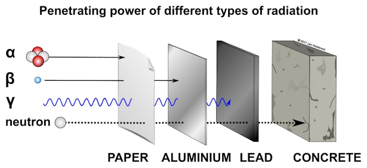
Penetration of Ionizing Radiation
For lots more information on ionizing radiation, check out Osha's website.
DFRobot
DFRobot is an awesome electronics company! From Geiger counters to LEDs, smart cameras to PH sensors, they have every electronic component you could ever want! I love all of their parts. Check them out here! Or:
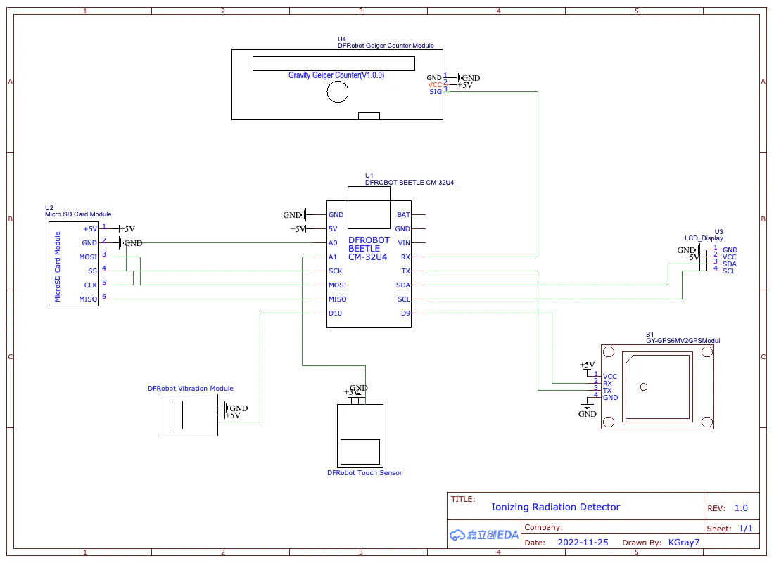
Wiring
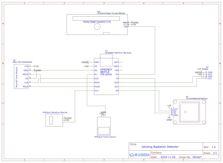
The wiring is fairly simple. Here is a description: (Schematic below)
Beetle - LCD:
5V - VCC
GND - GND
SCL - SCL
SDA - SDA
Beetle - SD Card:
5V - +5V
GND - GND
MOSI - MOSI
MISO - MISO
SCK - SCK
A0 - SS
Beetle - GPS:
5V - VCC
GND - GND
D9 - RX
D1 - TX
Beetle - Vibration:
5V - VCC
GND - GND
D11 - SIG
Beetle - Touch:
5V - VCC
GND - GND
A1 - OUT
Beetle - Geiger Module:
5V - VCC
GND - GND
D0 - SIG
Beetle - Battery:
BAT - +
GND - -
If this description doesn't make much sense (and I wouldn't blame you 😉), here is the schematic:
#include <DFRobot_RGBLCD1602.h>
#include <TinyGPS++.h>
#include <SoftwareSerial.h>
#include <SD.h>

#define geiger_pin 0
#define button A1
#define vibration 11
#define SDss A0

static const int RXPin = 9, TXPin = 1;//D1/D9
static const uint32_t GPSBaud = 9600;
First, include the needed libraries, set the pins, and set the GPS baud rate.
boolean vib = true;

int i = 0;
const int n = 0;
volatile long buf[n];
float timebetweenpulses = 0;
int pos = 0;

long lastmillis = 0;
long currentmillis = 0;
int looptimerlength = 30000;//30 sec

float lastReading = 0;
float lastUSVH = 0;
float CPM = 0;
float USVH = 0;

int mode = 1;

int timer1 = 0;
int count = 0;
int count2 = 0;

#define arrSize(X) sizeof(X) / sizeof(X[0])
Next we set up a lot of variables to store info.
float milli[] =            { 2000,     1000,       900,      800,        700,        600,      500,       400,          300,           100,       50     };
float values[] =           {   0,        1,         2,        5,          10,         40,      100,       250,          400,          1000,      10000   };
const char* equivalent[] = {"Normal", "Normal", "Airport", "Dental", "Norm(1day)", "Flight", "X-Ray", "NPP(1year)", "Mammogram",  "Gov Limit", "CT Scan" };
This part can be set to your liking. The milli values are time between readings in milliseconds, in comparison to uSvh values in the next line down. The equivalents are things that would produce the amount of radiation detected in comparison to the uSvh values.
File myFile;

DFRobot_RGBLCD1602 lcd(/*lcdCols*/16,/*lcdRows*/2);
TinyGPSPlus gps;
SoftwareSerial ss(RXPin, TXPin);
Here we create instances of the libraries that we used.
  pinMode(geiger_pin, INPUT);
  pinMode(vibration, OUTPUT);
  pinMode(SDss, OUTPUT);
  pinMode(button, INPUT);

  ss.begin(GPSBaud);
First in void setup(), we set the pin modes and the GPS baud rate.
  lcd.init();
  lcd.customSymbol(1,motor1Char);
  lcd.customSymbol(2,motor2Char);
  lcd.customSymbol(4,fullChar);

  lcd.setCursor(4,0);
  lcd.print(F("Geiger"));
  lcd.setCursor(3,1);
  lcd.print(F("Counter"));
  lcd.setRGB(0,255,0);
  delay(3000);
  for (int p=0;p<2;p++){
    for (int p=255;p>0;p--) {
      lcd.setRGB(0, p, 0);
      delay(3);
    }
    for (int p=0;p<255;p++) {
      lcd.setRGB(0, p, 0);
      delay(3);
    }
  }
  for (int i=0;i<15;i++){
    lcd.scrollDisplayRight();
    delay(100);
  }
Next, we start the screen, and run through a boot up sequence.
if (!SD.begin(SDss)) {
    lcd.clear();
    lcd.setRGB(255, 0, 0);
    lcd.setCursor(1,0);
    lcd.print(F("SD Init Failed"));
    delay(5000);
    lcd.clear();
  }

  myFile = SD.open("google.txt", FILE_WRITE);
  if (myFile){
    myFile.println(F("ID,Name,Date,Time,Latitude,Longitude,CPM,uSvh"));
    myFile.close();
  }
  else {
    Serial.println("Failed to open google file");
  }
  myFile = SD.open("googler.txt", FILE_WRITE);
  if (myFile){
    myFile.println(F("ID,Name,Date,Time,Latitude,Longitude,TimeBPulses"));
    myFile.close();
  }
  else {
    Serial.println("Failed to open google file");
  }
Here we start the SD card, and initiate the correct files.
attachInterrupt(digitalPinToInterrupt(geiger_pin), isrcount, FALLING);Lastly in voidloop(), we attach the geiger data pin to an interrupt, that way a pulse on the geiger pin will interrupt the code, and run a separate function called isrcount().
  while (ss.available() > 0){
    gps.encode(ss.read());
  }
First, now in voidloop(), we check the GPS serial and read it if it is available.
currentmillis = millis();Next we update the currentmillis variable to contain the current millisecond count since startup.
  if ((currentmillis - lastmillis) >= looptimerlength){
    CPM = pos*(60000/looptimerlength);
    USVH = (pos*(60000/looptimerlength))/153.80;
    Serial.print("CPM: ");
    Serial.println(CPM);
    Serial.print("uSv/h: ");
    Serial.println(USVH);
    lastUSVH = USVH;
    pos=0;
    lastmillis = millis();
    if (mode == 3){
      lcdDisplayData(3);
      lastUSVH = USVH;
      if (vib){
        if (USVH > 2){
          digitalWrite(vibration, HIGH);
          delay(300);
          digitalWrite(vibration, LOW);
        }
      }
    }
    saveToFile(1);
  }
Here, we compare the currentmillis with the lastmillis. Then, we check if this value is greater than the looptimerlength. If it is, we calculate the CPM and USVH, and display it to the serial monitor. At the bottom, we save the measurement data to the SD card.
  if (lastReading != timebetweenpulses){
    if (mode == 1){
      lcdDisplayData(1);
      lastReading = timebetweenpulses;
    }
    else if (mode == 2){
      lcdDisplayData(2);
      lastReading = timebetweenpulses;
    }
  }
Next, we check if the last reading and the current one are the same. If they are, then there's no need to update the display! If they aren't (i.e. the value is updated), then we check the mode and display the data correctly. finally, the lastReading is updated to the current one, as it is now old.
if (digitalRead(button) == HIGH){
    int taps = 0;
    redo:

    taps++;
    if (taps >= 6){
      taps = 1;
    }
    Serial.print("Taps: ");
    Serial.println(taps);

    while (digitalRead(button) == HIGH);

    do {
      timer1++;
      delay(1);
      if (timer1 > 2000){
        timer1 = 0;
        goto exi;
      }
    } while (digitalRead(button) == LOW);

    if (digitalRead(button) == HIGH){
      timer1 = 0;
      goto redo;
    }
    exi:
    Serial.print("Completed Taps: ");
    Serial.println(taps);

    lcd.clear();

    if (taps == 1){
      lcd.setRGB(0, 255, 0);
      lcd.setCursor(0,0);
      lcd.print(F("Standard Mode"));
      delay(3000);
      mode = 1;
    }
    else if (taps == 2){
      lcd.setRGB(0, 255, 255);
      lcd.setCursor(3,0);
      lcd.print(F("Bar Mode"));
      delay(3000);
      mode = 2
    }
    else if (taps == 3){
      lcd.setRGB(0, 0, 255);
      lcd.setCursor(0,0);
      lcd.print(F("Equivalents Mode"));
      delay(3000);
      lcd.clear();
      lcd.setRGB(0, 255, 0);
      lcd.setCursor(0,0);
      lcd.print(F("Acquiring Data"));
      mode = 3;
    }
    else if (taps == 4){
      vib = !vib;
      lcd.setRGB(255, 0, 255);
      lcd.setCursor(3,0);
      lcd.print(F("Vibration"));
      lcd.setCursor(4,1);
      lcd.print(vib > 0 ? "On" : "Off");
      for (int i=0;i<10;i++){
        lcd.setCursor(14,1);
        lcd.write(1);
        delay(300);
        lcd.setCursor(14,1);
        lcd.write(2);
        delay(300);
      }
      mode = 1;
    }
    else if (taps == 5){
      seconds = !seconds;
      lcd.setRGB(255, 0, 255);
      lcd.setCursor(3,0);
      lcd.print(F("Seconds"));
      lcd.setCursor(4,1);
      lcd.print(seconds > 0 ? "On" : "Off");
      delay(3000);
      lcd.clear();
      mode = 1;
    }
  }
}
This long if function is for reading the touch sensor and adjusting the modes / settings accordingly. The first three are modes, and the last two are settings; vibration on or off, and data displayed in seconds or milliseconds.
void isrcount() {
  i++;
  if (i>= 3){
    i=1;
  }

  buf[i] = millis();

  if (buf[1] <= buf[2]){
    timebetweenpulses = buf[2] - buf[1];
    Serial.print("Time between pulses: ");
    Serial.println(timebetweenpulses/1000);
    buf[1] = 1;
  }
  else if (buf[1] >= buf[2]){
    timebetweenpulses = buf[1] - buf[2];
    Serial.print("Time between pulses: ");
    Serial.println(timebetweenpulses/1000);
    buf[2] = 1;
  }
  pos++;

  if (timebetweenpulses < 500){
    saveToFile(2);
  }

  if (mode == 1 || mode == 2){
    if (vib){
      if (timebetweenpulses < 1000){
        digitalWrite(vibration, HIGH);
        delay(300);
        digitalWrite(vibration, LOW);
      }
    }
  }
}
This isrcount() function is the interrupt function. If the interrupt is triggered by the Geiger counter, it runs this function! Every time this function runs, the pos (pulse count) increases by one. Also, the millis() is saved to a variable, so it can be compared with the last pulse's millis. After subtracting the last millis from the current millis, you can calculate the time in milliseconds between the two readings. At the bottom, depending on the mode, vibration setting, and timebetweenpulses, the vibration motor buzzes for 0.3 seconds.
int nearestEqual(int x, bool sorted = true) {
  int idx = 0; // by default near first element
  int distance = abs(values[idx] - x);
  for (int i = 1; i < arrSize(values); i++) {
    int d = abs(values[i] - x);
    if (d < distance) {
      idx = i;
      distance = d;
    }
    else if (sorted) return idx;
  }
  return idx;
}
int nearestEqualMS(int x, bool sorted = true) {
  int idx = 0; // by default near first element
  int distance = abs(milli[idx] - x);
  for (int i = 1; i < arrSize(milli); i++) {
    int d = abs(milli[i] - x);
    if (d < distance) {
      idx = i;
      distance = d;
    }
    else if (sorted) return idx;
  }
  return idx;
}
These two similar functions calculate the "nearest equal" of the current value. The top one is for uSv/h measurements, and the bottom one is for milliseconds measurements (hence the nearestEqualMS).
void lcdDisplayData(int mo){
  lcd.clear();
  if (mo == 1){
    lcd.setCursor(0,0);
    lcd.print(F("Time in Pulses:"));
    lcd.setCursor(4,1);
    if (seconds){
      lcd.print(timebetweenpulses/1000);//seconds
    }
    else {
      lcd.print(timebetweenpulses);//milliseconds
    }
  }
  else if (mo == 2){
    lcd.setCursor(0,0);
    lcd.print(F("Time:"));
    lcd.setCursor(6,0);
    if (seconds){
      lcd.print(timebetweenpulses/1000);//seconds
    }
    else {
      lcd.print(timebetweenpulses);//milliseconds
    }
    lcd.setCursor(0,1);
    lcdBar(timebetweenpulses);
  }
  else if (mo == 3){
    lcd.setCursor(0,0);
    lcd.print(F("uSv/h:"));
    lcd.setCursor(7,0);
    lcd.print(USVH);
    lcd.setCursor(0,1);
    if (USVH == 0.00){
      lcd.print("Normal");
    }
    else {
      lcd.print(equivalent[nearestEqual(USVH)]);
      delay(500);
    }
  }
  lcdbacklight();
}
Here is where the LCD is controlled. According to the modes, different data is shown. Lastly, the backlight is adjusted by using our lcdbacklight()function.
void lcdBar(int re){
  int inp = map(nearestEqualMS(re),0,9,0,14);
  for (int i=0;i<(inp+1);i++){
    lcd.setCursor(i+1,1);
    lcd.write(4);
  }
}
The bar function is surprisingly simple 😉. First we map the nearest equal of the current value to fill the display. Then, using a for loop, we draw the fullChar on the screen as many times as according to the inp value.
void lcdbacklight(){
  int theNearestEqual;
  if (mode == 1 || mode == 2){
    theNearestEqual = nearestEqualMS(timebetweenpulses);
  }
  else {
    theNearestEqual = nearestEqual(CPM);
  }
  switch (theNearestEqual) {
  case 0 :
    lcd.setRGB(0,255,0);
    break;
  case 1 :
    lcd.setRGB(0,255,0);
    break;
  case 2 :
    lcd.setRGB(0,255,0);
    break;
  case 3 :
    lcd.setRGB(150,255,0);
    break;
  case 4 :
    lcd.setRGB(255,255,0);
    break;
  case 5 :
    lcd.setRGB(255,180,0);
    break;
  case 6 :
    lcd.setRGB(255,100,0);
    break;
  case 7 :
    lcd.setRGB(255,0,0);
    break;
  case 8 :
    lcd.setRGB(255,0,150);
    break;
  case 9 :
    lcd.setRGB(175,0,255);
    break;
  default :
    break;
  }
}
This lcdbacklight function... well, does what it sounds like! It controls the backlight color according to the value by using a switchcase loop.
void saveToFile(int typ){
  if (typ != 0){
    count++;
    Serial.print("Count: ");
    Serial.println(count);
    if (typ == 1){
      myFile = SD.open("google.txt", FILE_WRITE);
    }
    else if (typ == 2){
      myFile = SD.open("googler.txt", FILE_WRITE);
    }

    if (myFile){
      myFile.print(count);
      myFile.print(",Geiger");
      myFile.print(count);
      myFile.print(",");
      myFile.print(gps.date.month());
      myFile.print(F("/"));
      myFile.print(gps.date.day());
      myFile.print(F("/"));
      myFile.print(gps.date.year());
      myFile.print(",");
      myFile.print(gps.time.hour());
      myFile.print(F(":"));
      myFile.print(gps.time.minute());
      myFile.print(F(":"));
      myFile.print(gps.time.second());
      myFile.print(",");
      myFile.print(gps.location.lat(),8);
      myFile.print(",");
      myFile.print(gps.location.lng(),8);
      myFile.print(",");
      if (typ == 1){
        myFile.print(CPM,2);
        myFile.print(",");
        myFile.println(USVH,2);
      }
      else if (typ == 2){
        myFile.println(timebetweenpulses,3);
      }
      myFile.close();
    }
    else {
      Serial.println("Failed to write");
    }
  }
}
The last function finally! Phew. This function is for saving all the data to the SD card. I designed the way the data was saved for it to be able to easily be added to a chart, or Google Earth. Here is an example of what the data would look like:
ID, Name, Date, Time, Latitude, Longitude, CPM, uSvh
1, Geiger1, 11/25/2022, 20:35:54, 41.09264839, -52.016593827, 8.00, 0.05
The top part is the header that is printed in the voidsetup(). The bottom part is a sample of what the data would look like.
For steps on how to program the device, check out the GitHub repository!
https://github.com/Kgray44/Ionizing-Radiation-Detector
Or, go here!
How To Use The Device
To use the device, it first must be put together and programmed 😉.
When the device first powers on, you will see a display as below:
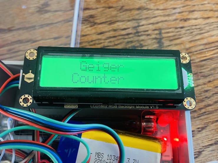
Start Screen
If the SD card is not inserted, not formatted correctly, or not wired correctly, the LCD screen will display this:
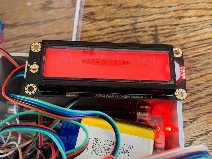
SD Init Failed
After first starting up, the mode will be set to mode 1. There are three modes; Standard Mode (mode 1), Bar Mode (mode 2), and Equivalents Mode (mode 3).
The Standard Mode looks like below:
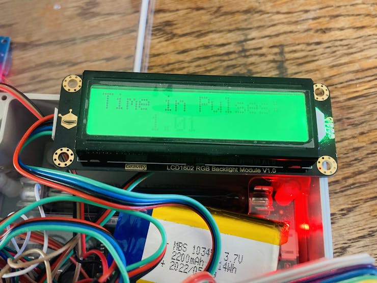
Time in Pulses: 1.01
This mode displays the time between pulses on the second row.
Bar Mode looks like below:
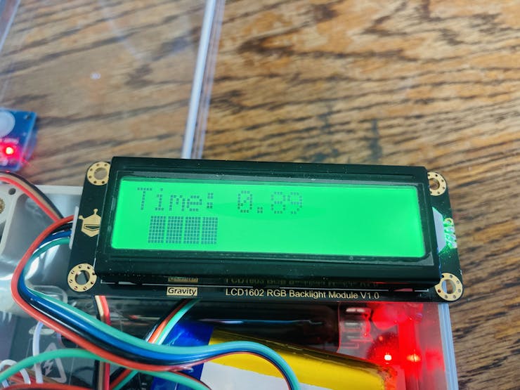
Time: 0.89 (4 bars)
This mode displays time between pulses on the top row. On the second row, the bar is displayed.
The Equivalents Mode looks like this:
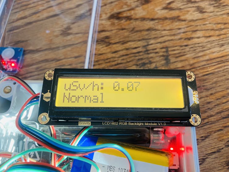
uSvh/h: 0.07
This mode can take up to 30 seconds after pressing the button. During that time, this screen will be displayed:
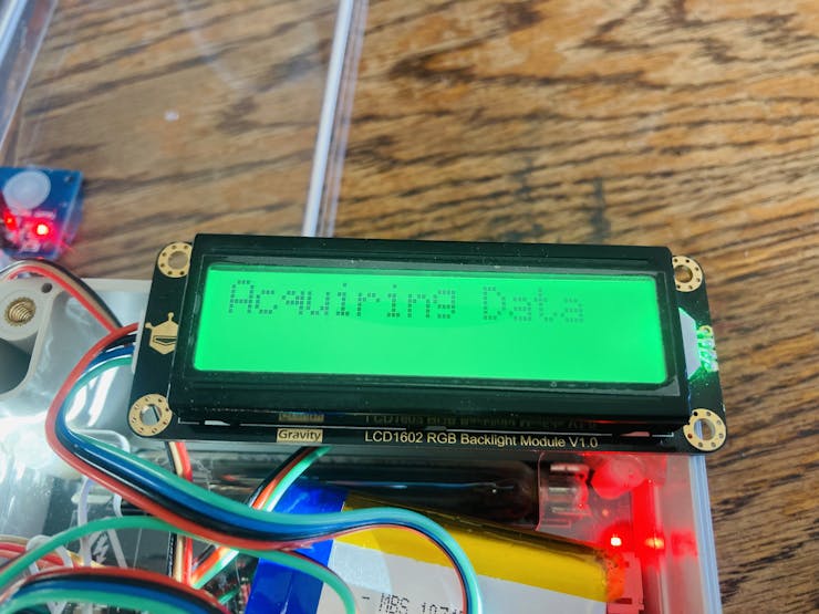
Acquiring Data display
This mode updates once every 30 seconds. It works by counting the pulses that are read in 30 seconds, and then is multiplied by 2 to get CPM (Counts Per Minute). The CPM value is divided by 153.80 to get the uSv/h value (this calculation can be different for different geiger-muller bulbs).
In this mode, the measurement in uSv/h (micro-Sieverts per hour) is displayed on the top row. The bottom row displays the equivalent device that would emit the amount of radiation measured.
How to Change the Mode
To change the mode, you tap the touch sensor. Here is a tap map:
One tap sets it to mode 1 (standard)Two taps sets it to mode 2 (bar)Three taps sets it to mode 3 (equivalents)Four taps sets the vibration motor either on or off according to the last setting (default is on)Five taps sets the time between pulses either to being displayed in seconds or milliseconds, depending on the last setting (default is seconds)
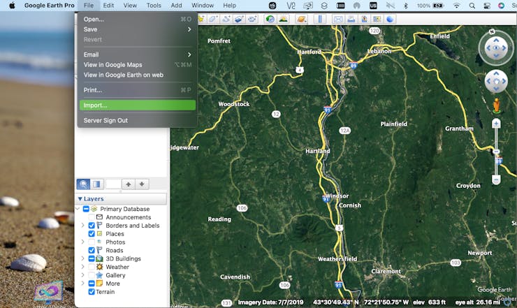
How to Add Data to Google Earth
To add the data file to Google Earth, open Google Earth and click on File / Import.
A screen will pop up that requests you to select the file that you would like to import.
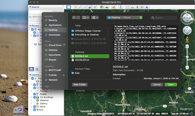
"GOOGLE.TXT" is the standard data file that has saved data readings with CPM and uSv/h every 30 seconds. "GOOGLER.TXT" is data that is saved every time the Seconds between readings drops below 500ms.
To get the data from the device, remove the SD card and plug it into your PC. Transfer the files to your computer, and then you can select them as shown above.
Next, a screen pops up that is for the settings. Make sure to select "Delimited" and "Comma".
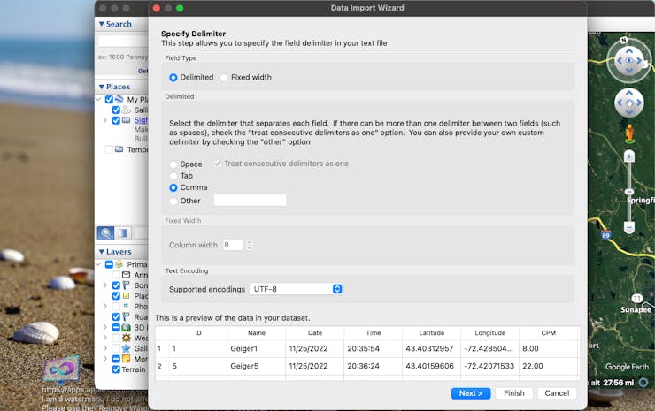
Click "Next >", and a screen will pop up that asks which columns are latitude and longitude. Select "Latitude" and "Longitude".
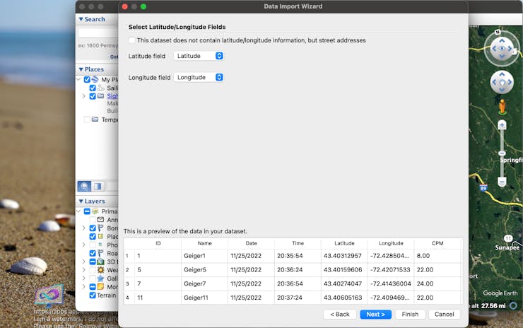
Click "Next >" again, and a screen will come up that asks for each column's data type. In order, it should be:
• Integer• String• String• String• Floating Point• Floating Point• Floating Point• Floating Point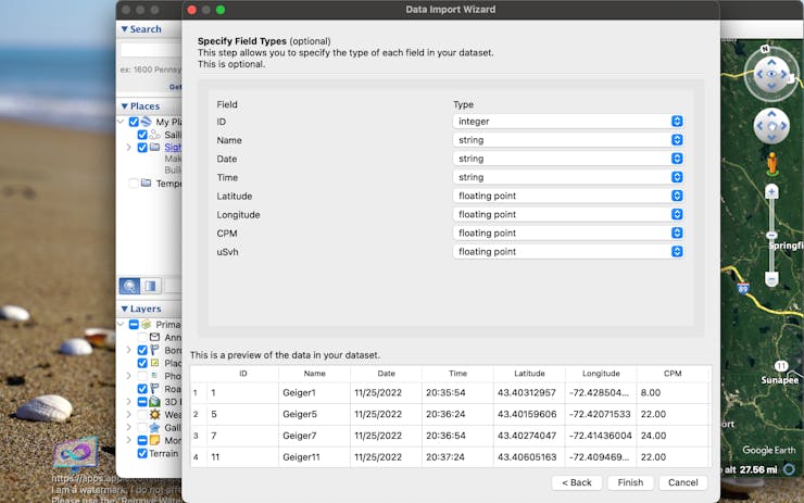
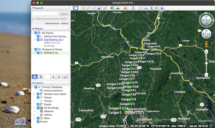
Click "Finish", and all the data points will show on the map!
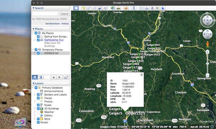
Now, if you click on one of the data points, it will give you all of the info for that point.
How to Add Data to Numbers (MacOS)
To add the device's data to a Numbers chart, just change the file from "GOOGLE.TXT" to "GOOGLE.CSV". That's all! Now, when you open the file, it will open in Numbers automatically.
SlideShow
I made a slideshow of me putting it together!
Wrapping Up
If you have any questions or thoughts, feel free to post in the comments!
Also, if you would like me to build this project for you, email me at
Check out more of my awesome projects here!
Schematics
Schematic
Code
geiger.ino
C/C++
#include <DFRobot_RGBLCD1602.h>
#include <TinyGPS++.h>
#include <SoftwareSerial.h>
#include <SD.h>

#define geiger_pin 0
#define button A1
#define vibration 11
#define SDss A0

static const int RXPin = 9, TXPin = 1;//D1/D9
static const uint32_t GPSBaud = 9600;

const byte motor1Char[8] = {
  0b00110,
  0b00110,
  0b00100,
  0b01110,
  0b01110,
  0b01110,
  0b01110,
  0b01110
};

const byte motor2Char[8] = {
  0b01100,
  0b01100,
  0b00100,
  0b01110,
  0b01110,
  0b01110,
  0b01110,
  0b01110
};

const byte fullChar[8] = {
  0b11111,
  0b11111,
  0b11111,
  0b11111,
  0b11111,
  0b11111,
  0b11111,
  0b11111
};

boolean vib = true;
boolean seconds = true;

int i = 0;
const int n = 0;
volatile long buf[n];
float timebetweenpulses = 0;
int pos = 0;

long lastmillis = 0;
long currentmillis = 0;
int looptimerlength = 30000;//30 sec

float lastReading = 0;
float lastUSVH = 0;
float CPM = 0;
float USVH = 0;

int mode = 1;

int timer1 = 0;
int count = 0;
int count2 = 0;

#define arrSize(X) sizeof(X) / sizeof(X[0])

float milli[] =            { 2000,     1000,       900,      800,        700,        600,      500,       400,          300,           100,       50     };
float values[] =           {   0,        1,         2,        5,          10,         40,      100,       250,          400,          1000,      10000   };
const char* equivalent[] = {"Normal", "Normal", "Airport", "Dental", "Norm(1day)", "Flight", "X-Ray", "NPP(1year)", "Mammogram",  "Gov Limit", "CT Scan" };

File myFile;

DFRobot_RGBLCD1602 lcd(/*lcdCols*/16,/*lcdRows*/2);
TinyGPSPlus gps;
SoftwareSerial ss(RXPin, TXPin);

void setup() {
  pinMode(geiger_pin, INPUT);
  pinMode(vibration, OUTPUT);
  pinMode(SDss, OUTPUT);
  pinMode(button, INPUT);
  digitalWrite(vibration, LOW);

  ss.begin(GPSBaud);

  lcd.init();
  lcd.customSymbol(1,motor1Char);
  lcd.customSymbol(2,motor2Char);
  lcd.customSymbol(4,fullChar);

  lcd.setCursor(4,0);
  lcd.print(F("Geiger"));
  lcd.setCursor(3,1);
  lcd.print(F("Counter"));
  lcd.setRGB(0,255,0);
  delay(3000);
  for (int p=0;p<2;p++){
    for (int p=255;p>0;p--) {
      lcd.setRGB(0, p, 0);
      delay(3);
    }
    for (int p=0;p<255;p++) {
      lcd.setRGB(0, p, 0);
      delay(3);
    }
  }
  for (int i=0;i<15;i++){
    lcd.scrollDisplayRight();
    delay(100);
  }


  if (!SD.begin(SDss)) {
    lcd.clear();
    lcd.setRGB(255, 0, 0);
    lcd.setCursor(1,0);
    lcd.print(F("SD Init Failed"));
    delay(5000);
    lcd.clear();
  }

  myFile = SD.open("google.txt", FILE_WRITE);
  if (myFile){
    myFile.println(F("ID,Name,Date,Time,Latitude,Longitude,CPM,uSvh"));
    myFile.close();
  }
  else {
    Serial.println("Failed to open google file");
  }
  myFile = SD.open("googler.txt", FILE_WRITE);
  if (myFile){
    myFile.println(F("ID,Name,Date,Time,Latitude,Longitude,TimeBPulses"));
    myFile.close();
  }
  else {
    Serial.println("Failed to open googler file");
  }

  attachInterrupt(digitalPinToInterrupt(geiger_pin), isrcount, FALLING);

}

void loop() {
  while (ss.available() > 0){
    gps.encode(ss.read());
  }

  if (gps.location.isUpdated()){
    Serial.print("Latitude: ");
    Serial.println(gps.location.lat(),6);
    Serial.print("Longitude: ");
    Serial.println(gps.location.lng(),6);
  }

  currentmillis = millis();
  if ((currentmillis - lastmillis) >= looptimerlength){
    CPM = pos*(60000/looptimerlength);
    USVH = (pos*(60000/looptimerlength))/153.80;
    Serial.print("CPM: ");
    Serial.println(CPM);
    Serial.print("uSv/h: ");
    Serial.println(USVH);
    lastUSVH = USVH;
    pos=0;
    lastmillis = millis();
    if (mode == 3){
      lcdDisplayData(3);
      if (vib){
        if (USVH > 2){
          digitalWrite(vibration, HIGH);
          delay(300);
          digitalWrite(vibration, LOW);
        }
      }
    }
    saveToFile(1);
  }

  if (lastReading != timebetweenpulses){
    if (mode == 1){
      lcdDisplayData(1);
      lastReading = timebetweenpulses;
    }
    else if (mode == 2){
      lcdDisplayData(2);
      lastReading = timebetweenpulses;
    }
  }

  if (digitalRead(button) == HIGH){
    int taps = 0;
    redo:

    taps++;
    if (taps >= 6){
      taps = 1;
    }
    Serial.print("Taps: ");
    Serial.println(taps);

    while (digitalRead(button) == HIGH);

    do {
      timer1++;
      delay(1);
      if (timer1 > 2000){
        timer1 = 0;
        goto exi;
      }
    } while (digitalRead(button) == LOW);

    if (digitalRead(button) == HIGH){
      timer1 = 0;
      goto redo;
    }
    exi:
    Serial.print("Completed Taps: ");
    Serial.println(taps);

    lcd.clear();

    if (taps == 1){
      lcd.setRGB(0, 255, 0);
      lcd.setCursor(0,0);
      lcd.print(F("Standard Mode"));
      delay(3000);
      mode = 1;
    }
    else if (taps == 2){
      lcd.setRGB(0, 255, 255);
      lcd.setCursor(3,0);
      lcd.print(F("Bar Mode"));
      delay(3000);
      mode = 2;
    }
    else if (taps == 3){
      lcd.setRGB(0, 0, 255);
      lcd.setCursor(0,0);
      lcd.print(F("Equivalents Mode"));
      delay(3000);
      lcd.clear();
      lcd.setRGB(0, 255, 0);
      lcd.setCursor(0,0);
      lcd.print(F("Acquiring Data"));
      mode = 3;
    }
    else if (taps == 4){
      vib = !vib;
      lcd.setRGB(255, 0, 255);
      lcd.setCursor(3,0);
      lcd.print(F("Vibration"));
      lcd.setCursor(4,1);
      lcd.print(vib > 0 ? "On" : "Off");
      for (int i=0;i<10;i++){
        lcd.setCursor(14,1);
        lcd.write(1);
        delay(300);
        lcd.setCursor(14,1);
        lcd.write(2);
        delay(300);
      }
      mode = 1;
    }
    else if (taps == 5){
      seconds = !seconds;
      lcd.setRGB(255, 0, 255);
      lcd.setCursor(3,0);
      lcd.print(F("Seconds"));
      lcd.setCursor(4,1);
      lcd.print(seconds > 0 ? "On" : "Off");
      delay(3000);
      lcd.clear();
      mode = 1;
    }
  }
}

void isrcount() {
  i++;
  if (i>= 3){
    i=1;
  }

  buf[i] = millis();

  if (buf[1] <= buf[2]){
    timebetweenpulses = buf[2] - buf[1];
    Serial.print("Time between pulses: ");
    Serial.println(timebetweenpulses/1000);
    buf[1] = 1;
  }
  else if (buf[1] >= buf[2]){
    timebetweenpulses = buf[1] - buf[2];
    Serial.print("Time between pulses: ");
    Serial.println(timebetweenpulses/1000);
    buf[2] = 1;
  }
  pos++;

  if (timebetweenpulses < 500){
    saveToFile(2);
  }

  if (mode == 1 || mode == 2){
    Serial.println("Mode check");
    if (vib){
      Serial.println("Vib true");
      if (timebetweenpulses < 1000){
        Serial.println("Vibration motor on");
        digitalWrite(vibration, HIGH);
        delay(300);
        digitalWrite(vibration, LOW);
      }
    }
  }
}

int nearestEqual(int x, bool sorted = true) {
  int idx = 0; // by default near first element
  int distance = abs(values[idx] - x);
  for (int i = 1; i < arrSize(values); i++) {
    int d = abs(values[i] - x);
    if (d < distance) {
      idx = i;
      distance = d;
    }
    else if (sorted) return idx;
  }
  return idx;
}
int nearestEqualMS(int x, bool sorted = true) {
  int idx = 0; // by default near first element
  int distance = abs(milli[idx] - x);
  for (int i = 1; i < arrSize(milli); i++) {
    int d = abs(milli[i] - x);
    if (d < distance) {
      idx = i;
      distance = d;
    }
    else if (sorted) return idx;
  }
  return idx;
}

void lcdDisplayData(int mo){
  lcd.clear();
  if (mo == 1){
    lcd.setCursor(0,0);
    lcd.print(F("Time in Pulses:"));
    lcd.setCursor(4,1);
    if (seconds){
      lcd.print(timebetweenpulses/1000);//seconds
    }
    else {
      lcd.print(timebetweenpulses);//milliseconds
    }
  }
  else if (mo == 2){
    lcd.setCursor(0,0);
    lcd.print(F("Time:"));
    lcd.setCursor(6,0);
    if (seconds){
      lcd.print(timebetweenpulses/1000);//seconds
    }
    else {
      lcd.print(timebetweenpulses);//milliseconds
    }
    lcd.setCursor(0,1);
    lcdBar(timebetweenpulses);
  }
  else if (mo == 3){
    lcd.setCursor(0,0);
    lcd.print(F("uSv/h:"));
    lcd.setCursor(7,0);
    lcd.print(USVH);
    lcd.setCursor(0,1);
    if (USVH == 0.00){
      lcd.print("Normal");
    }
    else {
      lcd.print(equivalent[nearestEqual(USVH)]);
      delay(500);
    }
  }
  lcdbacklight();
}

void lcdBar(int re){
  int inp = map(nearestEqualMS(re),0,9,0,14);
  for (int i=0;i<(inp+1);i++){
    lcd.setCursor(i+1,1);
    lcd.write(4);
  }
}

void lcdbacklight(){
  int theNearestEqual;
  if (mode == 1 || mode == 2){
    theNearestEqual = nearestEqualMS(timebetweenpulses);
  }
  else {
    theNearestEqual = nearestEqual(CPM);
  }
  switch (theNearestEqual) {
  case 0 :
    lcd.setRGB(0,255,0);
    break;
  case 1 :
    lcd.setRGB(0,255,0);
    break;
  case 2 :
    lcd.setRGB(0,255,0);
    break;
  case 3 :
    lcd.setRGB(150,255,0);
    break;
  case 4 :
    lcd.setRGB(255,255,0);
    break;
  case 5 :
    lcd.setRGB(255,180,0);
    break;
  case 6 :
    lcd.setRGB(255,100,0);
    break;
  case 7 :
    lcd.setRGB(255,0,0);
    break;
  case 8 :
    lcd.setRGB(255,0,150);
    break;
  case 9 :
    lcd.setRGB(175,0,255);
    break;
  default :
    break;
  }
}

void saveToFile(int typ){
  if (typ != 0){
    count++;
    Serial.print("Count: ");
    Serial.println(count);
    if (typ == 1){
      myFile = SD.open("google.txt", FILE_WRITE);
    }
    else if (typ == 2){
      myFile = SD.open("googler.txt", FILE_WRITE);
    }

    if (myFile){
      myFile.print(count);
      myFile.print(",Geiger");
      myFile.print(count);
      myFile.print(",");
      myFile.print(gps.date.month());
      myFile.print(F("/"));
      myFile.print(gps.date.day());
      myFile.print(F("/"));
      myFile.print(gps.date.year());
      myFile.print(",");
      myFile.print(gps.time.hour());
      myFile.print(F(":"));
      myFile.print(gps.time.minute());
      myFile.print(F(":"));
      myFile.print(gps.time.second());
      myFile.print(",");
      myFile.print(gps.location.lat(),8);
      myFile.print(",");
      myFile.print(gps.location.lng(),8);
      myFile.print(",");
      if (typ == 1){
        myFile.print(CPM,2);
        myFile.print(",");
        myFile.println(USVH,2);
      }
      else if (typ == 2){
        myFile.println(timebetweenpulses,3);
      }
      myFile.close();
    }
    else {
      Serial.println("Failed to write");
    }
  }
}
Ionizing Radiation Detector Github
Github Repository for the code.
Kgray44 / Ionizing-Radiation-Detector
This code is for building an Ionizing Radiation Detector using Arduino! — Read More
https://www.hackster.io/k-gray/ionizing-radiation-detector-a0a782
Latest commit to the master branch on 11-28-2022