

This project is for building a live sailboat tracking system that communicates over LoRa with E22-900M30S modules!

The Story
Hello 👋!
I just bought a sailboat this spring, and was having so much fun on it! Other people accompany me on these trips; some on the boat, and some on shore. I thought it would be fun for the people on shore to see how fast I am moving, in which direction, how far I am heeling over, etc. So, I made a whole project to do just that!
DFRobot
DFRobot sponsored many parts for this project. Their modules and electronic components are amazing! They design and build various parts, from accelerometers like the one I used in this project, to smart cameras (husky lens)! They have every electronics part you would ever need on their website, found here: dfrobot.com .
JLCPCB
JLCPCB sponsored the PCBs for this project! I order all of my PCBs from them and they turn out amazing every time! All of the PCBs I have received are high quality with no defects; shipping and production is fast; you can't beat the price; and customer service is extremely helpful. Order your PCBs today at JLCPCB.com.
How It Works
First off, I had to think of a good way for communication; I had to get the data from my sailboat, to a smartphone on land. Many places I go sailing, don't have any cellular signal, so cellular modules wouldn't work. I still want long distances though, so what else besides LoRa (it stands for Long Range radio)! iPhones communicate via WiFi, Bluetooth, or cellular; not radio. So, I decided on a perfect setup as pictured below:
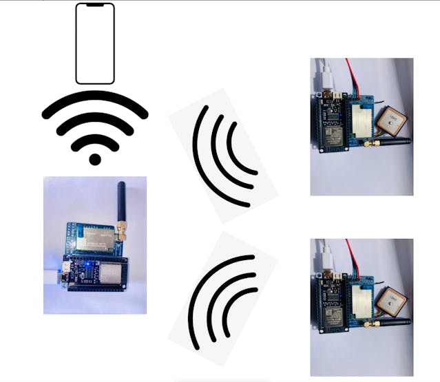
Sailboat Monitoring Connection Diagram
Both of the right nodes, collect and send all of the GPS data and accelerometer data to the base station on the left, which relays the info to a webpage that it hosts on its own network.
To use it on your phone, you connect to the WiFi network "Sailboat Monitoring", then go to your favorite browser and type in "192.168.4.1" (the base station's IP address). A webpage pops up with all of the data from both nodes on it!
Its Uses
This project is such a simple concept, it has many uses!
It is perfect for making sure sailors are safe, and not in danger. By monitoring heeling angle, you can tell if the sailor has capsized. By knowing the coordinates, you are able to quickly start a rescue. By checking the Top Speed, you can see who was the fastest 😉. By keeping an eye on the course, you can warn the sailor of objects or landmasses in his path. This setup is also good for sailboat monitoring in regattas and races!
Apart from boat related uses, this technological idea can be used for relatively close proximity tracking and monitoring of people and their safety. This is helpful to prevent getting lost during hiking, for example.
From farmers in the wheat fields of Kansas, to lobster fishermen in the trawlers off the coast of Maine, to bikers in the Mojave desert of the American West, to hang-gliders in the air off the cliffs of Yosemite National Park, this technological concept can keep everyone safe.
Health, safety, and productivity is a large concern for business owners, small and large. When participating in outdoor activities, the safety and well-being of all, is catamount. Therefore, this project aims to promote the well being of all people who enjoy outdoor activities, of any age. From the 8yo who likes to bike to school, to the 40yo who drives a tractor in a wheat field, this concept will make sure of their safety in the process.
Connections (Wiring)
To make the wiring easier and more permanent, I created a Fire-Beetle E22 LoRa Shield. You can find my PCB (Gerber) file at the bottom of this tutorial, along with the schematic. Please note that there are some issues with this design though.
_china_us_competition_2_2022-06-29_QtfwRTj4Sk.png?auto=compress%2Cformat&w=740&h=555&fit=max)
In essence, my design consists of:
• a battery charger
• a 5V booster for the Fire-Beetle and the LoRa module• a 12V booster for wind direction and wind speed sensors• pin headers for those two sensors along with GPS, and an accelerometer• and an exterior antenna connector.The LoRa to FireBeetle connections (shown in the schematic) are:
LoRa - FireBeetle
- RXEN D2- TXEN D3- NSS D4- NRST D9- BUSY A4- SCK SCK- MOSI MOSI- MISO MISO- *DIO1 IO4*Pin that needs to be connected, but is not in the schematic.
The FireBeetle pins crossed out with green "x"s on the schematic, are the pins used for the DFRobot FireBeetle HT1632C Display shield. I did not incorporate this part into my project, but feel free to change or add whatever you like!
My Schematic Design Issues:
• The battery charger is always trying to charge, instead of only when a USB cable is attached to the FireBeetle, due to 5V booster looping. Instead, I attached the battery to the FireBeetle battery port, and did not use my builtin battery charger. Please note if you try this workaround, a wire must be connected from the battery + pin to the battery + pin on my LoRa Shield, and the battery charging IC (SD8065) desoldered.• windDirRX, windDirTX, GPS_RX, and GPS_TX are connected to the wrong FireBeetle pins; use of these pins disrupts the ESP32 when running. I instead wired GPS_RX and GPS_TX to IO14 and IO12, and I did not use the wind sensors.• DIO1 needs to be wired to an available FireBeetle IO pin. I wired it to IO4.• A filtering capacitor must be added as close as possible to the LoRa module power pins. I used a 47µF capacitor.Putting Everything Together
To make this project as permanent as possible, I decided to put everything into a waterproof project enclosure I found on amazon.
I used my soldering iron to create a hole for the antenna, and a hole for a power switch I decided to add.
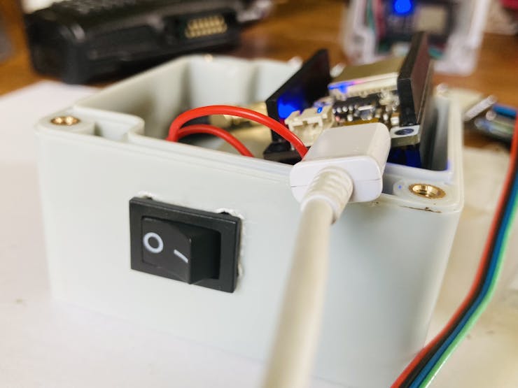
Power Switch
To put everything into the case, I first attached the battery to the FireBeetle, then set it in the bottom. Next went the FireBeetle, already inserted into the 12KM LoRa shield I designed. Lastly (for the transmitters), I hot glued the accelerometer to the wall of the enclosure, to keep it steady, and placed the gps module / antenna on top of the radio module.
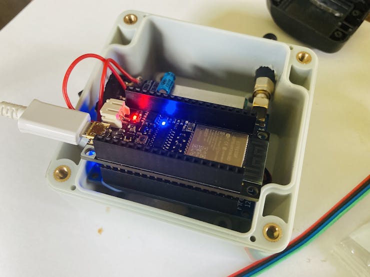
Everything was a tight fit, but I managed to squeeze it in there. I did place some thin packing material foam between the battery and the rest of the parts, to prevent the battery being punctured.
Adding Fire-Beetle to the Arduino IDE
A quick note: the FireBeetle I used is the "FireBeetle ESP32", not the newer "FireBeetle ESP32-E".
First, open your Arduino IDE and go to Arduino / Preferences.
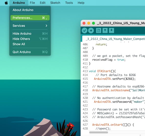
Then click on the window icon next to Additional Boards Manager URLs.
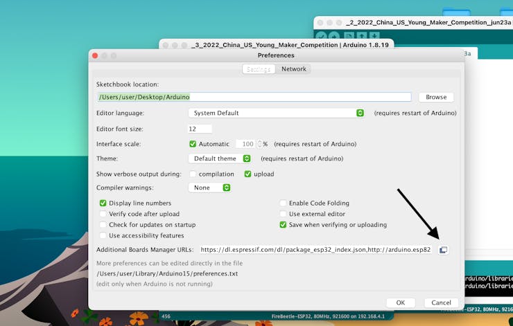
Next, copy and paste this link (https://dl.espressif.com/dl/package_esp32_index.json) into the window that pops up.
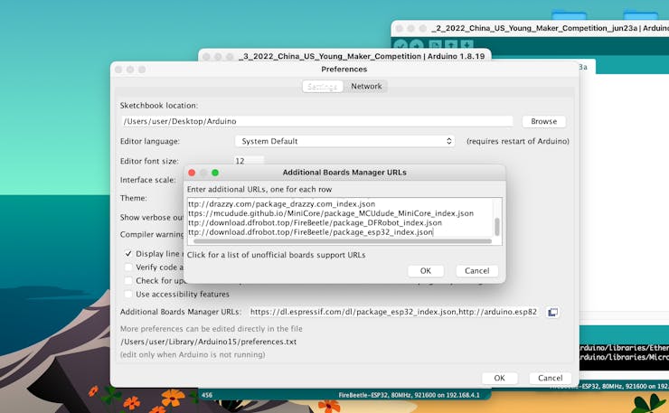
Now click the OK button on both windows.
Next, go to Tools / Boards / Board Manager.
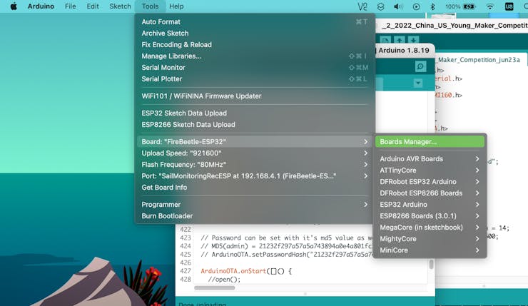
Then search for "ESP32"; a "esp32" board addition should show up. Click on the newest version and click install.
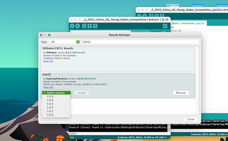
That's it! Now, if you go to Tools / Board you should find a ESP32 folder, in which will be a "FireBeetle ESP32" board option. Select this as the board type for programming.
Code
To upload my code (found on GitHub:https://github.com/Kgray44/Sailboat-Monitoring-over-LoRa), first you must program the SPIFFS.
First, download my code found on Github, and add it to your IDE as explained in the Readme.md file in the repository.
Next, open the receiver sketch by going to File / Sketchbook / Sailboat_Monitoring_Receiver.ino, and the transmitter sketch by going to File / Sketchbook / Sailboat_Monitoring_Transmitter.ino.
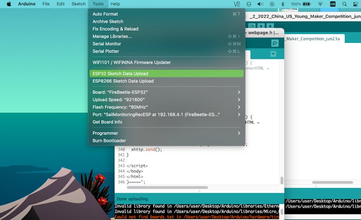
Because my project uses SPIFFS to store several png icons, they need to be added first on the receiver. Click on Tools / ESP32 Sketch Data Upload. This will program the png files found in the sketch's data folder to the ESP32's SPIFFS. If you would like to learn more about what SPIFFS is and how it works, check out this awesome website: https://randomnerdtutorials.com/esp32-web-server-spiffs-spi-flash-file-system
Next, you can upload the code by pressing the Upload button found on the sketch.
For the transmitter, I have set up the code so that it works for 2 transmitter nodes. The current node you are programming can be set at the top of the transmitter sketch with the variable nodenumber. So, set that variable to 0 when programming the first node, and set it to 1 for programming the second node.
Once you have correctly set that variable, upload the code to your transmitter(s), and thats all!
How to Use it
Once you have correctly programmed your receiver and transmitter(s), you are ready to try it out!
First, power up your receiver and transmitter(s).
Then go to WiFi, under settings on your smartphone, and connect to the network Sailboat Monitoring. The password is iLoveSailing! (so fitting, I know).
Now, open a new Safari tab and type "192.168.4.1" as the URL. A webpage will appear with all of your data on it! All the data is live and it updates automatically periodically.
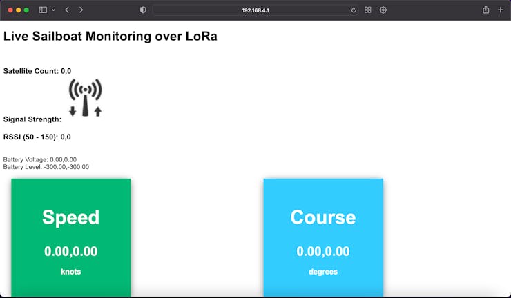
At the top of the webpage, is the satellite count for both the transmitting nodes.
Next is the signal strength icon; 5 bars through 0 bars.
Then the RSSI for both the transmitters.
There is battery voltage and level things, but they are not working at the time of this writing.
Then, there is Speed, Course, Top Speed, Altitude, Heeling Angle, Rolling Angle, Latitude, Longitude, and a Map.
When you click on the bottom map link, it will bring you to a new page. Read and follow the directions, and you will be able to see the exact position of one of the nodes! Please note that this is not live though, and you will have to go back to the main webpage to refresh it.
Wrapping Up
That was it for this tutorial! If you have any questions or comments, please post in the comment section below, and give this a thumbs up if you enjoyed it!
Instructables link: https://www.instructables.com/Live-Sailboat-Monitoring-Over-LoRa/
Hackster link: https://www.hackster.io/k-gray/live-sailboat-monitoring-over-lora-7fc8a4
Github link: https://github.com/Kgray44/Sailboat-Monitoring-over-LoRa
Hackaday link: https://hackaday.io/project/186147-live-sailboat-monitoring-over-lora
Check out my other tutorials:


