
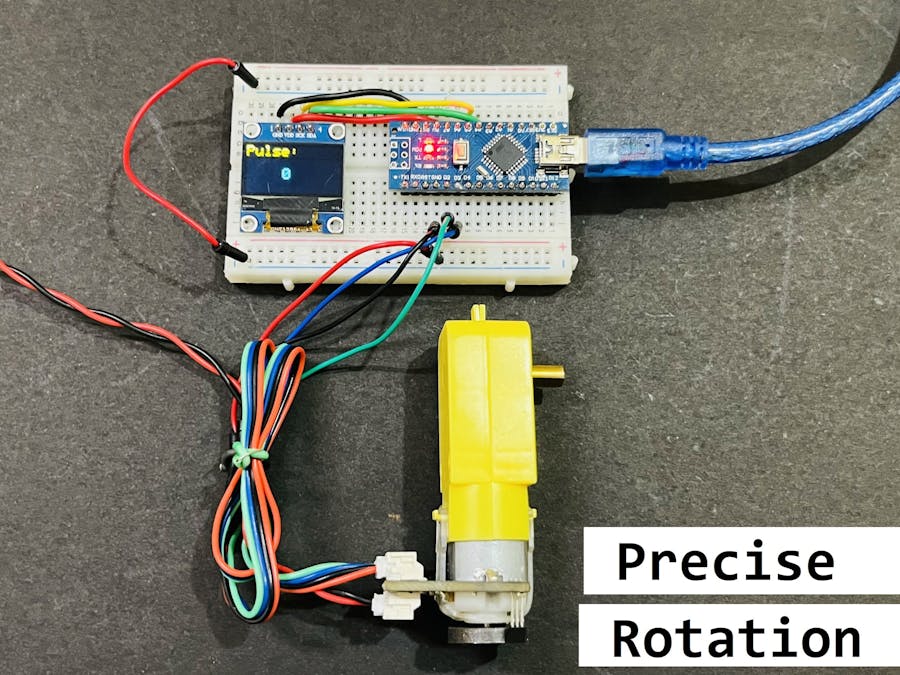
To precisely control the BO motor or to make any low cost project using PID we can consider this types of encoder integration with motors.
Things used in this project
Software apps and online services
Hand tools and fabrication machines
- Soldering iron (generic)
- Solder Wire, Lead Free
Story
Geared Dc motors are used in a lot of hobby projects like in making some kind of robot car and moving robotics. But for precise movement it is very important to use special kind of motors. For example for a balancing robot, we have to use stepper motors (proper stepping of wheel). Because in balancing the movement needed is very precise and normal motor can not complete the task. But there is one solution to these problems where we do not want to use stepper motors but want precise movement then encoder can be used with BO motors.
This encoder just record the rotation speed and direction and convert them into a pulses which can be paired with a microcontroller and driver to precisely change the voltage levels according to the desired pulses needed. These pulse control finally decide the movement speed of motor and using BO motors is very cost effective solution.
How magnetic encoder works:
An electronic magnetic rotary encoder utilizes magnetic fields to measure the rotation of an object. It consists of a magnetized rotor and a stationary sensor. As the rotor rotates, the sensor detects changes in the magnetic field and converts them into electrical signals.
These signals are processed to determine the rotational position, speed, and direction of the object. The sensor can be based on various technologies, such as Hall effect sensors or magneto resistive sensors, which detect the magnetic field variations. By analyzing these signals, the encoder provides accurate rotational data, making it useful for applications such as motor control, robotics, and industrial automation.
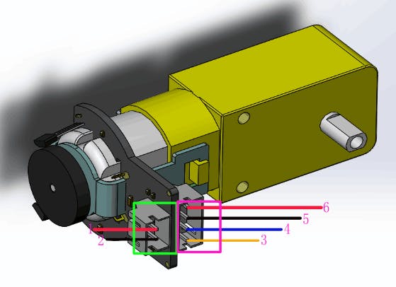
A simple encoder consists of 4 wires (2 for power and 1 for interrupt and other 1 for rotation direction). Microcontroller never checks for any motion recorded by encoder, but encoder by itself by generating an interrupt tells the microcontroller and the step is recorded.
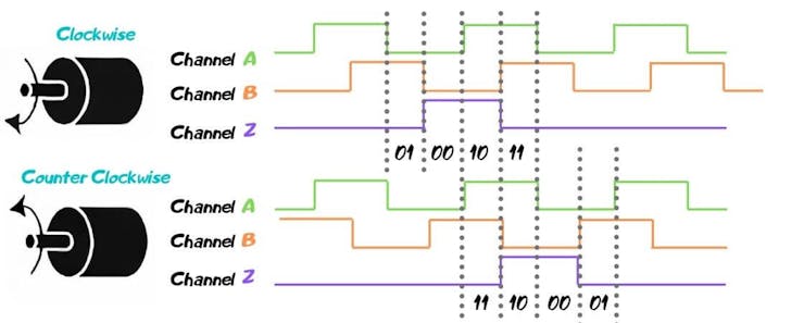
Encoder A (labelled C1, PinA) of the motor connects to pin 2 of the Arduino. Pin 2 of the Arduino will record every time there is a rising digital signal from Encoder A.
Encoder B (labelled C2, PinB) of the motor connects to pin 3 of the Arduino. The signal that is read off pin 3 on the Arduino will determine if the motor is moving forward or in reverse.
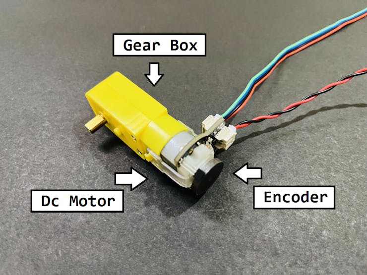
Gear motor and Encoder Specs:
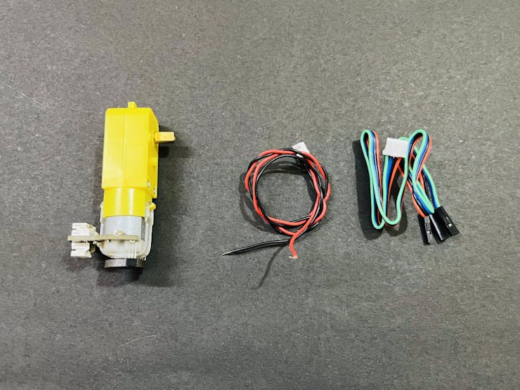
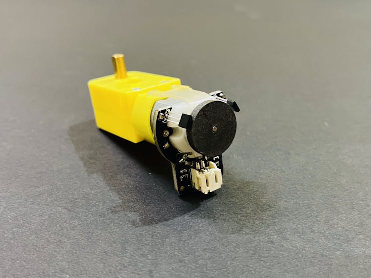
Here I have a BO motor from DF robot, It is a geared motor with 120:1 gear ratio (1 output shaft movement when motor rotates 120 times). It has an integrated quadrature encoder that provides a resolution of 8 pulse single per round giving a maximum output of 960 within one round.
· Gear ratio: 120:1
· No-load speed @ 6V: 160 rpm
· No-load speed @ 3V: 60 rpm
· No-load current @ 6V: 0.17A
· No-load current @ 3V: 0.14A
· Max Stall current: 2.8A
· Max Stall torque: 0.8kgf.cm
· Rated torque: 0.2kgf.cm
· Encoder operating voltage: 4.5 to 7.5V
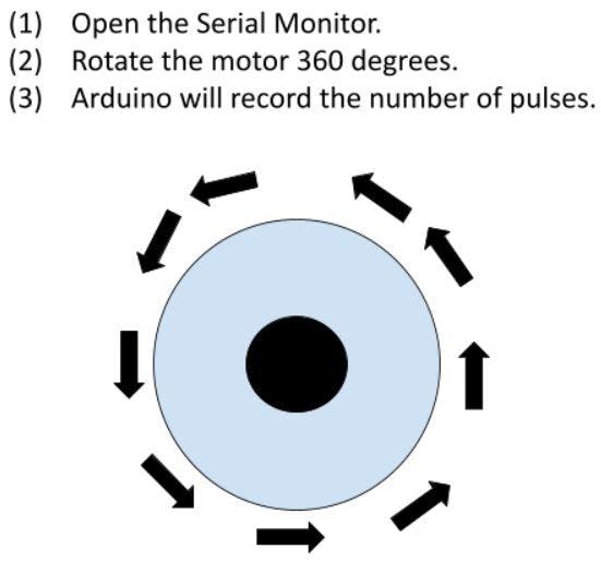
Encoder value calculation: Encoder pulse per revolution = 8 One rotation of output shaft = Encoder pulse per revolution X Gear Ratio So pulse per one rotation = 8 X 120 = 960 Pulse per revolution.
Code for Pulse Calculation:
// Encoder output to Arduino Interrupt pin. Tracks the pulse count.
#define encoder0PinA 2

// Keep track of the number of right wheel pulses
volatile long right_wheel_pulse_count = 0;

void setup() {

  // Open the serial port at 9600 bps
  Serial.begin(9600);

  // Set pin states of the encoder
  pinMode(encoder0PinA , INPUT_PULLUP);

  // Every time the pin goes high, this is a pulse
  attachInterrupt(digitalPinToInterrupt(encoder0PinA), right_wheel_pulse, RISING);
  // 2Nd method to use Interuppt pin (Either use PIN 0 or use funtion digitalPinToInterrupt
}

void loop() {

    Serial.print(" Pulses: ");
    Serial.println(right_wheel_pulse_count);
}

// Increment the number of pulses by 1
void right_wheel_pulse() {
  right_wheel_pulse_count++;
}
Code for Velocity of motor:
This code reset the encoder counter after every rotation which gives the precise number of turns done by motor per unit time.
//The sample code for driving one way motor encoder
#include <Wire.h>
#include <Adafruit_GFX.h>
#include <Adafruit_SSD1306.h>
#define OLED_RESET 1
Adafruit_SSD1306 display(128, 64, &Wire, OLED_RESET);
const byte encoder0pinA = 2; //A pin -> the interrupt pin 0
const byte encoder0pinB = 3; //B pin -> the digital pin 3
byte encoder0PinALast; //Store the previous state of pin
int duration; //the number of the pulses
boolean Direction;//the rotation direction
void setup()
{
Serial.begin(9600);//Initialize the serial port
EncoderInit(); //Initialize function for encoder
Wire.begin();
display.begin(SSD1306_SWITCHCAPVCC, 0x3C);
display.clearDisplay();
}
void loop()
{
Serial.print("Pulse:");
Serial.println(duration);
display.clearDisplay();
display.setTextSize(2);
display.setTextColor(WHITE);
display.setCursor(0,0);
display.print("Pulse:");
display.display();
display.setTextSize(2);
display.setTextColor(WHITE);
display.setCursor(50,30);
display.print(duration/2);
display.display();
duration=0;
delay(300);
}
void EncoderInit()
{
Direction = true; //default -> Forward
pinMode(encoder0pinB,INPUT);
attachInterrupt(0, wheelSpeed, CHANGE); // digitalPinToInterrupt(interruptPin) instead of 0
// syntax of interrupt will be = interrupt pin, function to be executed, Condition of Function HIGH, LOW, CHANGE, RISING AND FALLING
}
void wheelSpeed()
{
int Nstate = digitalRead(encoder0pinA);
if((encoder0PinALast == LOW) && Nstate==HIGH)
{
int val = digitalRead(encoder0pinB);
if(val == LOW && Direction)
{
Direction = false; //Reverse
}
else if(val == HIGH && !Direction)
{
Direction = true; //Forward
}
}
encoder0PinALast = Nstate;
if(!Direction) duration++;
else duration--;
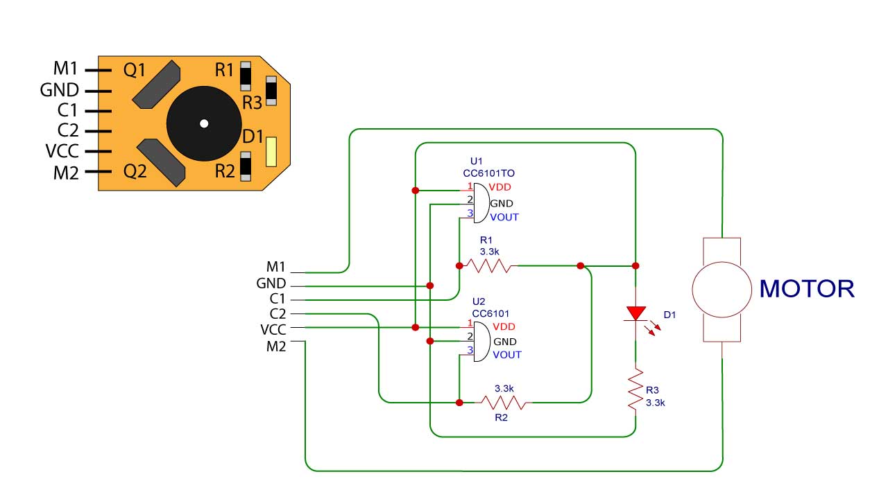
}Circuit:

I found this compatible circuit for the encoder design which itself defines the practical approach. You can see two hall effect sensor for measuring the change in magnetic field according to the movement. The output is sensor is connected to the interrupt pin of the microcontroller. Resistors are used to match the transistor levels and to protect from overcurrent. Download all the codes and schematics from here.
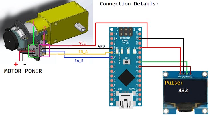
Motor and encoder both can be supplied from same source but keep the maximum voltage readings in mind. Motor can be used without encoder also, just plug the motor wires into power supply and it work as normal one.
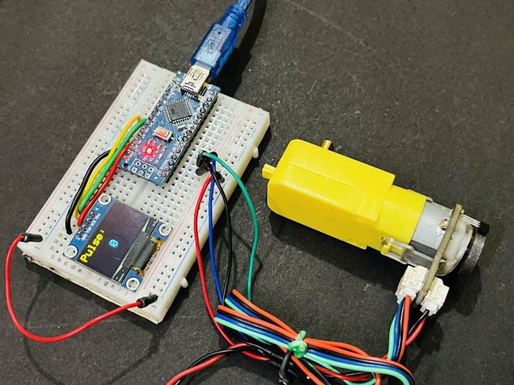
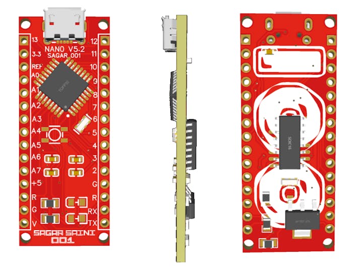
My Arduino:
Here is my own designed Arduino Board, I recently updated one more version. It is fully compatible DIY board. You may use my Gerber files from here to order same board or Upload your own designs directly to JLCPCB and get 5 PCS of 2-layer PCB in just $2.
JLCPCB is the China based PCB manufacturer deals in PCB, PCBA, Stencil, 3D-printing, SMT assembly and Metal CNC. You can assemble the PCB using simple soldering machine by placing all the components or may order Assembled PCB with all components from JLCPCB. Most of the components are available online if you are going to assemble on your own, please check the BOM file given in the download folder.
Testing:
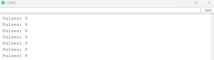
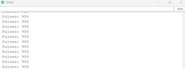
I upload the velocity code and get the number of pulses as a function of speed of motor. The code is written in a manner it will auto reset the encoder value after every 0.3 second. Now keep one thing in mind that operating voltage decide the speed of motor and finally the pulses. I operated my Dc motor on 5volts and got the results displayed in image.
Further from this encoder readings a PID controller or a motor controller can be paired. Which can be used to control the precise movement of motor. This will also solve a problem in robot cars, if we fixed the value of encoder pulses to a range both the motors rotate with same speed providing better control to robotics projects and cars.
Schematics
Reference Schematics of encoder
Velocity code
//The sample code for driving one way motor encoder
#include <Wire.h>
#include <Adafruit_GFX.h>
#include <Adafruit_SSD1306.h>

#define OLED_RESET 1
Adafruit_SSD1306 display(128, 64, &Wire, OLED_RESET);
const byte encoder0pinA = 2; //A pin -> the interrupt pin 0
const byte encoder0pinB = 3; //B pin -> the digital pin 3
byte encoder0PinALast;       //Store the previous state of pin

int duration;     //the number of the pulses
boolean Direction;//the rotation direction


void setup()
{
  Serial.begin(9600);//Initialize the serial port
  EncoderInit();     //Initialize function for encoder
  Wire.begin();
  display.begin(SSD1306_SWITCHCAPVCC, 0x3C);
  display.clearDisplay();
}

void loop()
{
  Serial.print("Pulse:");
  Serial.println(duration);

  display.clearDisplay();
  display.setTextSize(2);
  display.setTextColor(WHITE);
  display.setCursor(0,0);
  display.print("Pulse:");
  display.display();

  display.setTextSize(2);
  display.setTextColor(WHITE);
  display.setCursor(50,30);
  display.print(duration/2);
  display.display();
  duration=0;
  delay(300);

}

void EncoderInit()
{
  Direction = true;   //default -> Forward
  pinMode(encoder0pinB,INPUT);
  attachInterrupt(0, wheelSpeed, CHANGE); // digitalPinToInterrupt(interruptPin) instead of 0
// syntax of interrupt will be = interrupt pin, function to be executed, Condition of Function HIGH, LOW, CHNAGE, RISING AND FALLING
}

void wheelSpeed()
{
  int Nstate = digitalRead(encoder0pinA);
  if((encoder0PinALast == LOW) && Nstate==HIGH)
  {
    int val = digitalRead(encoder0pinB);
    if(val == LOW && Direction)
    {
      Direction = false; //Reverse
    }
    else if(val == HIGH && !Direction)
    {
      Direction = true;  //Forward
    }
  }
  encoder0PinALast = Nstate;

  if(!Direction)  duration++;
  else  duration--;
}
The article was first published in hackster, July 15, 2023
cr: https://www.hackster.io/sainisagar7294/bo-motor-with-encoder-gives-precise-movement-03aaf6
author:sagar saini


